I think that is the value for hovering flight is best. That way the controller doesn’t need to carry a lot of bias.
Well as long as your Rate P gain is tuned properly, you shouldn’t notice much of a difference at all. What you have as VFF is pretty small
As long as you have a clean rate signal, you should set FLTE and FLTD to zero. Setting FLTT higher is a recommended because having it that low will affect the pilot inputs causing some lag between when you make the input and when the flight controller makes the input into the aircraft. So I would definitely set that to at least 20.
Oh. Well that explains why it is so noisy. The leaky part of the controller is washing out the Integrator as soon as some builds. So it is working but not as good as it could if you had non zero ILMI
Hello, So this morning I remake new flight starting from scratch params following your tuning guide.
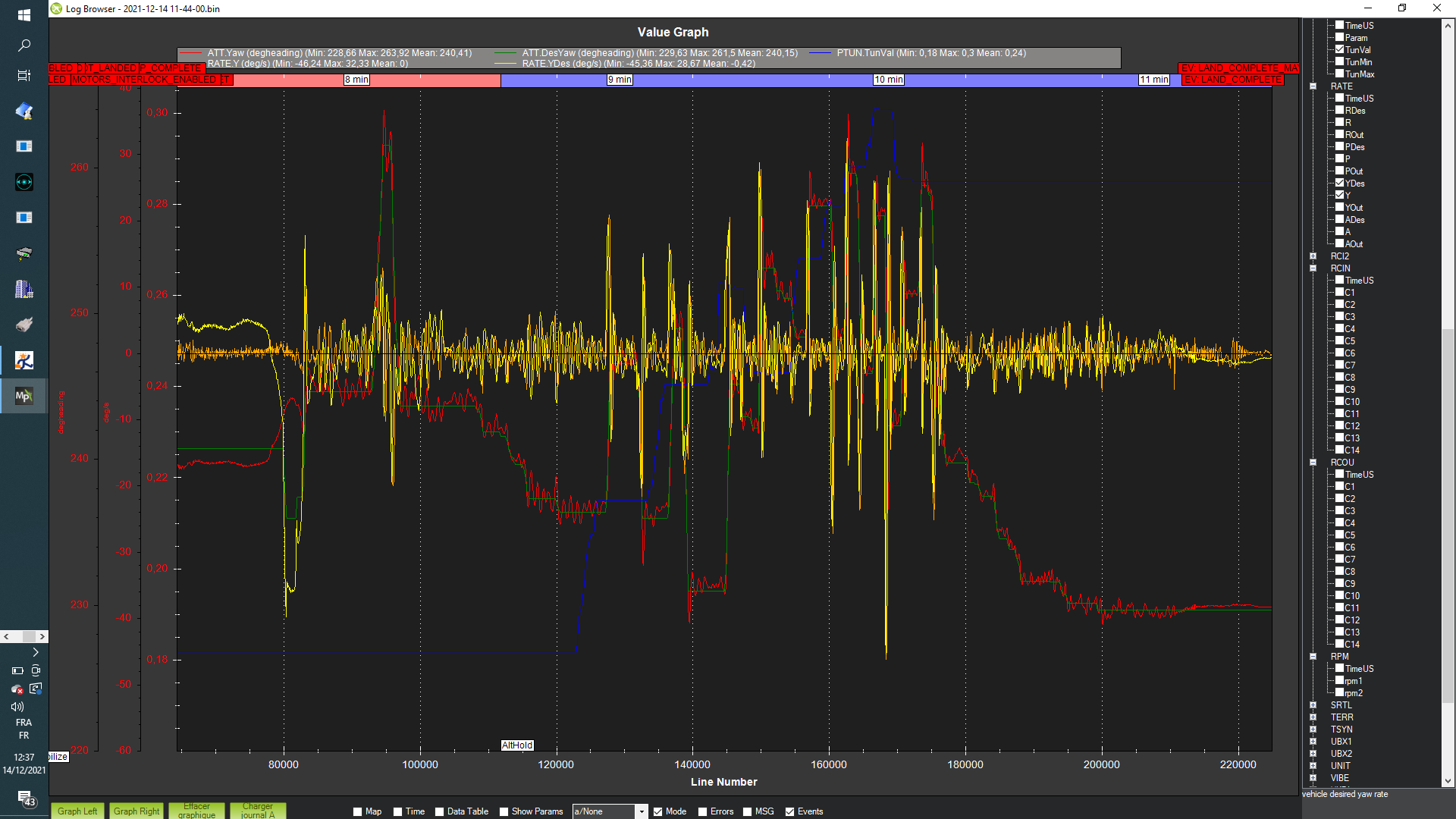
I try to setup YAW. So I follow exactly params listed on the tuning guide.
I can make better than this:
even I tune p from 0.1 to 0.3, you can see sawteeth of 2 deg along the measured yaw…
regarding Yaw target is clear, but regarding Yaw rate controler desired and measured, we can see tht is the rate controller that make this undulations that the machihne follow.
How to make the rate controler make non sawteethed signal???
thank you so much for your help.
Do you think that this can be due to atc_accel_y_max set to 27000??? (maybe to low for this machine?)
@kuspower Sorry that I haven’t had a chance to look at your logs.
Yes I think the ATC_ACCEL_Y_MAX could play a big part in the response you see. The default, as I have learned through my work with autotune, is very low for helicopters. This default was inherited from multicopters. I think you could raise this considerably. Probably over 60000. The only concern when doing this is that the Rate P and Rate D tuning that you have done could be too much and you wouldn’t know it because of the accel max being so low. So incrementally raise the accel parameter and just be aware that you may see it oscillate as you raise it. if so, then reduce your P or D gain until it goes away. However I think your gains are pretty low already.
I was pretty surprised in using the autotune code to see how high I could raise my P gain for yaw on my 600 size heli. What I interpreted as oscillations when I manually tuned the yaw axis were not a sign of instability but just poor tuning. Before I used autotune, I had stopped my yaw P gain tuning at 0.22. With the autotune code, it raised the gain to 0.44 with no sign of instability. It was a huge improvement on the aircraft yaw control. As far as the max yaw acceleration, it predicted my max achievable yaw acceleration to be over 100000.
I only mention this as I think raising the max accel should not cause instability problems and will definitely help with your yaw control response.
I will try to look at your data tonight. I am in the midst of cleaning up the autotune code to prepare it for merging by the new year. So I have been pretty occupied with that.
I tune the rate rll pit pids, and you have the logs off what I do. I think is not perfect, but now is flyable.
After on this log I test LOITER…
And Is kite scary!, it over respond… I supose is due, to quick response of this heli, litler angle give many accel respect to litlle one.
So now I need to tune PSC controler, but I don’t know how to do it.
I like the other controlers? I put PSC Vel or pos PI to zero, and I tune D? after P and after I?
Thank you so much for your help.
Maybe you can give me procedure for it.
You are perfectly wright about action of accel max values.
Tuning roll pitch i see that with roll pushing D and P rapidly gives value that shake but with Pitch even pushing D and P gain quite 20x value of Roll dont give any shaking by security I olded value of x10. I think that 50000 on pitch is also too low……
@kuspower So I see that you have PID message on in the Log but you should also select FAST ATTITUDE in the LOG_BITMASK parameter. This will collect the data at 400 hz which will allow me to see the true frequency of some of the oscillations as well as allow better calculations of accelerations.
I would suggest that you raise this to at least 100000. Then make some sharp stick inputs and then measure the acceleration. You can then set the ATC_ACCEL_Y_MAX to a value slightly below what the aircraft is capable of producing.
I am not following your question here. It appears that the noise in your signals is low so you could set FLTE to zero and just increase FLTT to 20 or 50 hz.
I still think you need to make ILMI non zero. Maybe 0.06. Something to help the controller hold attitude for you
Not quite sure I understand your concern. As far as tuning the position controller, I have not played with that too much. Unfortunately I can’t help you too much there.
Overall, trying to tune your yaw would be a lot easier for me if we used the autotune code. it can perform maneuvers and provide data that gives me better insight on what this issue might be. Some times it is difficult for me to just look at data and determine the problem. yours is a little unique because it doesn’t appear to be a rate controller instability. I’m not sure why there are these low frequency oscillations. Anyway, I may not respond over the holiday as I am pretty busy but I will look at things when I am able.
It seems there is to error on the way who work heli model algorithm that the frame mus follow:
For me ins_offset params are not used.
Even we set it correctly respecting cg of the frame, when frame roll or pitch ekf measure acc on x and y while if ins offset params where used. For me it must not see accs on the body frame but only at accelerometer sensor level as ekf must calculate the leveler arm affects…
Also atc input tc param seems to delay not only target phasing in manual mode filtering rc inputs but it seems to enter in the rate ff and rate pids delaying target achievements. So for rate contrôler there is no error while measuring significant error amount.
Regarding ins ofs params this make impossible to make loiter or automodes work correctly.
As for old position finaly psc controler transform finally error to angles, if in the body frame roll or pitch induce accs even if we dont have quasi accs on the body frame x y, psc cannot work correctly.
In this way trying setting air frame that is bigger than 900 class make it impossible!
Question is : can you show us actual complete diagram that show inputs, filters pids, ff, psc ekf off eache controler for I understand control law of the actual algorithms.
You will need to use the angular rate measurements given by RATE.R for roll rate, RATE.P for pitch rate, and RATE.Y for yaw rate. Plot these signals in mission planner and then determine the slope (change in angular rate/ change in time) to determine the acceleration. you probably need to raise the acceleration max parameters and make sharp stick inputs to get the acceleration data and then calculate the max acceleration. You will convert this acceleration to centidegrees and then set the max accelerations with the value in centidegrees. It would probably be good to set the parameter to 90% of the max acceleration the heli is capable in order to give it some margin.
I have not used this feature as most of the time my flight controller is nearly centered on the center of gravity.
Yes, the input_tc parameter is a command model parameter so it is used to set the desired rates and angles. This parameter is the time constant for attitude response. It is the time to achieve 63% steady state angle for stabilize mode (which affects pretty much all other modes except acro). Not sure I understand your concern here. In addition to the shaping of the target response, you’ll probably notice significant time delay (approx 60 to 100 milliseconds). some of this is due the rotor response but there is also time delay caused by some of the filtering.
Sorry, I am not following what you are saying here.
There is a Control law diagram for the rate/attitude controller but I don’t know of any for the position controller. The rate/attitude controller can be found here. A description of the position controller can be found here which shows a basic control law for the position controller.
No, you can’t set this to zero. It is important that you set this parameter such it matches the capability of your aircraft. A 900 aircraft probably can’t achieve steady state attitude as quick as default value of 0.15 would require. The PSC parameters are set for a vehicle that can achieve attitude response with a Input_TC of 0.15. If your aircraft is slower to respond then you will likely need to reduce the PSC parameter gains.
One last question:
On config tuning menu / extend tuning there is box called basic filters.
Gyro and acc are set to 20hz.
Does the output of this filter feed rate pid controllers?
If its the case even if we set rate flte and fltd filter to 40hz, input is at 20hz?
So you can confirm in this case we must to ever set basic filter to atleast the greatest value set on rate flte and fltd filter?
Yes those basic filters feed the Rate controller feedback paths. You can see it in the control law diagram for the rate controller PID. It is a second order low pass filter. Yes, true that is why I recommend setting the FLTE and FLTD to 0. Why filter the signal anymore and cause more time delay. As long as you adequately filter the rotor noise using the harmonic notch then the PID filters aren’t necessary.
Keep the input tc small. Maybe even make it 0.1 seconds. You would make a step input in angle like an immediate step from 0 deg to 10 deg. Then you would measure the time it took to go from 0 deg to 10 deg. Take that time and divide it by 3 and that would be the actual time constant that the aircraft can achieve. Dividing the time by 3 is based on the assumption of a first order (exponential) response. 3 time constants will result in the response achieving 95% steady state.
Thank you Bill, very thank you, I will remake all the setup from sctrach with all theses details you give me, Im sur that this will help me to tune correctly my heli
Hello Bill, just I’m prepairing tomorrow flight to determine atc_input_tc with attitude fast logging.
I’m thinking that using method you explain we will not measure the same results on Roll/pitch/Yaw…as each axle has it’s intrinsec real rate accel capability. Roll axis is faster than pitch axis…
So in this case what is the good value? the lowest one? the highest one?, the mean value beetween lowest and highest time response measured belong the 3 axis?
what do you think from measuring it from steady hover to sharp input in the different axles, mesuring the time beetween start of tendence on desired angle plot to the start of tendence on measured angle plot ?
like this we can maybe expect to see same time to flex curve on all axis?