Attitude Controller Command Model

I have had a concern for some time about the attitude controller command model. I have had considerable difficulty in tuning heli’s to follow the target (desired) attitudes and rates. There are two parts to this concern. The first is that the attitude controller does not allow for any delay in the system, whether it be for controller computations or actuator. In some of my system identification efforts on helicopters, I’ve determined the delay in the helicopters to be around 40 milliseconds. If you look at the desired versus actual rate traces, I’ve seen 100 to 140 milliseconds. The second is the command model doesn’t represent physically the response of a helicopter. It takes time for the helicopter rotor head to develop the roll/pitch/yaw moment. It appears that the current command model assumes that the moment/acceleration is developed instantly. It is my belief that this makes tuning aircraft more difficult. The rate controller is at a disadvantage because it is trying to make the aircraft achieve an unrealistic target response. Aircraft with a quick response can be pretty easily tuned but those with a lagged response are more difficult to tune, requiring that the command model be slowed down considerably. I think slower responding aircraft could be tuned, providing a better response, if these concerns are addressed.

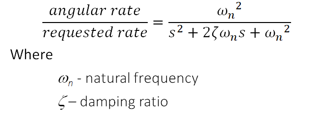
I have devised a new command model that provides a more realistic target response. It is based on a transfer function with a zeroth order numerator and 2nd order denominator, a second order lag. The response is defined with a damping ratio and natural frequency. The damping ratio is set to 0.95 to provide an nice approach to the steady state request with no overshoot. The time to steady state is defined by the user with the frequency. Time to steady state is 1/freq where the frequency is given in hz.

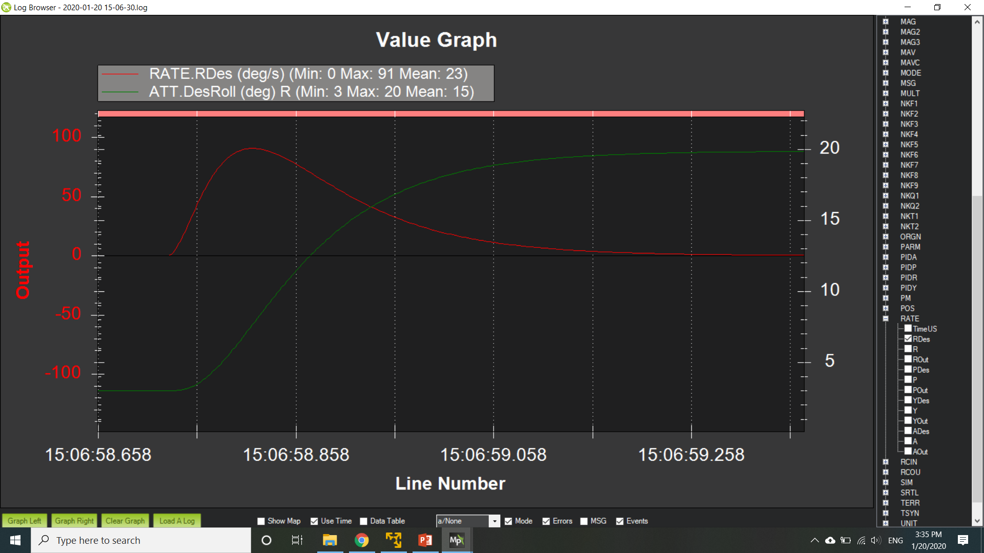
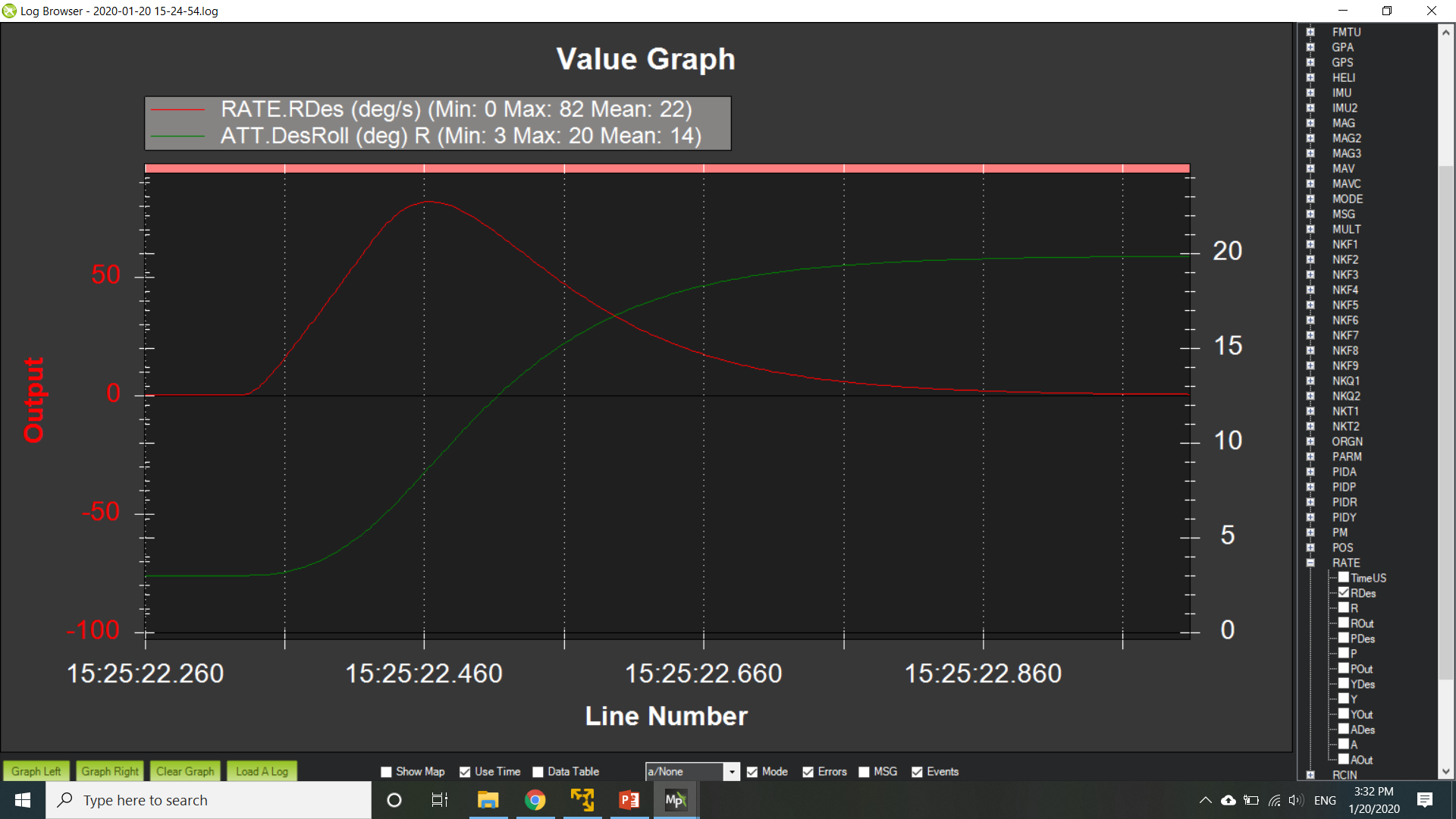
Here is a comparison of the attitude response between the current model and 2nd order lag transfer function. It is important to note that I have modified the output of the rate logging to log the feedforward rate that results from the pilot request. The input_tc for the current command model was 0.5 and the natural frequency for the 2nd order lag was 0.67 hz. The input is a step input to 20 deg requested roll angle. The current command model is shown on bottom with the 2nd order lag model shown on top. You can see the desired rate (red line) on both models start very sharply but the 2nd order lag model is rounded at the peak where the current command model has a sharp reversal. The start of the attitude response is rounded on the 2nd order lag where the current command model is very sharp. Both do a good job with a smooth approach to the target attitude

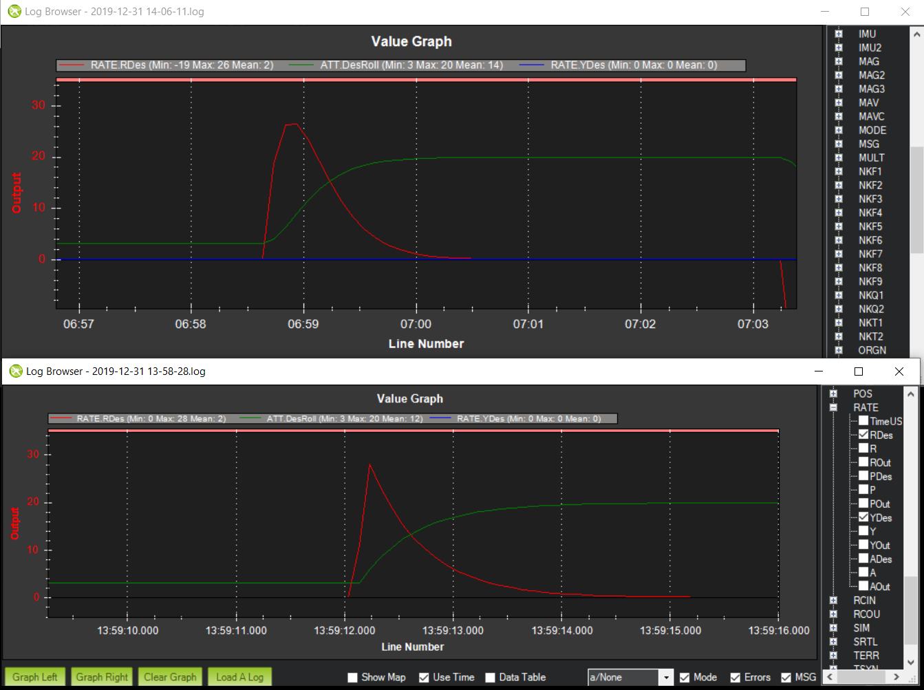
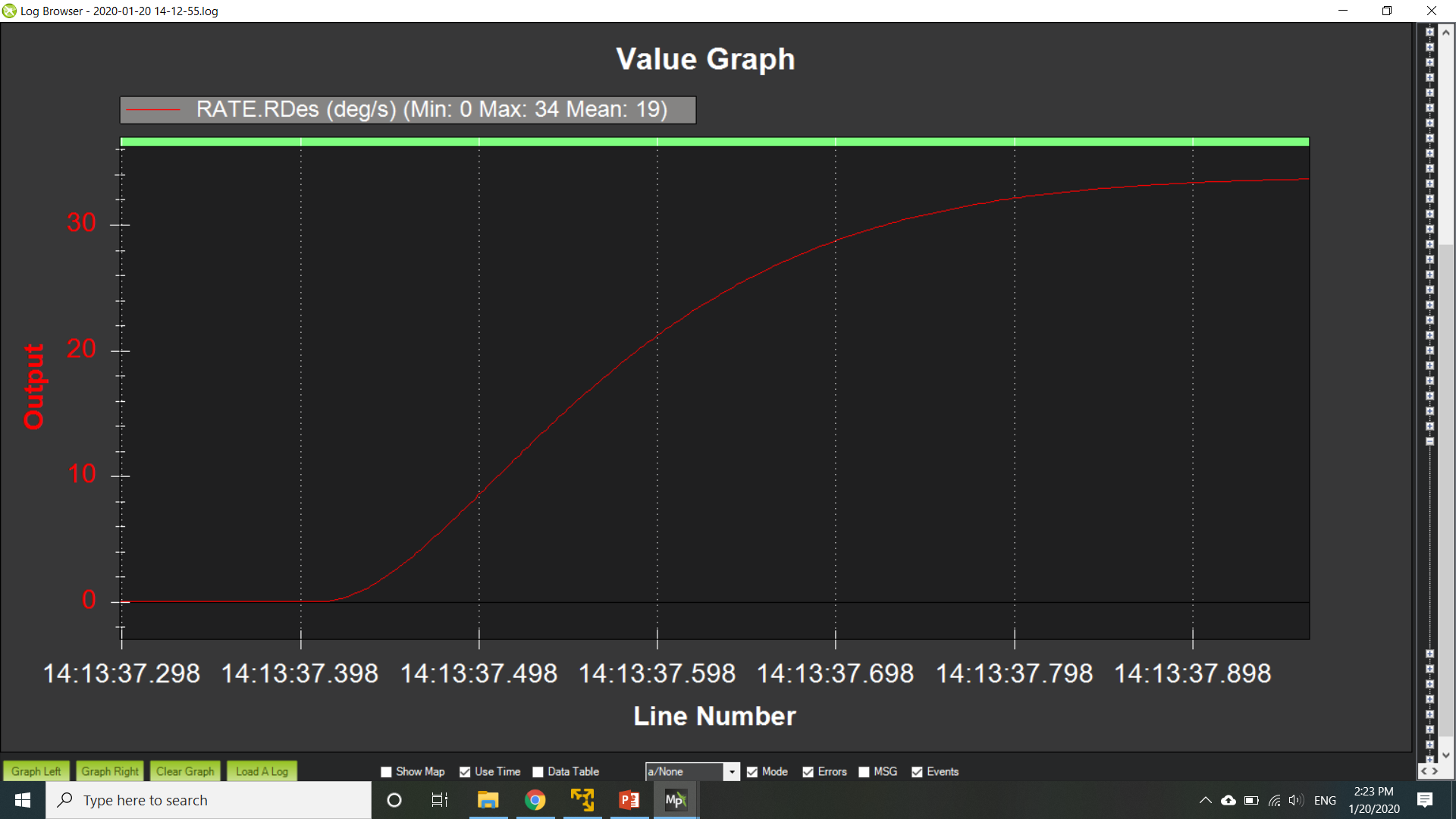
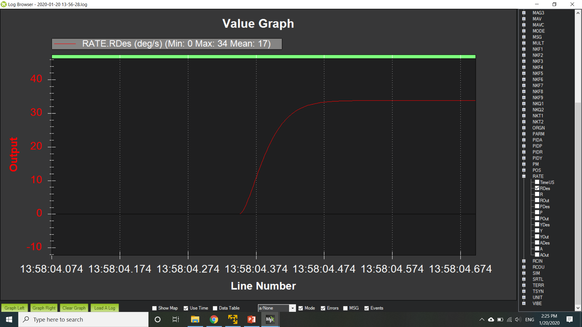
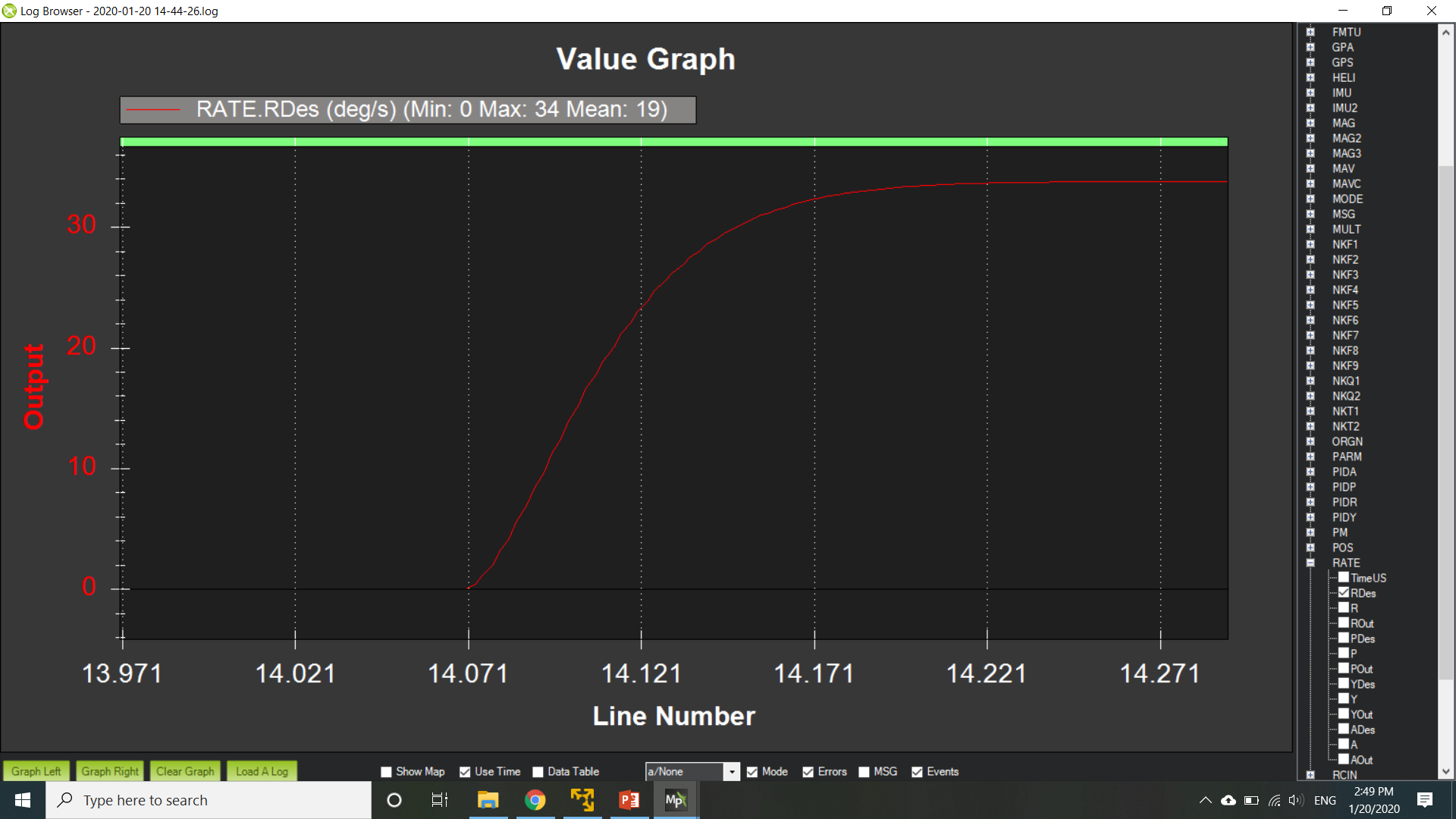
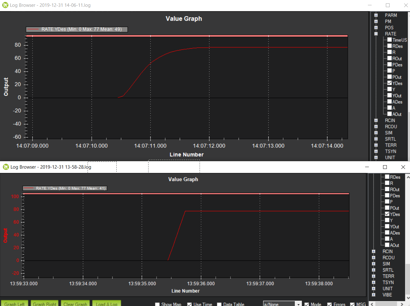
Next is the rate command model. This is a yaw rate command. The current command model yaw is shown on bottom and is basically a ramp in rate to 80 deg/s with a constant acceleration of 250 deg/s/s. This doesn’t model the actual response very well and makes it difficult for the actual aircraft to keep up. I used the same 2nd order lag model to accelerate the aircraft to the desired yaw rate which is shown in the top plot. The frequency was the same as the attitude response. So it could be increased for the rate response. Probably 2 hz, which produces a time to steady state rate of 0.5 seconds, would be a better choice. Again with the second order lag model, the aircraft response is better modeled and gives the aircraft a fighting chance to keep up.

I have the proposed command models and the time delay in the feedback path coded up. I hope to go and test this on an actual heli in the coming weeks.

1 Like

When I did the original quaternion controller I recognised this issue and that is where the input time constant went some way to smoothing the departure and approach acceleration. However this does not appear to be present in the graphs above and I wonder what that time constant was set to.

The rate input does not make use of this time constant so it still has these sharp edges.

The work I have been doing on the S-Curve stuff has got me thinking about the attitude controller input shaping again but the requirement to constantly update the set point from any state combined with the complexity of the equations makes me wonder if it is computationally practical. At very least it is another brain twister of a job that will not be practical for me to tackle until the rewrite of the Navigation controller has been completed, optimised and made flexible enough to cover the various requirements of the vehicles that will use it.

Given the background above I fully support looking into this problem. I believe the ideal response is a jerk limited response similar to what would be produced by an s-curve. When looking at the curves above I think we should be looking for a response that curves up in rate, then curve over to a maximum rate (like the first figure) then curve down and smoothly back to zero. The first two figures both do not show the initial curve into an increase in rate.

Ideally the rate response would be symmetrical about the peek with the initial curve into rate increase and curve as the rate becomes zero again being symmetrical about a curved peek. The main issue with our current implementation is the lack of jerk limiting as the rate increases initially. At the moment it is only acceleration limited. However this example does not appear to address this issue. However, I would have thought a second order low pass filter response would have given an initial curvature so I am a little confused and would need to look into what you have done further.

So I am glad you are thinking in this direction! I think we are still missing the initial jerk limited, or finite jerk, initial rate increase to achieve your initial desired outcome.

Thanks and i am sure we will be talking about this soon :slight_smile:

1 Like

The input time constant was set to 0.5 sec. Obviously much longer than usual. Since writing this I found out that the logging rate was pretty low and is why we see such jagged response. So I redid the comparison for 0.3 time constant and it shows much of the same response for the current controller. However one thing to mention here is that I left the accel max at 110000 cdss. So I think the accel limit helped shape the initial rate response that you may have noticed in your original work. Since this was a longer time constant, the accel limiting never kicked in to help shape the rate response.

So I looked into this more and your right that the second order response when applied to shape the attitude, doesn’t affect jerk directly. So the initial acceleration application is instant. So I worked on that and I think I have an acceptable solution for the attitude shaping. Will post my results in a few hours once I complete my evaluation but it is looking promising.

1 Like

Here is an update to the work that I have been doing to improve the command model. I will start off with a discussion of the rate command model as my discussion of the attitude command model will build upon the rate model.

Rate Command Model
The rate command model is based on the 2nd order transfer function below

image

The damping ratio which dictates how much overshoot that will occur on the capture of the steady state rate was set to 0.9. This was done to allow a little overshoot in order to get to the steady state rate quicker. The natural frequency dictates how quickly the steady state rate is achieved. It works out that the steady state rate is achieved within the period of the natural frequency. So if the natural frequency was 2 hz then the steady state rate is achieved in 0.5 seconds (1/freq). Time constants are used when referring to first order systems and steady state rate is nearly achieved in 3 * time constant. So to keep the parameters consistent, I determined the frequency from the time constant.

I developed a new function for the rate command model which was used in place of the function “input_shaping_ang_vel”. This function uses the accel_max parameter to limit acceleration and also limits jerk. Currently there is no parameter to specify the jerk limit and is hard coded to frequency divide by the time step (dt) which through looking at various natural frequencies provides a nice lag to acceleration demand.

This plot show the rate response with no accel limiting with the same jerk limiting based on time constant. The input time constant is 0.20 sec which is equivalent to a 1.7 hz natural freq. This would be maybe a time constant for a larger heavier UAV.

So here is a plot of rate response with no accel limiting with the current jerk limit built into the code. The input time constant is 0.05 sec which is equivalent to 6.7hz natural freq. The jerk limit is computed based on the time constant. This would be a time constant of a smaller more agile quad or helicopter.

The acceleration limiting works nicely to reshape the response. However with this prescribed second order response, it is easy to determine the expected max acceleration which is given by input size times frequency, where frequency is in rad/s. I would argue that accel limiting is not needed because the input time constant should not be set such that the max acceleration is exceeded. But the function handles the accel limiting well as shown below for the input time constant of 0.05 with the max accel set to 1100 deg/s/s where the computed max accel for this time constant is 1400 deg/s/s. It can be seen that the time to steady state almost doubled.

Attitude Command Model

The attitude command model uses the current square root controller smoothing function but runs the rate requests through the rate shaping command model which provides for jerk and accel limiting as shown above.
Below is a plot of the attitude and rate for an attitude request of 20 deg. The input time constant (ATC_INPUT_TC) was set to 0.15 and there was no accel limiting.

This next plot shows the response for the same time constant but with the acceleration limited to 800 deg/s/s. You can see how the rate response flattens out more on the increase in rate.

In both cases, the rate trace shows the jerk limiter providing a nice curvature on the initial acceleration.

If you are interested in looking at the branch, it is here. Some things to think about.

  • should the user be allowed to specify the jerk limit. I’m a little hesitant because using wrong number will have a bad effect on the shaping model for the attitude shaping. The rate shaping model can handle overly limiting accelerations and jerks fairly well.
  • are acceleration limits necessary since the response is prescribed and users can adjust the input time constant to the capabilities of the vehicle. Or maybe we still need them for the applied corrections due to attitude error.