Note: This document is applicable to Cube Orange and Cube Black flight controllers. The IIC interface available that can be used to connect multiple TF-Lunas is the same on both flight controllers. TF-Luna can be used with PixHawk Cube for the purpose of obstacle avoidance and Altitude Hold. But because it’s a short range sensor so in most cases it is used for obstacle avoidance.
TF -Luna Settings :
Note: If there are any spikes while using the LiDAR as obstacle avoidance sensor then it is advised to change the frame rate to 250Hz, see the command details having command ID as 0x03 in the manual and for the sake of convenience configuring other parameters (like setting frame-rate, changing address etc.) in UART mode is recommended if you don’t have IIC-USB converter. A simple UART-USB adapter or board should work.
At the time of writing this document latest firmware was 3.3.0. For firmware upgrade please contact our technical support.
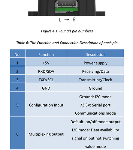
The default communication of TF-Luna is UART. LiDAR comes with a single cable. In order to use IIC the cable needs a little modification, details are mentioned in the coming paragraph. Please see TF-Luna IIC communication pin details as below:
If we look at the pin configuration of TF-Luna, IIC can be set by grounding pin-5 in addition to the other four pins . For this purpose a customized cable is needed because in IIC mode we need to connect both pin-4 and pin-5 to the ground.
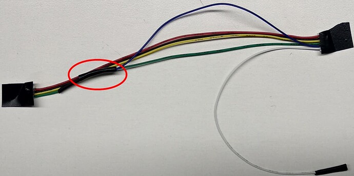
The modified cable is shown below. I have connected green wire (pin-4) and blue wire (pin-5) to single pin which will go to the GND pin of the source. Leave pin-6 connected. Please ignore the color standard in this case as black wire represents RXD/SDA while yellow wires represents TXD/SCL, just follow the pin numbering according to the user-manual.
TF-Luna, TFmini-S, TFmini-Plus and TF02-Pro can be interfaced with IIC port of PixHak Cube Orange flight controller. Their settings are almost same. We take two TF-Luna LiDARs as example and set the addresses 0x08 and 0x09 separately.
PixHawk Cube Connection:
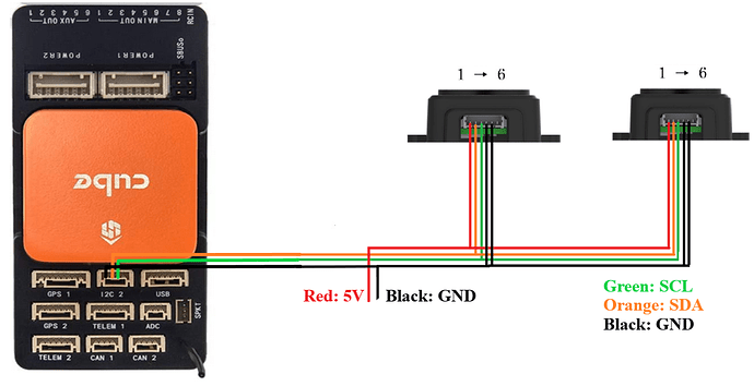
We take PixHawk Cube Orange flight controller as an example:
Figure 1 : Schematic Diagram of Connecting TF- Luna to I 2 C Interface of PixHawk Cube
Note:
Default cable sequence of TF-Luna and PixHawk Cube are different, please change it accordingly (SDA and SCL wires need to be interchanged). Look at the pinout of controller, pin configurations are:
IIC connector should be purchased by user
If TF-Luna faces down, please take care the distance between lens and ground, it should be larger than TF-Luna’s blind zone (20cm)
If more TF-Lunas need to be connected (10 LiDARs are supported), the method is same.
Power source should meet the product manual demands:5V±0.5V, larger than 150mA (peak current)*number of TF-Luna
Parameters settings :
Select [CONFIG/TUNING] and then click on [Full Parameter List] in the left from the below bar. Find and modify the following parameters.
Common settings:
AVOID_ENABLE= 2 [if 3 = UseFence and UseProximitySensor doesn’t work in IIC then choose 2 = UseProximitySensor ]
AVOID_MARGIN=4
PRX_TYPE=4
Settings for first TF-Luna :
RNGFND1_ADDR=08 [Address of #1 TF-Luna in decimal]
RNGFND1_GNDCLEAR=25 [Unit: cm, depending upon mounting height of the module and should be larger LiDAR than non-detection zone]
RNGFND1_MAX_CM=400 [It could be changed according to real demands but should be smaller than
effective measure range of LiDAR, unit is cm]
RNGFND1_MIN_CM=30 [It could be changed according to real demands and should be larger than
LiDAR non-detection zone, unit is cm]
RNGFND1_ORIENT=0 [#1 TF-Luna real orientation]
RNGFND1_TYPE = 25 [TF-Luna IIC same as TFmini-Plus IIC]
Settings for second TF-Luna:
RNGFND2_ADDR=09 [Address of #2 TF-Luna in decimal]
RNGFND2_GNDCLEAR=25
RNGFND2_MAX_CM=400
RNGFND2_MIN_CM=30
RNGFND2_ORIENT= 6 [#2 TF-Luna real orientation]
RNGFND2_TYPE=25 [TF-Luna IIC same as TFmini-Plus IIC]
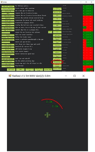
Upon setting of these parameters, click [Write Params] on the right of the software to finish the process. After writing the parameters you need to power off the controller and then turn it on to apply the setting changes. If the error message “Bad LiDAR Health” or “Bad Proximity” appears, please check if the connection is correct and power supply is normal. How to see the target distance from the LiDAR: press Ctrl+F button in keyboard, the following window will pop out:
Click button Proximity , the following window will appear:
The number in green color means the distance from LiDAR in obstacle avoidance mode(the number only refresh when this window opens, closes, zooms in or zooms out, it doesn’t mean the real time distance from LiDAR and will not be influenced in Mission Planner. The mission planner version at the time of writing this tutorial was v1.3.76.


