Hi,
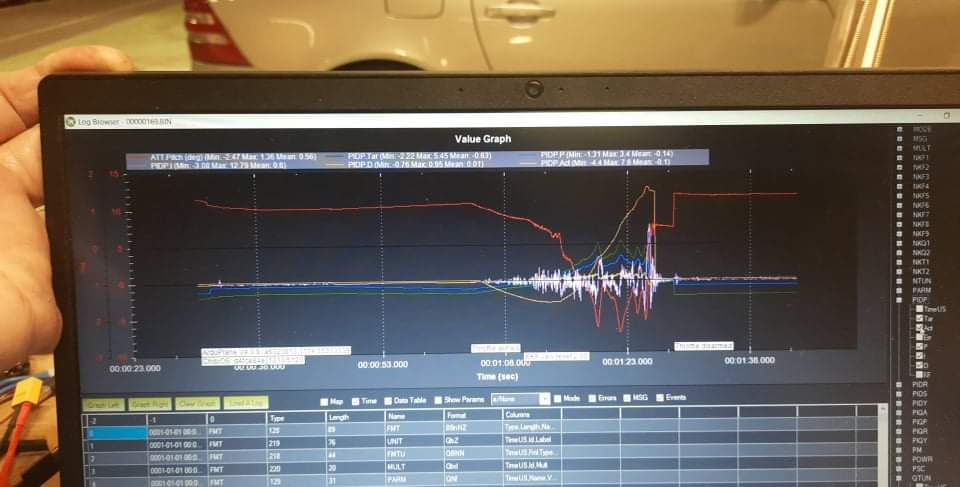
I am trying to tune the PID values on my drone using the data log files in my flight controller (bin file). The log browser brings up many possible parameters to track and many have similar names, making it confusing. Let’s say I want to tune the Pitch PIDs:
What is the name of the Pitch signal being input into the Pitch PID controller (target)?
What is the name of the output Pitch signal being fed back into the PID controller (actual)?
What is the name of the Pitch error signal of the PID controller?
Thanks, William
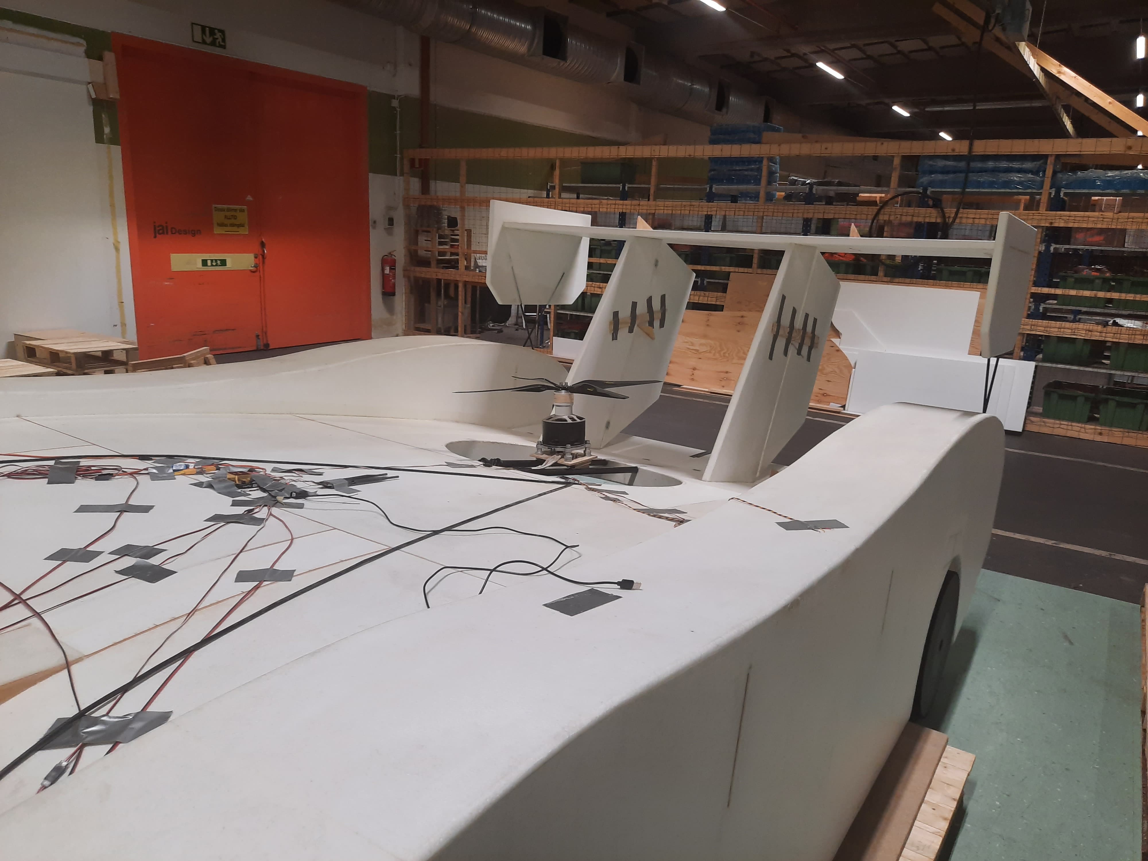
Here is a link to see the drone I am tuning the PIDs on:
Hi,
It would also be nice to track the signals in realtime using the (Tuning) option in the bottom of the DATA screen. Can the above parameters be tracked there and if so what would be their names?
I am developing a drone and want to learn how to tune the PIDs using the data observed the data log. For the test in the data log file, I have the vehicle pivoted at its base, so the back motor can lift the back end of the vehicle and have the flight controller try to stabilize it in pitch at about 5 deg angle.
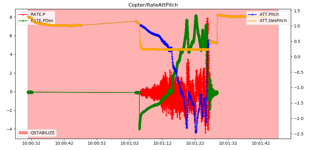
I have selected some signals that I think may be what I am looking for. Please comment on the selected signals, and if they are correct, how do these signal suggest I change my current PID values? Ref attached picture. My current PID values are:
P = 1.0
I = 0.2
D = 0.01
Color code in picture:
Red = actual pitch
Blue = target pitch
Purple = actual pitch
Green = P
Orange= I
Yellow = D
Hi Andrew, Thank you very much for your answers and analysis. I am building inside a metal warehouse , so the GPS and magnetometer do not work very well inside. Right now we are just trying to get the vehicle to hover inside as stable as possible, so we didn’t think we need these working yet. In fact the GPS\Magnetometer is not yet even mounted on the vehicle. But of course when we go out side, these should and will be setup properly.
Regarding the Q_ M parameters. We are using different motors for the front and back. The 2 front tilting motors are 10kW motors and run on a 14S battery each, and the back 18kW cont/40 kW peak motor runs on two 14S batteries in series. So the front and back motors run on different voltages and therefore use different ESC voltage types. So I am not sure how to input the data required for the Q_M parameters.
Regarding the signals you graphed. Can you tell me what these names correspond to in the following PID diagram?:
Att is an attitude measured in degrees. Rate is a rate of change of attitude, measured in degrees/second.
The low level PID controllers are rate controllers, so the PIDx log messages log the performance of that rate control. Performance of the higher level attitude control is in the ATT message.
If didn’t previously enable the log bitmask to log the PIDx parameters, are the ATT and RATE the only parameters that can be used to review the tuning perfomance?