Hi Jim,
Welcome aboard! We posted the English Configuration Lists (2100 and 2300) above already but thanks for the offer. Perhaps you can post some photos of your pre-built Freeman when it arrives.
Cheers!
Hi Jim,
Welcome aboard! We posted the English Configuration Lists (2100 and 2300) above already but thanks for the offer. Perhaps you can post some photos of your pre-built Freeman when it arrives.
Cheers!
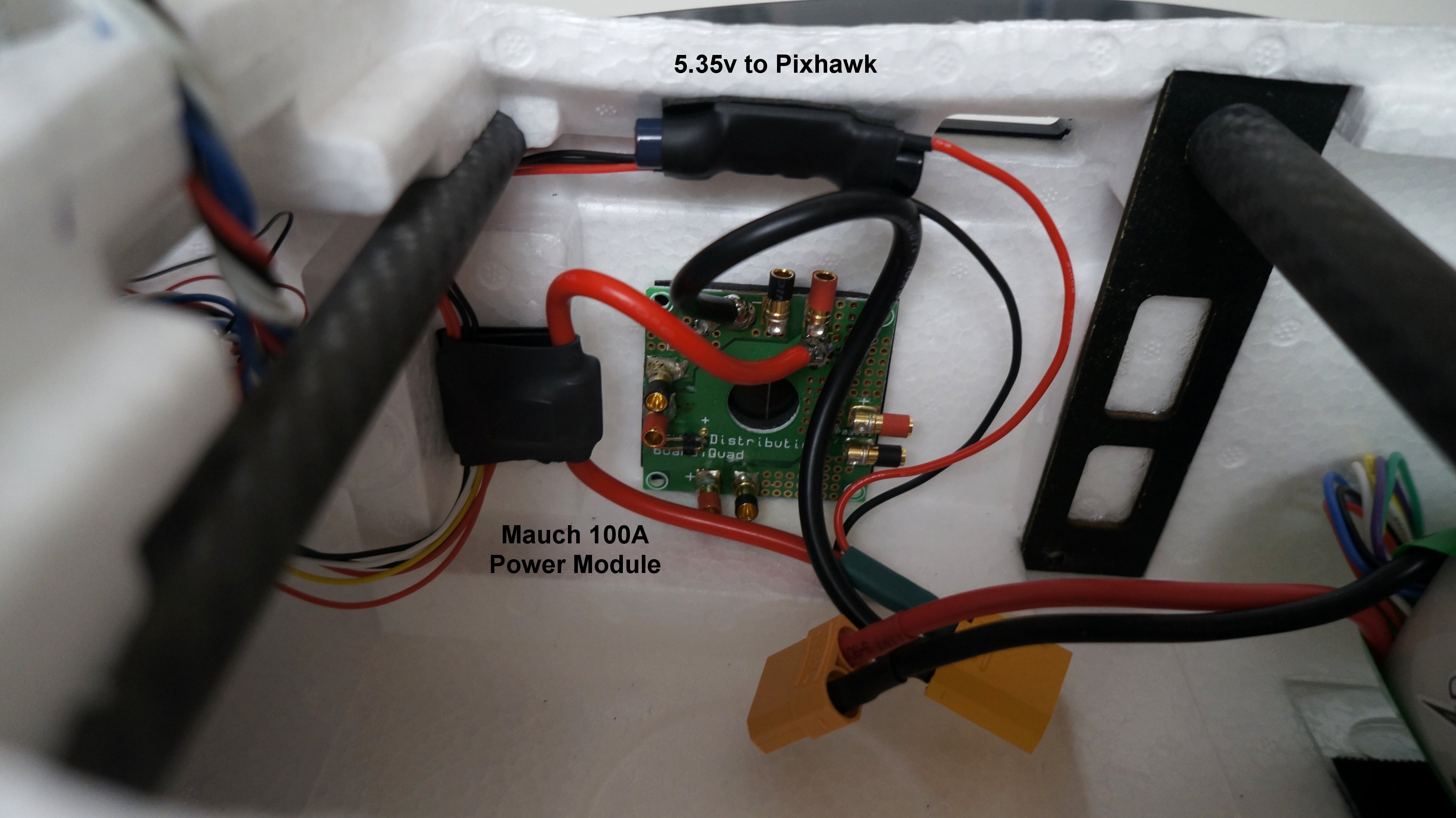
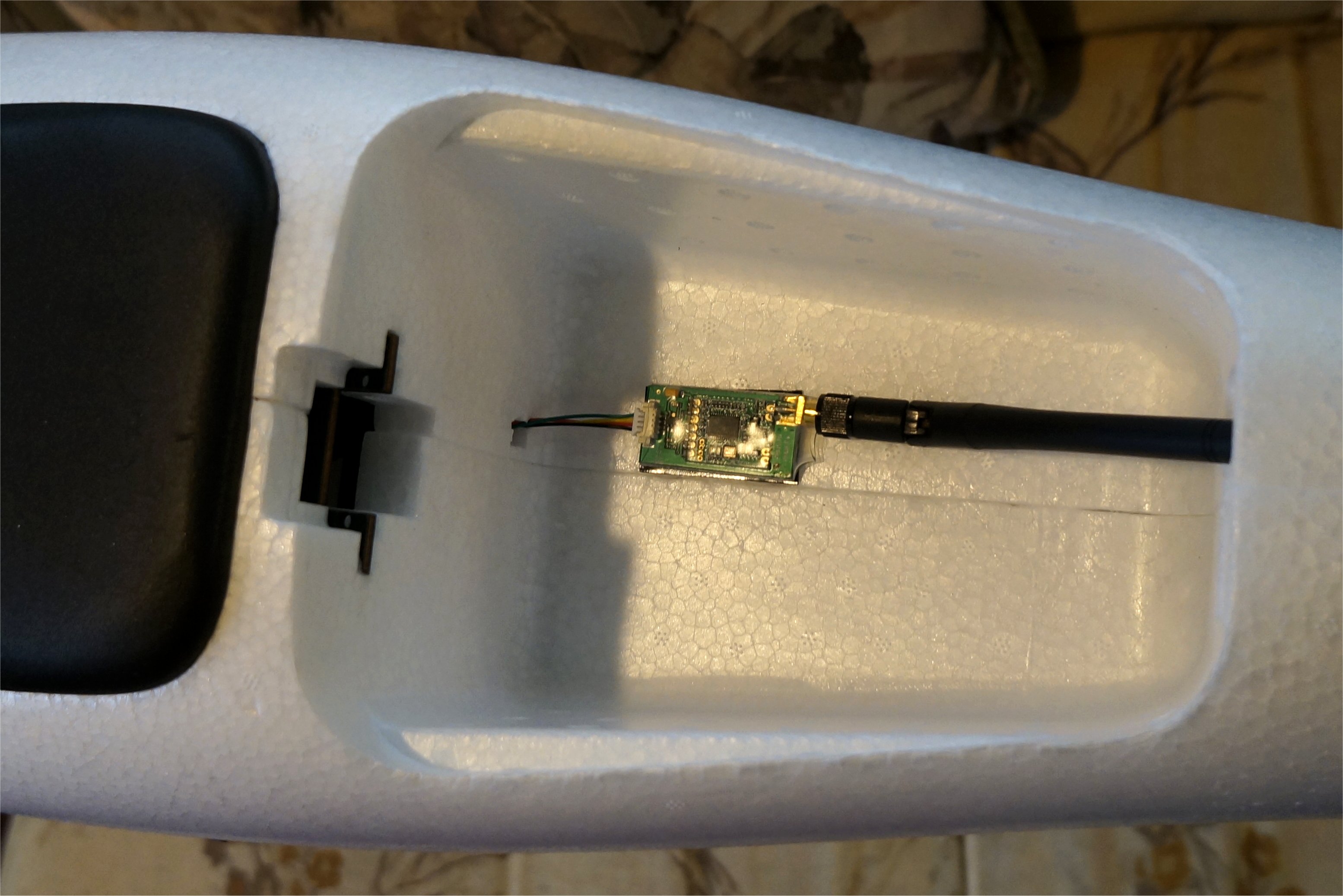
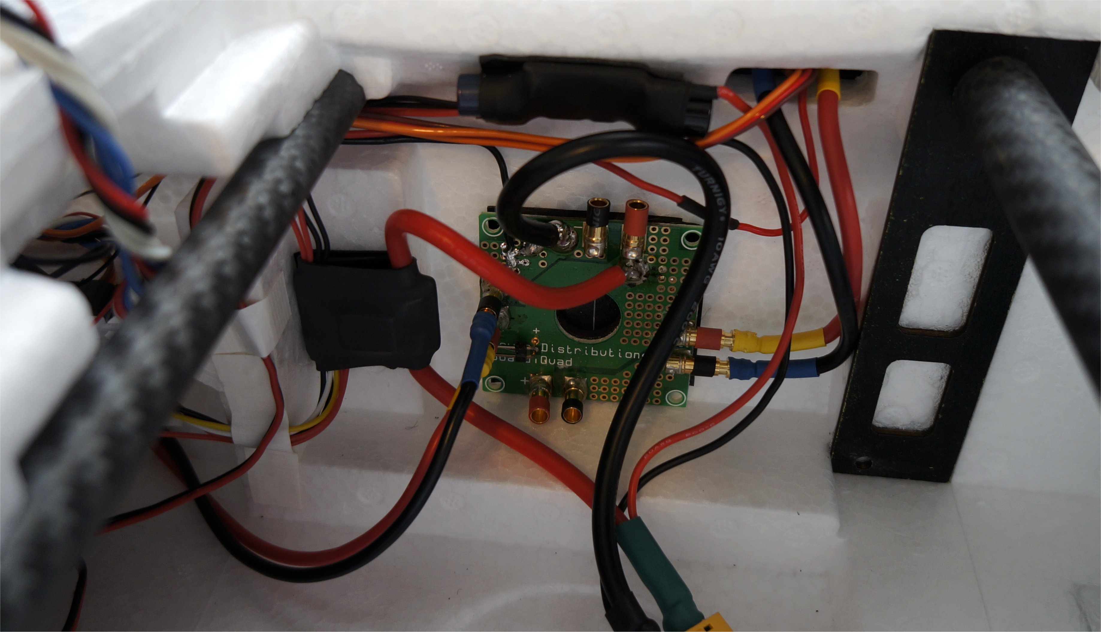
My Mauch 100 amp Power Module arrived so I installed it carefully planning my power distribution, ease of connection to the main battery, connection to the Pixhawk, and keeping the mapping area free for a camera. I did need to extend the 6-wire cable to the Pixhawk and change the connector to a white Molex style but I had plenty of these spare cables on hand.
Using a Hobby King Quadcopter Power Distribution Board worked well on the Nimbus VTOL so I also installed one here to run battery power to the wings and regulators via 3mm bullet connectors. You can re-solder the board bullet connectors to face out to suit your needs. There is also a 2-pin red JST connector on board for lower current needs like the 5v regulator to the Pixhawk servo rail.
David
I found the same thing when I tried Tabao and I also tried other sites as well. So I ended up ordering directly from them using a paypal account to transfer the money to them.
Hopefully, MFE will find an English distributor to sell the Freeman soon.
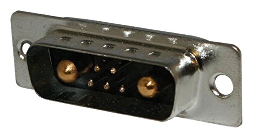
I looked into the Sub-D connector specs and didn’t have much luck. The manufacturer of the supplied connectors, Shenzhen Winen Electronics, only had similar connectors and no specifications on their Web site.
Other manufacturers like NorComp, distributed by Newark, and others, have the following ratings.
Hi Greg, I think it is the same connectors: 7W2 30A https://ru.aliexpress.com/item/32946200433.html?spm=a2g0s.9042311.0.0.1ec633edcXX692
It’s the same type of connector (Sub-D) but a different version. The Winen version that we have has all the pins, power and signal, about the same length on the solder side. I’ll ask Mr. Chang if he can get the specs.
Cheers!
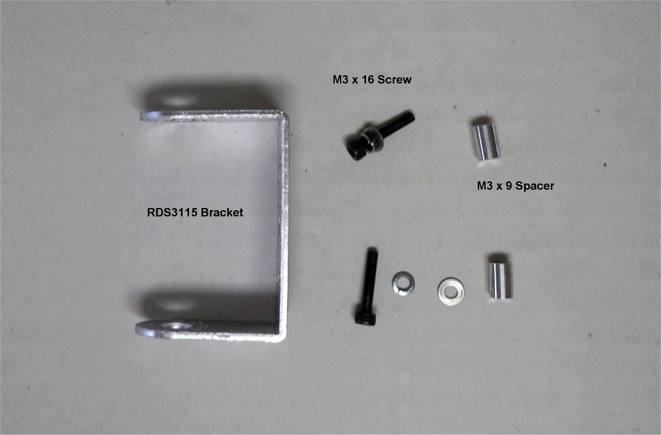
My assortment of M3 Aluminum Standoffs arrived from eBay so I selected the 9mm length which provides an offset close to my Nimbus VTOL setup…which I have had no issues with all summer. An M3 x 16mm screw works nicely when using a washer and lockwasher behind the robot servo bracket. I also add Loctite to the motor mount holes.
You could drill the center hole larger so the axle collar will fit through the bracket but I was afraid to weaken the bracket. Likewise, leaving off the shaft collar which helps secure the motor housing from pulling off was also a concern.
Hi Greg,
I tested a couple of different types of spacers, and threader spacers appeared to work the best in this application. With regards to D-sub connectors, I usually go for trusted brands like Amphenol or NorComp for UAVs that carry expensive payloads. This VTOL tilt-rotor build, however, is only going to be used as a test platform.
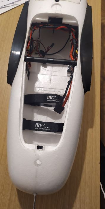
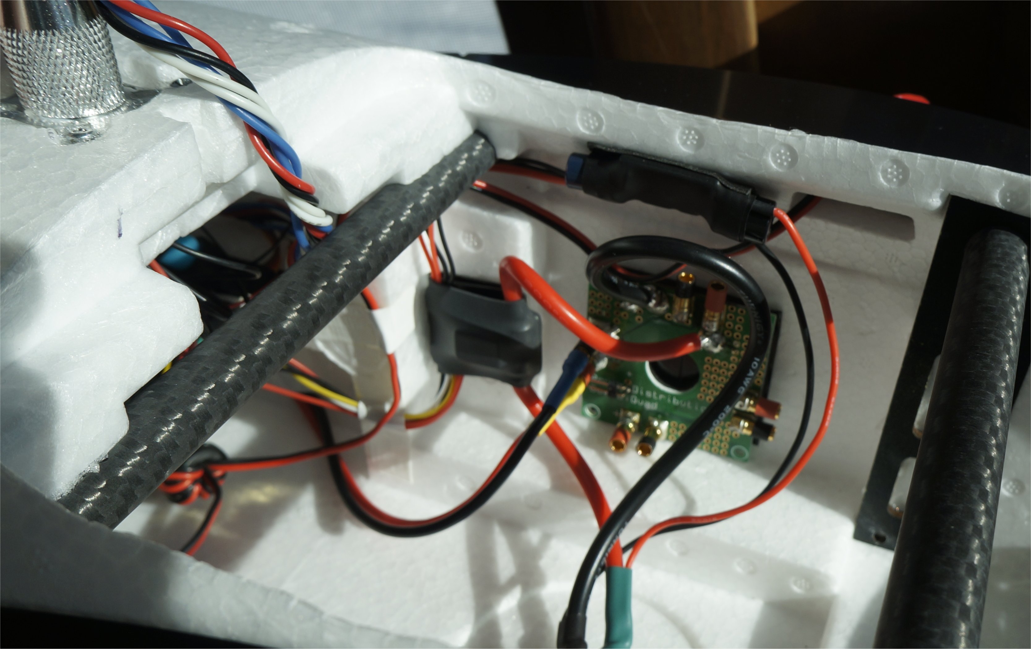
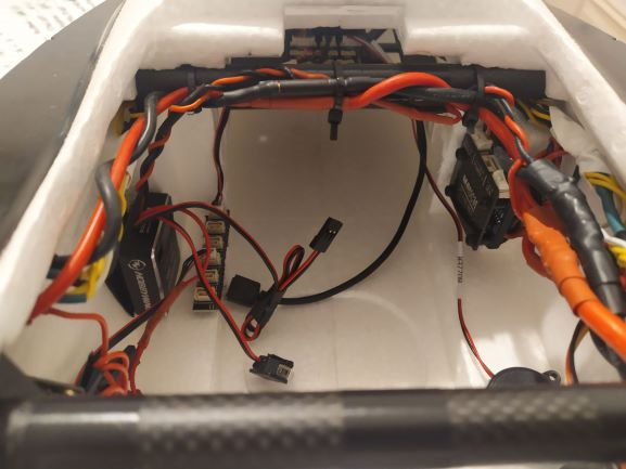
Anyway, I have finished the wiring for this plane a few days ago (I have attached a couple of photos of the fuselage wiring). However, weather isn’t looking favourable here at the moment, so flight tests will have to wait.
Hi Wasim,
Thanks for the photos. The wiring looks pretty similar to how I envisioned it. I see that you are also using a Mauch PM. Although they can be difficult to mount, they are a much better solution than the 3DR-style PM.
On the threaded spacer, I don’t see how you can get it to properly lock down on both the bracket and the motor. The idea of the spacer is that the screw still provides the locking force to the washers.
Where have you set your CofG to? The markings seem covered on these VTOL wings.
Cheers!
My bottom cover for the parachute bay seems odd. I was wondering how others have secured this cover on either a Freeman or Believer.
It’s intended to be secured via a servo, but that’s rather pointless unless you have a parachute. I just tape it.
I usually go for the Mauch PM and BEC for the added sense of reliability.
The spacers I use are threaded all the way through, so I use M3 bolts that pass through a washer and the bracket, then the associated spacer and finally the motor. Although you have to fiddle with it slightly more to tightly secure the bolt through the four layers (i.e. washer, bracket, spacer, motor), once you’ve done it, it feels far more secure because the threads on bolt confines the spacer relative to the bolt better (compared to relying on friction at the ends of the spacer alone).
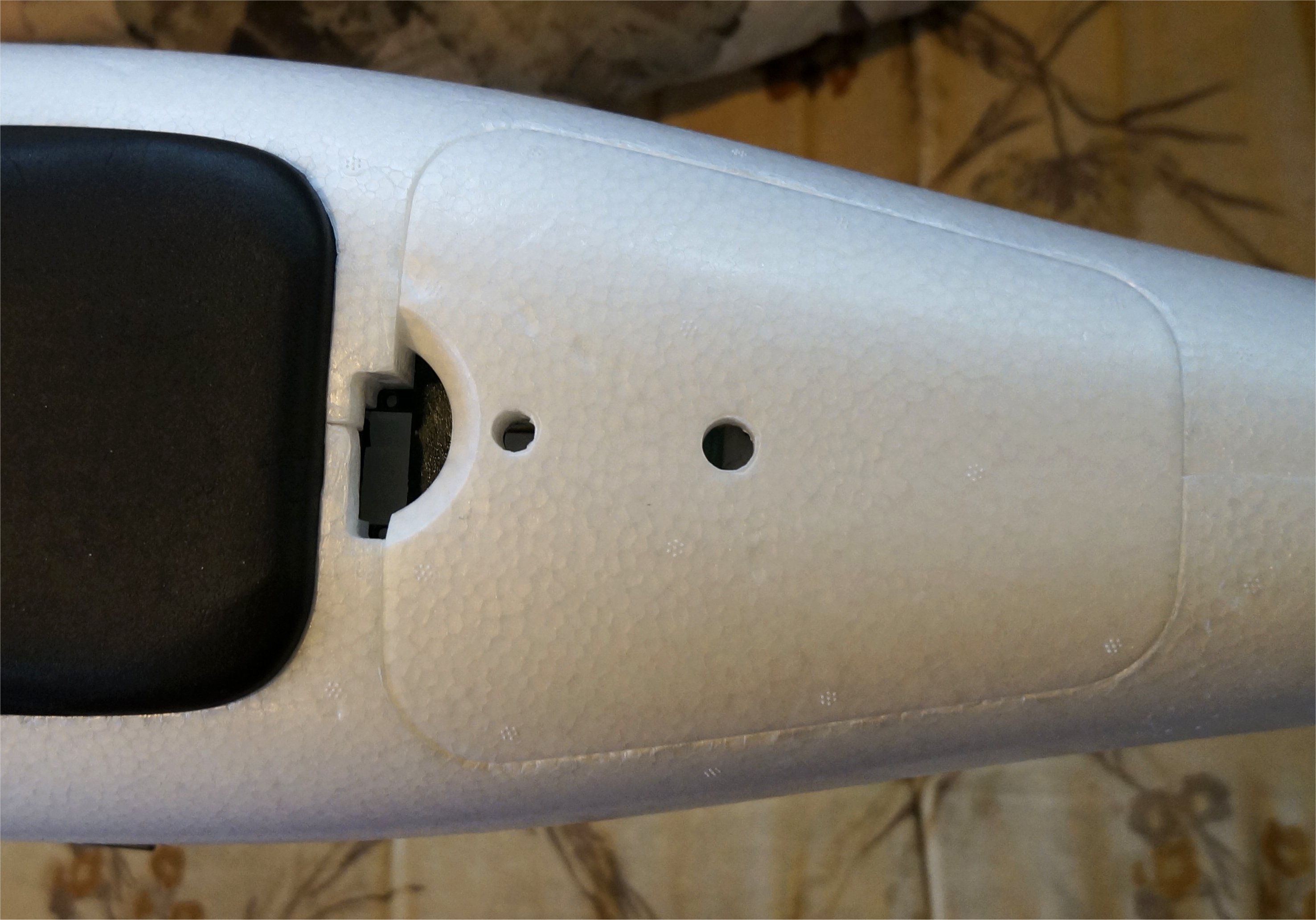
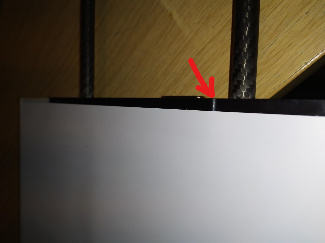
I usually use the rear end of the ridges on the Believer wing adaptors for balancing. These ridges are still noticeable in the wings that came with my VTOL kit (although partially covered) - please see photo attached.
The opening on the fuselage at the parachute compartment just looks odd (or rather misaligned) for everyone I suppose. I have never used a parachute, so I have never used a servo for securing that compartment. Like James, I used tape to secure them in a couple of my builds (and resorted to a permanent seal in one).
Greg did some digging what I came up 5amps on the signal pins max,
Yeah, most of these connectors all seem to have 5 amp rated signal pins. It was the two outer power pins that are in question as they can vary…even with the same manufacturer. I suspect that they must be at least 20-30 amps, which will feed 10-15 amps to each motor in hover modes. The supplied connectors are gold plated so they are nice. No reply yet from Mr. Chang.
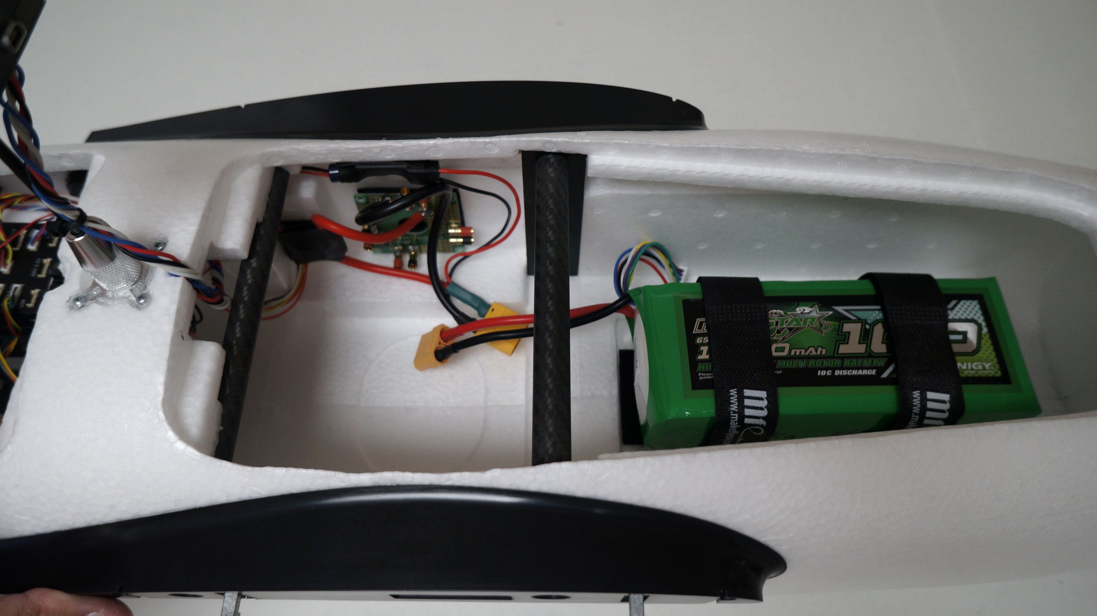
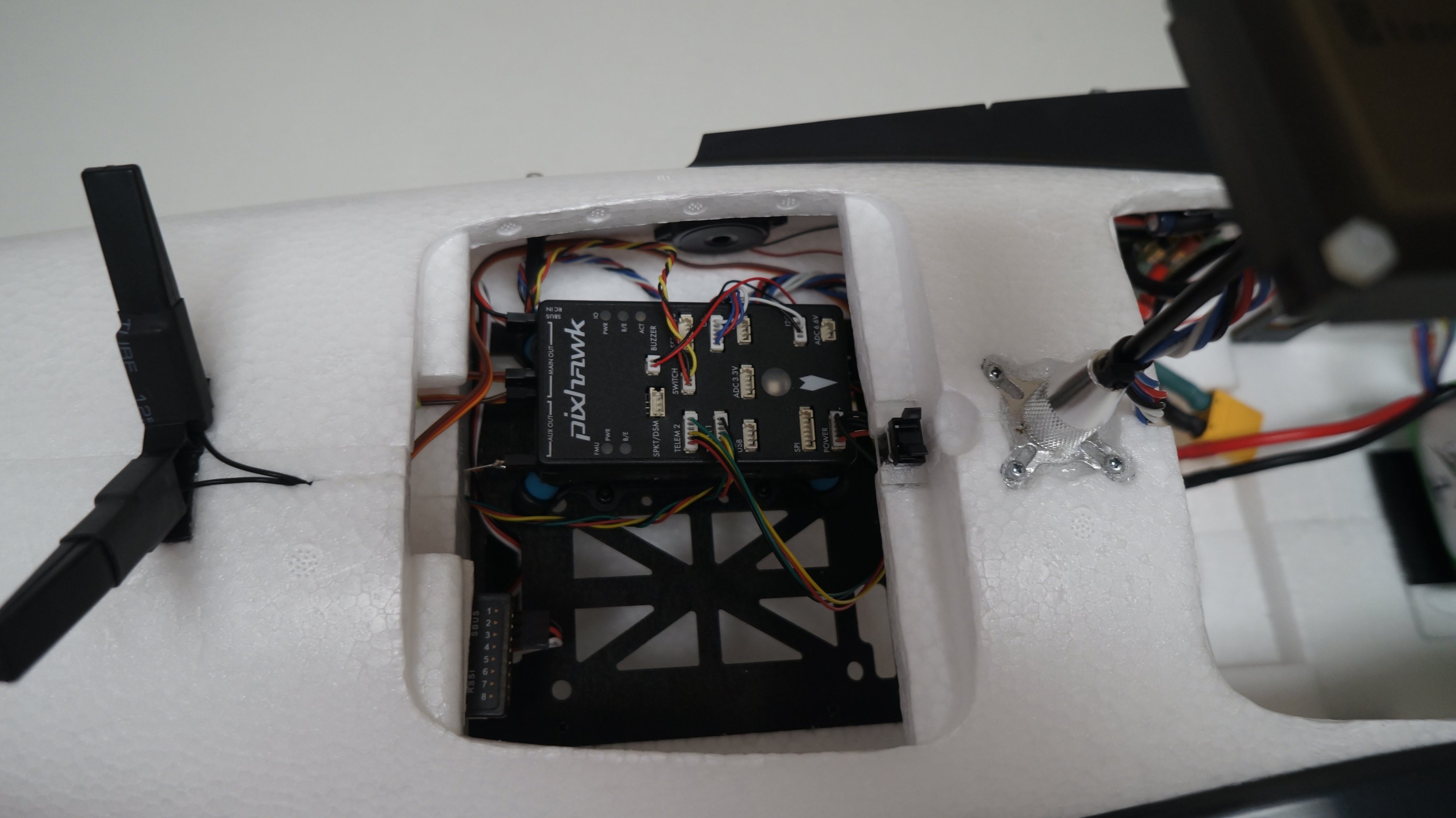
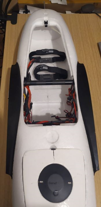
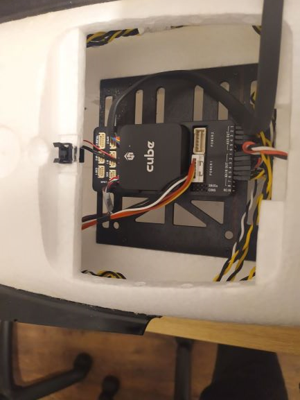
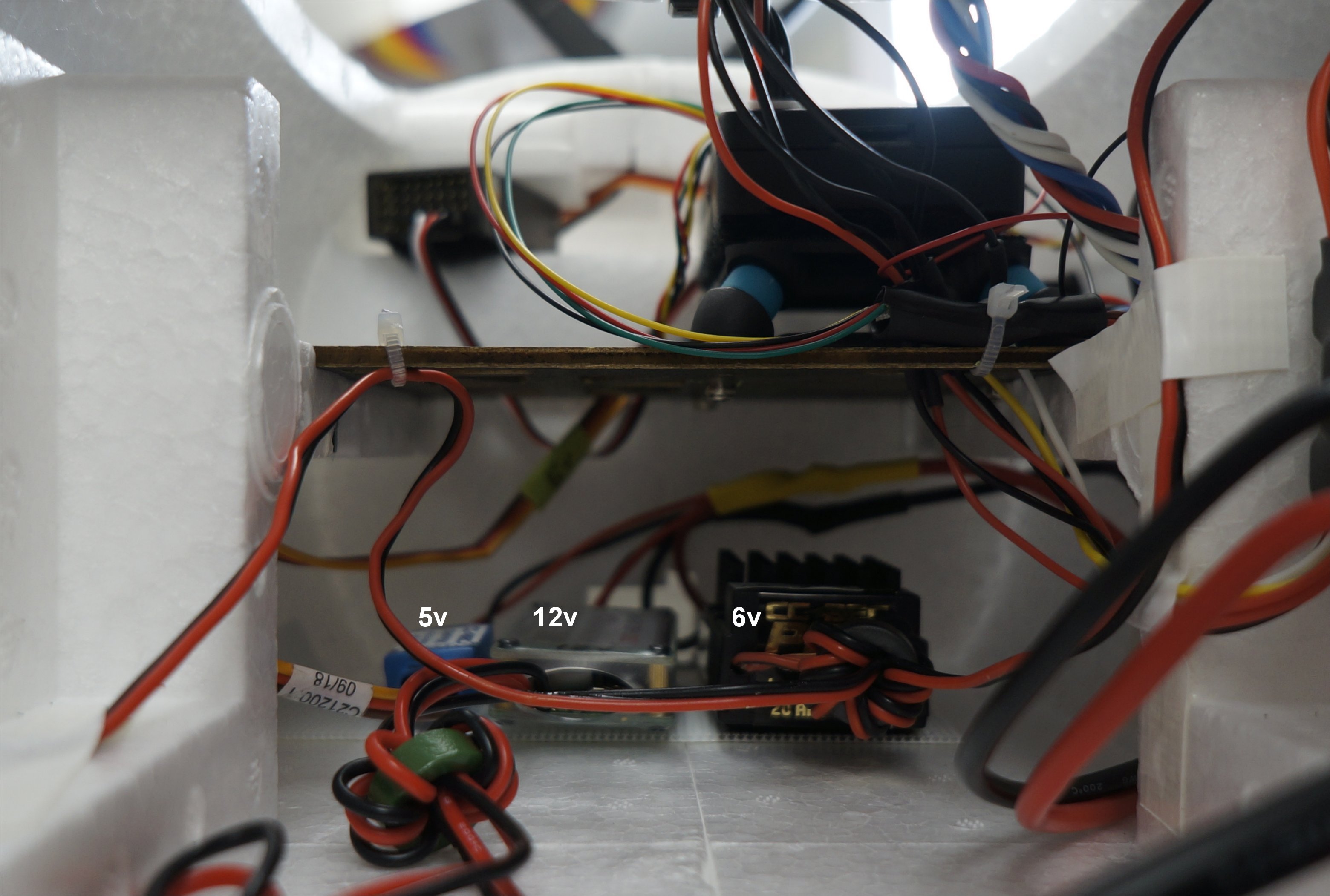
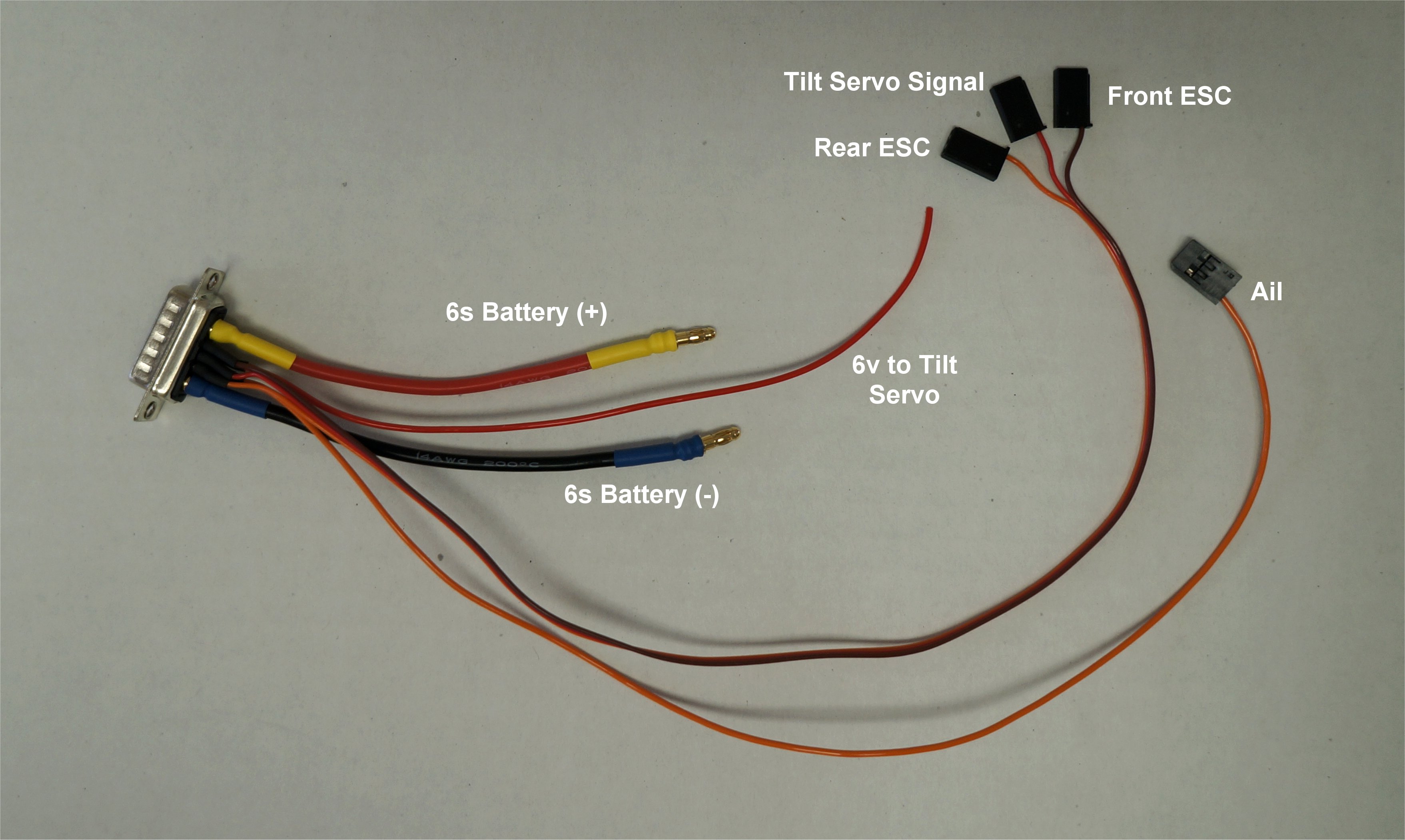
After a break to work on some indoor flyers, I finished my other wing wiring and started on the fuselage. I wired three regulators up to one of the battery power bullet connectors and placed them in the chamber under the Pixhawk.
The CC BEC 5v regulator is plugged into the Pixhawk rail to power the tail servos and ESCs. It also acts as a backup to the Pixhawk if the PM ever fails. This creates warnings on the buzzer and GCS if it ever happens.
The 12v regulator is for my camera gimbals and the 6v CC BEC Pro regulator is for the aileron and tilt servos in the wing. These were all regulators that I had on-hand.
Greg, I powered the servos the same way you did. I power the tail servos using a seperate bec (which powers the servo rail on Pixhawk), unlike what was implied in the wiring diagram provided with the kit.
I soldered the needed wires to the left wing Sub-D connector using the wire supply that came with the kit. If you don’t use 6v on your tilt servo, you can keep the red wire running along the aileron cable and just plug it into the Pixhawk rail for power. Although the Pixhawk can handle 6v on its rail, it eliminates the back-up functionality to the PM.
From the Wiki:
The servo rail can supply servos requiring up to 10.5V (but not also power the Pixhawk). Voltages above 5V cannot be used to power the Pixhawk via the servo rail. In this case the Zener diode must not be used .
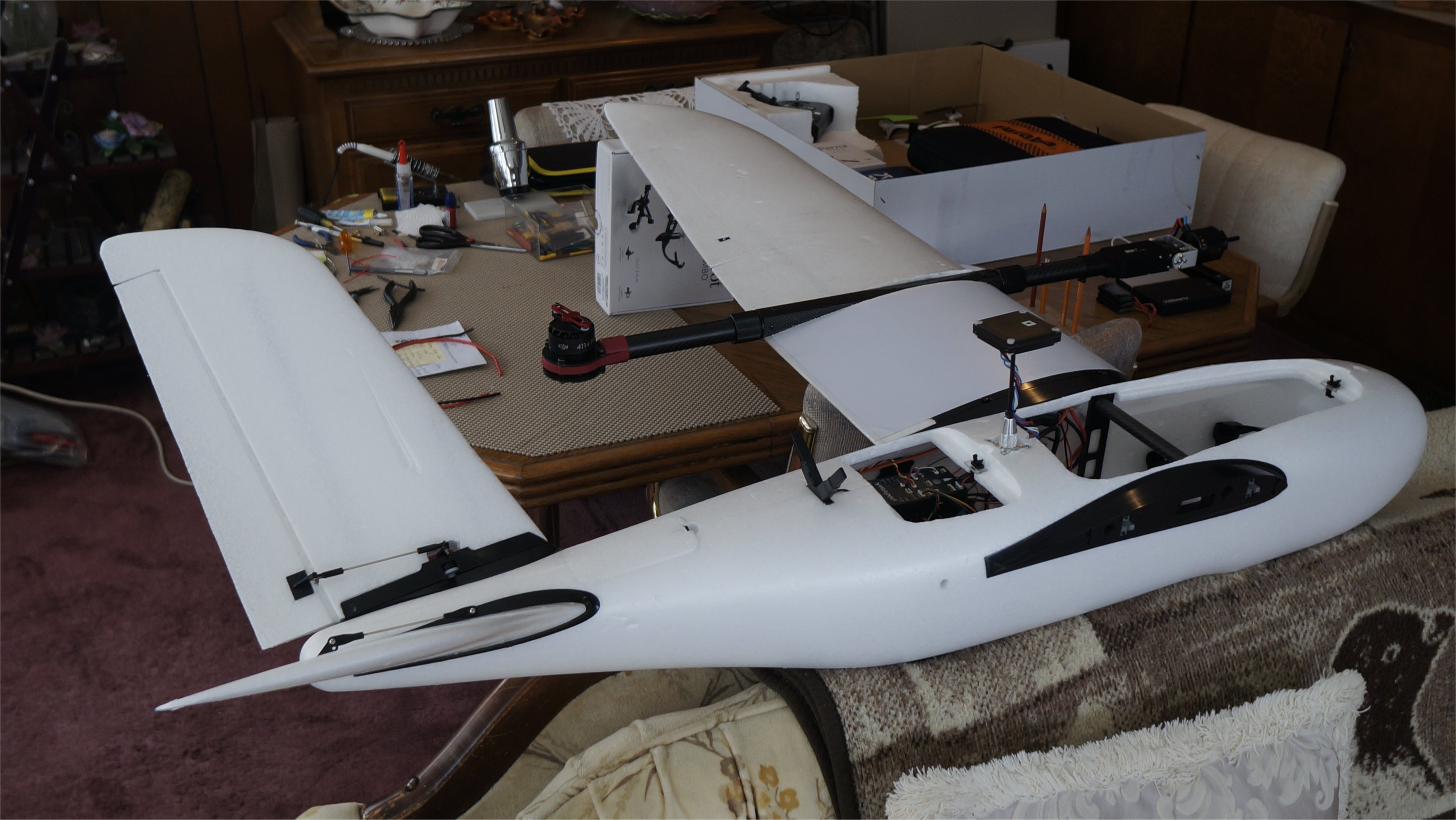
I finished wiring the chassis for the left wing and decided that it was time for a sanity check (a.k.a. blow up test) so I installed the v-tail and left wing. To my joy, it powered up fine and everything worked! I had v-tail control for elevator and rudder. I had aileron control and tilt rotor control. All controls were in the proper direction, including the compensation in FBWA mode. It was a good milestone!
thanks Greg for the update and pics
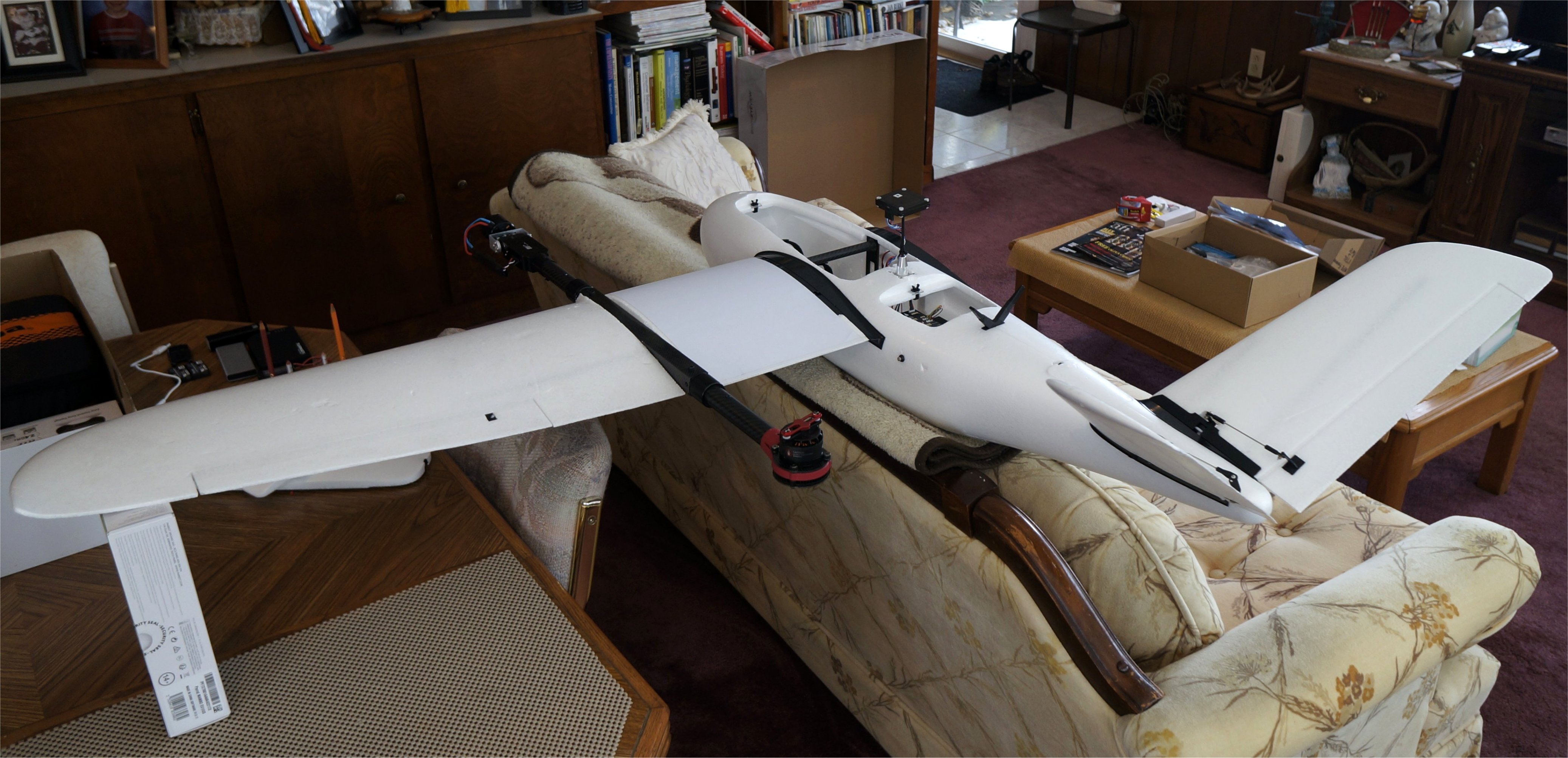
I finished the chassis right wing wiring and was able to test the entire setup using Mission Planner. I could arm the plane and all motors spun in the correct directions. I haven’t done an ESC calibration yet and may wait to see if it is needed. I am not certain if the rear DJI ESCs calibrate like the Xrotor ESCs.
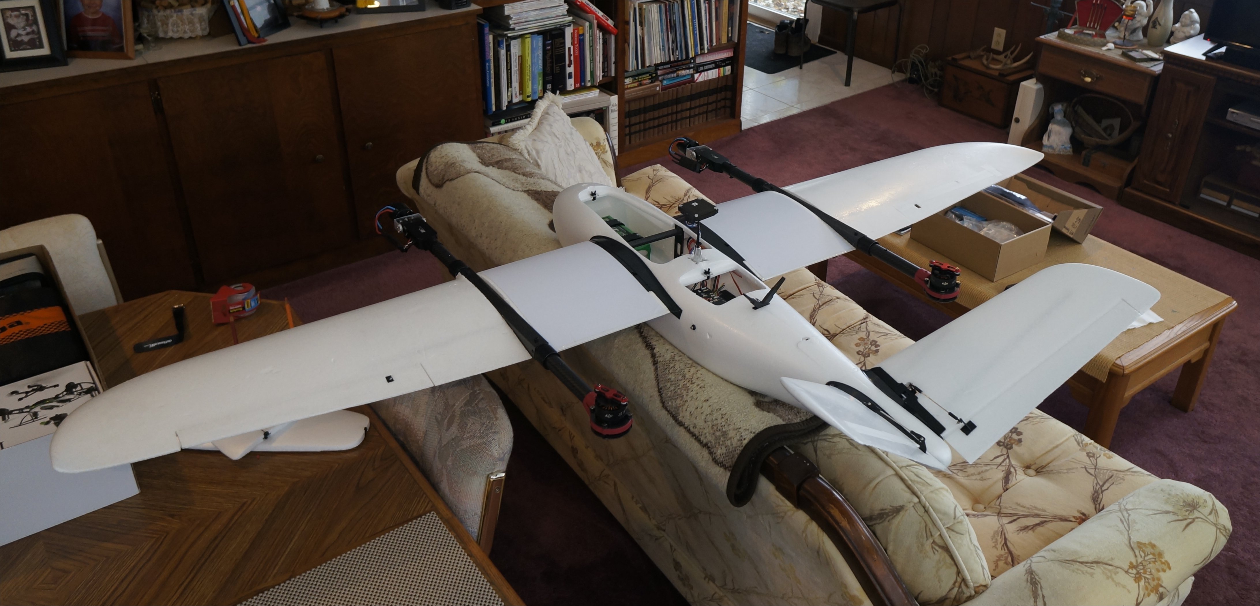
With the 6s 10AH battery in the center position as shown, the plane is quite tail heavy. Moving the battery full forward still required 7oz (198g) of added weight in the nose to balance properly. This is a good sign since it means a larger battery can be used, if desired. In my case, I plan to mount a 3-axis gimbal and GoPro camera up front. The mapping camera will mount in the designated belly area.
Hello!My WeChat ID is 17683271960.