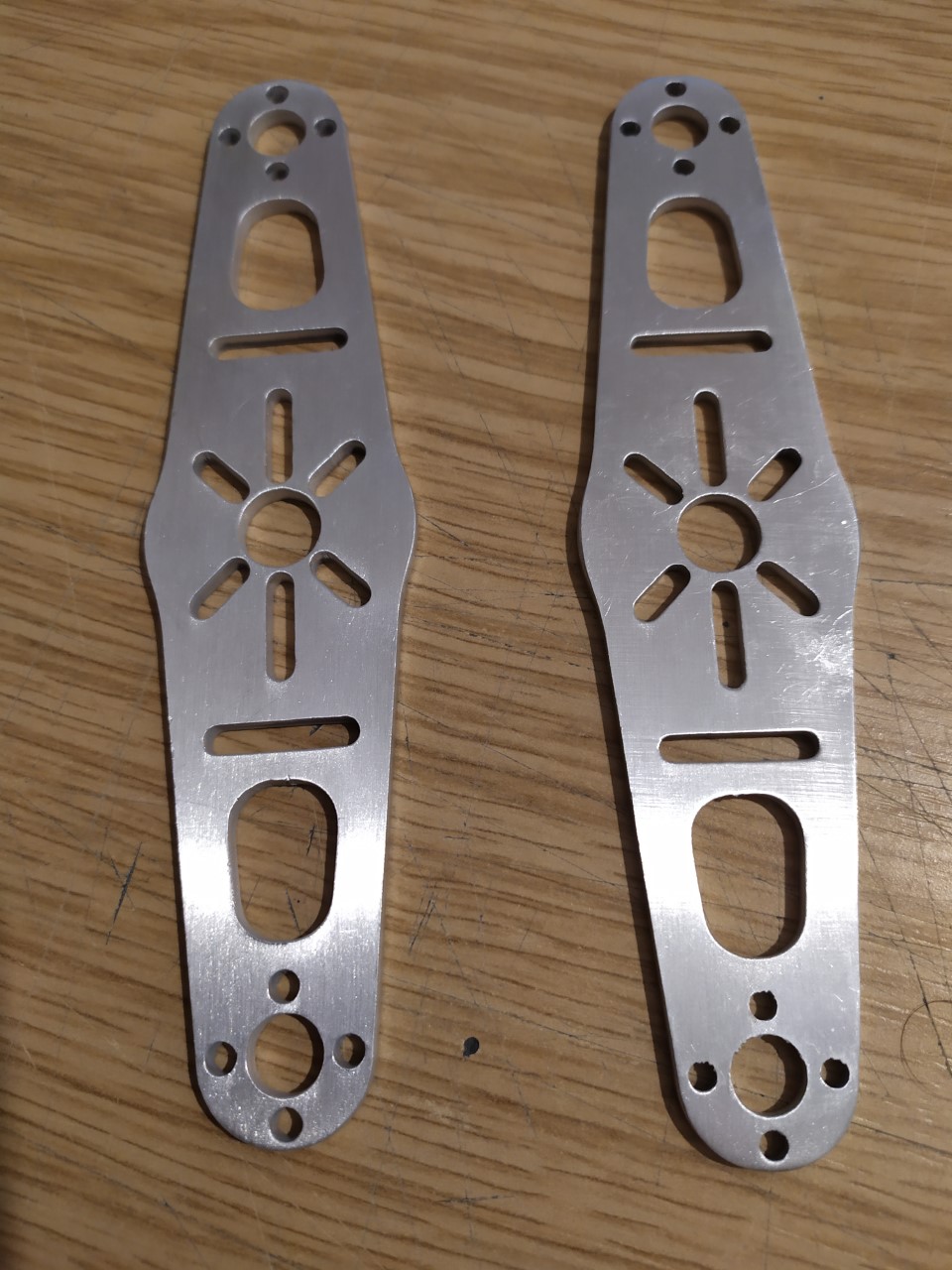
What I am really disappointed about are the tilt servo brackets that came with my kit (picture attached below). I just don’t know how I am going to get them bent/shaped precisely.
I must say that the build quality of the VTOL kit (specifically the VTOL upgrade) is rather poor, and I’ve had to do some unanticipated DIY work to fix a few disappointments.
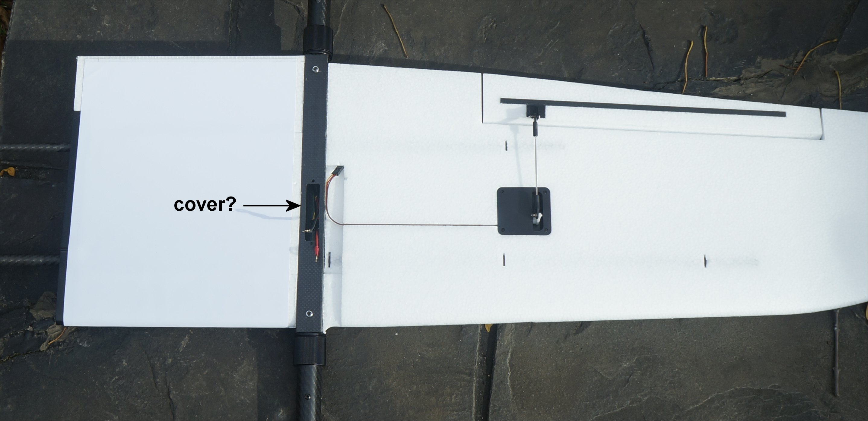
Yeah, that’s the one. I saw the mounting holes and just assumed there was a missing plate. Thanks for the explanation. Maybe we need a 3D printed cover here.
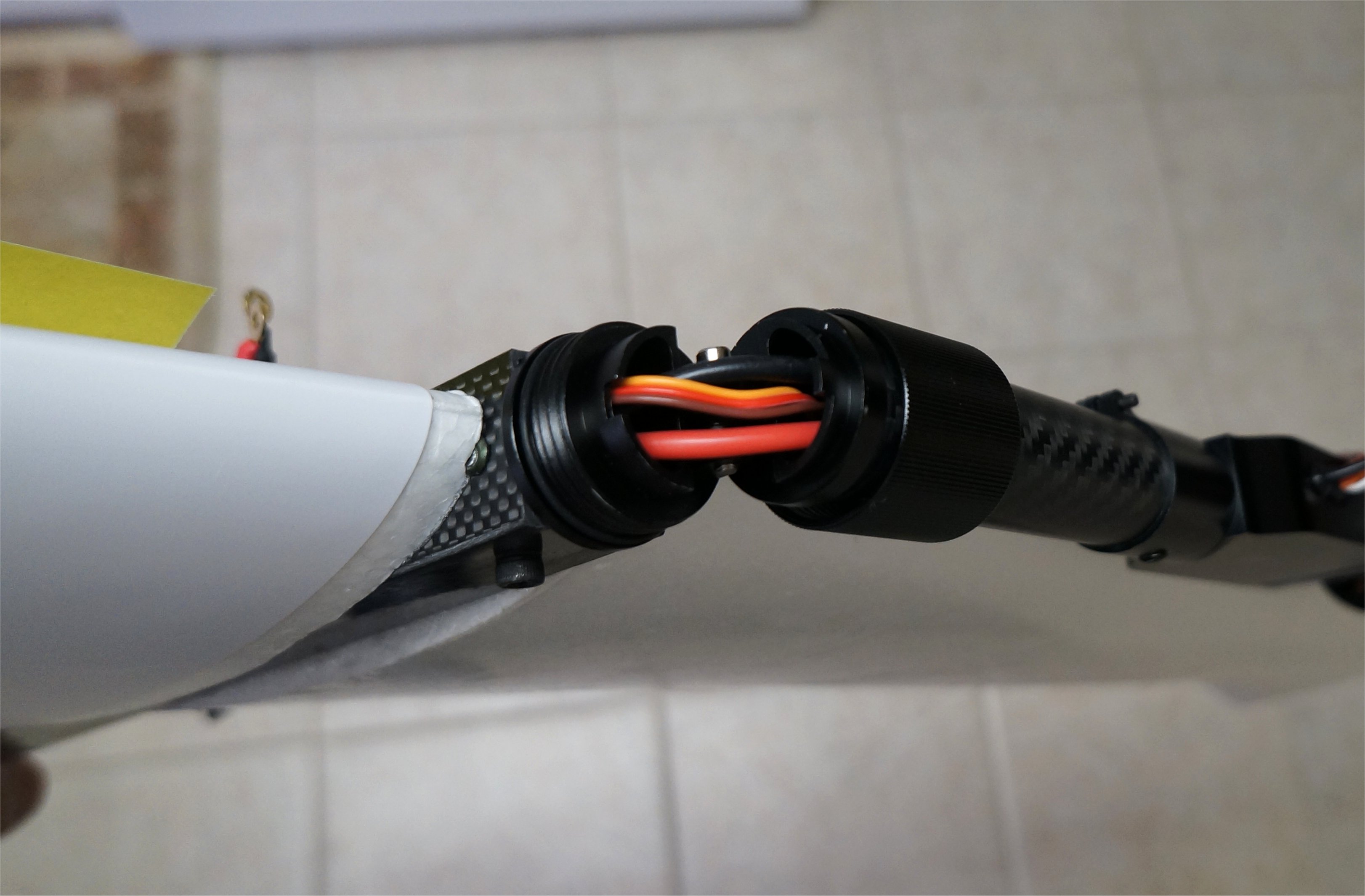
We used the same connectors when I worked for FMA Direct on the BalancePro chargers so they should be good for at least 60amps. Each motor should draw about 10amps in hover or 20amps total per connector. The pins are actually larger than XT60 connectors but I’ll see if I can find the connector specs.
I was thinking that by selecting vectored yaw, it would disable the torque yaw. Is this incorrect? Are you saying that on a quad configuration like the Freeman, with two front tilting rotors, we should disable vectored yaw and it will use torque yaw?
For covering that slot, I usually just cover it with lamination, since I laminate my wings anyways. My setups tend to be heavier than average, and I had some issue on the standard twin-tractor believer frames with wing flex and twist, so I don’t take chances with that.
For the connectors, since my planes are heavy, I know I pull more power. I know for a fact that I’ve hit as high as 120a (total, meaning 60 per connector) during transitions on previous frames. And, I don’t like taking chances.
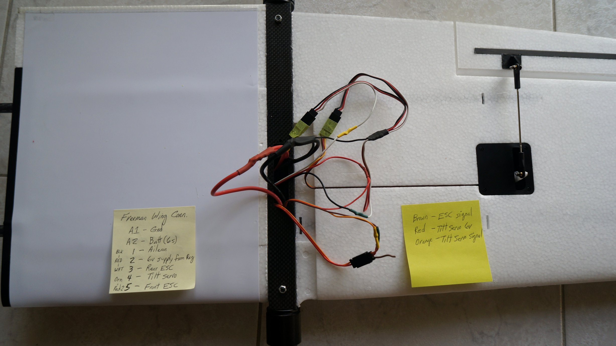
It’s also nice to have the front and rear wired separately, I can monitor power draw from each motor set as well as run separate batteries for front and rear. I suppose it’s not a requirement to do that kind of wiring on a lightweight build, but I prefer to have it.
For yaw, I will say that I prefer having vectored yaw enabled. Motor torque yaw is always on, vectored yaw just gets added on top of that. It doesn’t really “fight” the torque yaw, they actually work together pretty well, and having that extra control authority is helpful in pretty much any breeze. These planes have a decently sized tail, they really like to weathervane on you, trying to fight that with only motor torque can be a bit interesting.
One other advice on yaw: if you have’t already, set your frame type to X quad. Setting it to H causes some nasty frame flex when yawing or trying to hold a yaw in the wind. Basically, the frame flex creates an unintended vectoring of the thrust which is opposing your yaw inputs, and forces the flight controller to ramp up the yaw control to override it, which results in even more flex.
Greg, I did not see that slot because of the new landing gear. Now that I found it I am missing a cover too.
A flat piece of bass wood or carbon should be easy to attach.
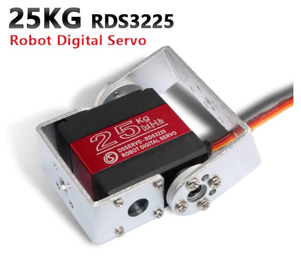
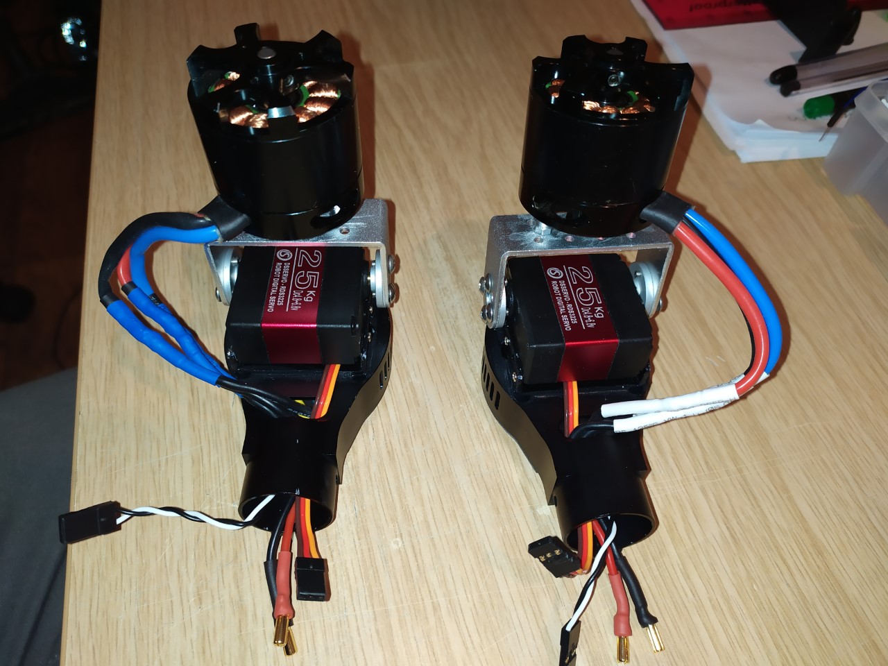
I discovered an interesting “gotch ya” when mounting my RDS3115 robot servo on the new style front mounts. Both the recommended RDS3225 and my RDS3115 servos have the control cable exiting the front motor side. On James’ Kuman servo, it has a removable connector for the control cable but it is also out front.
Are we running this control cable inside along one of the motor wire holes or drilling a new hole for it?
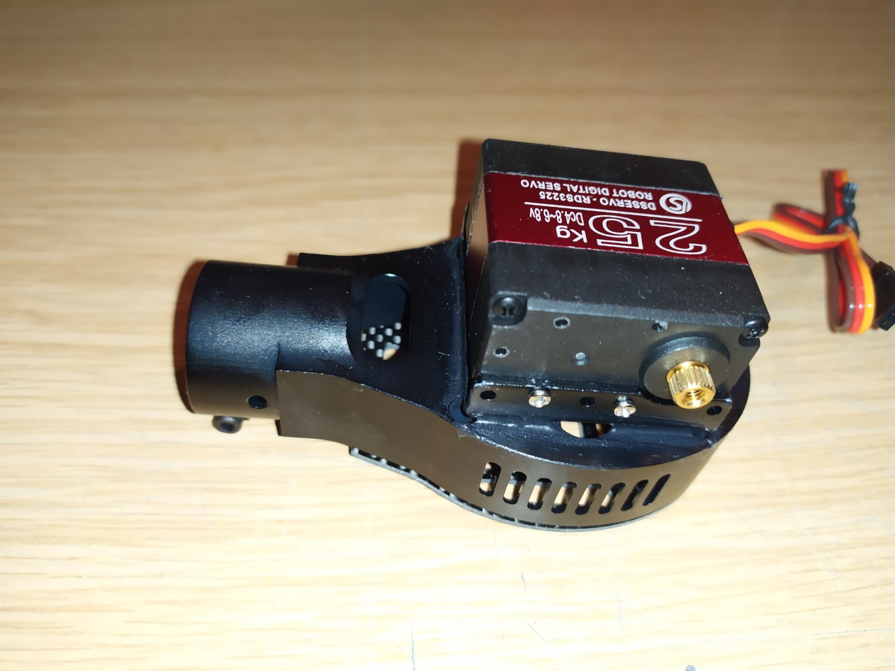
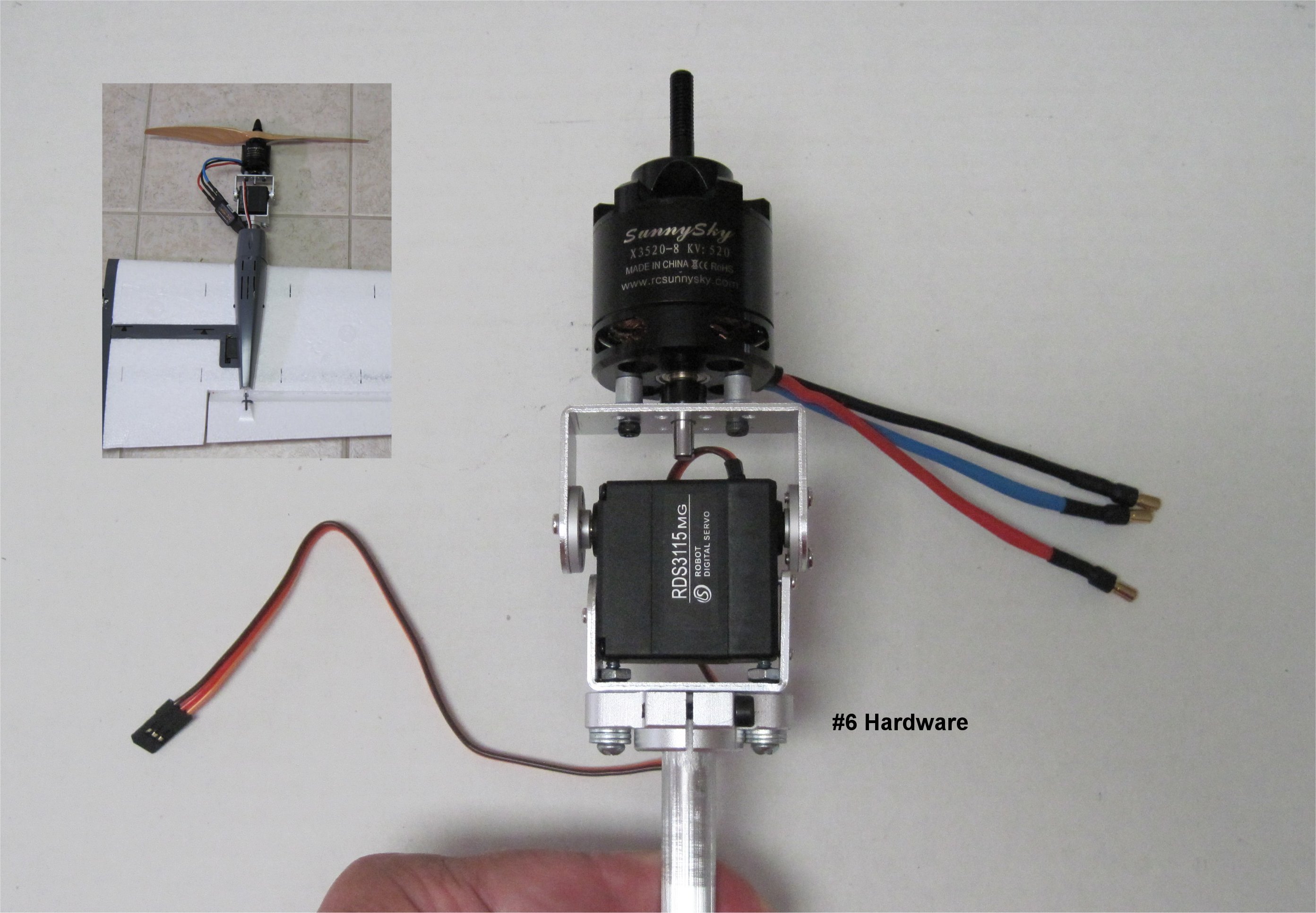
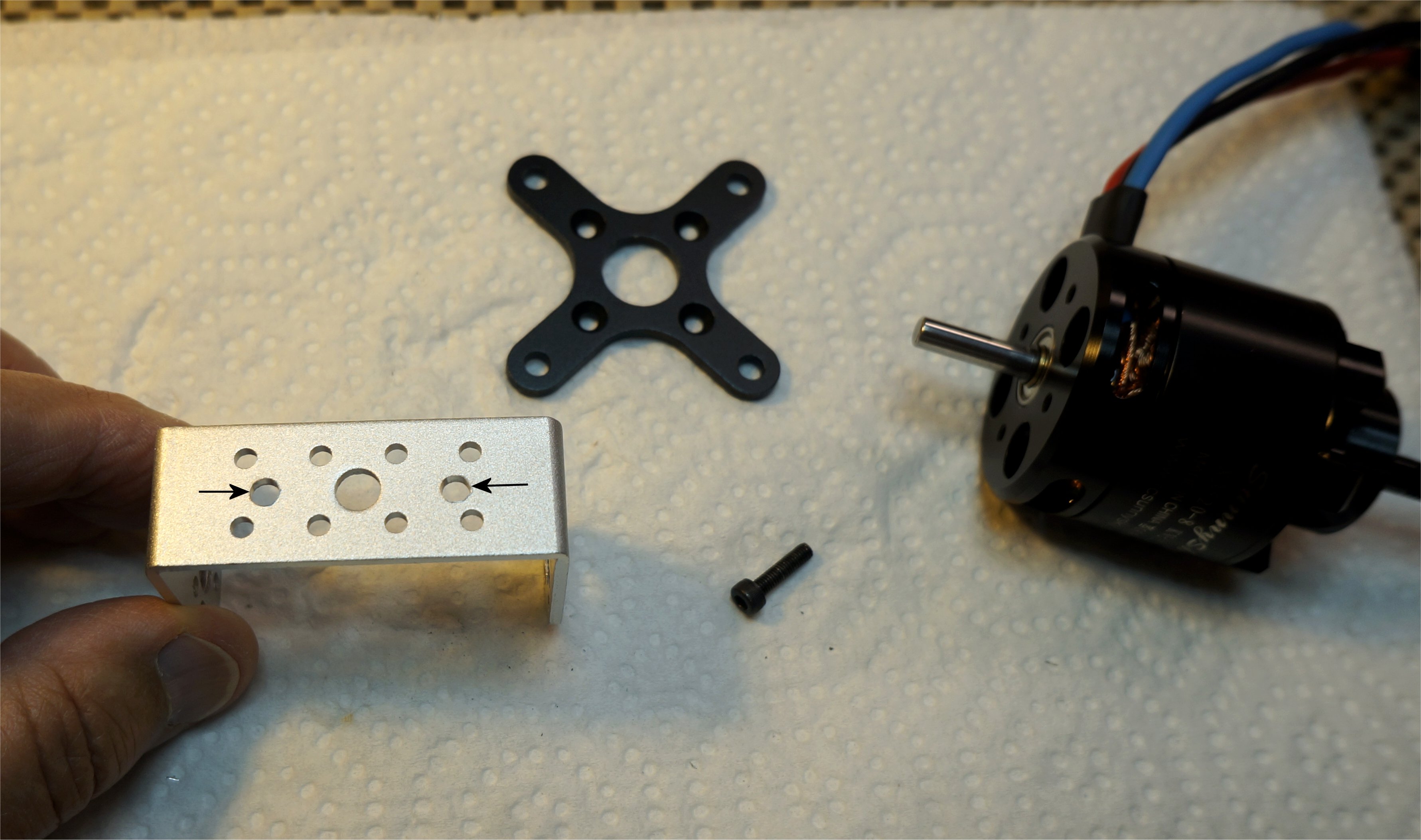
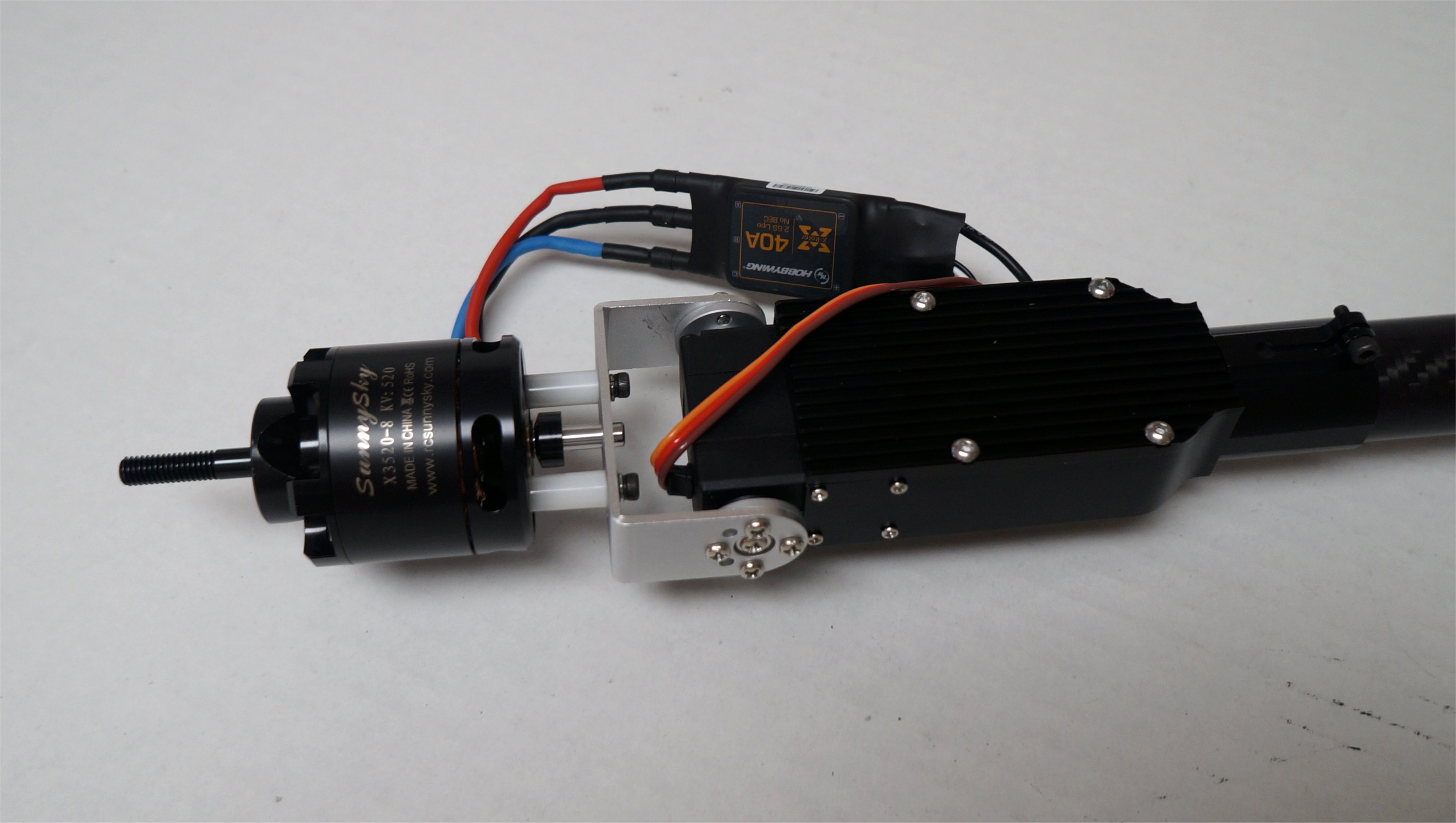
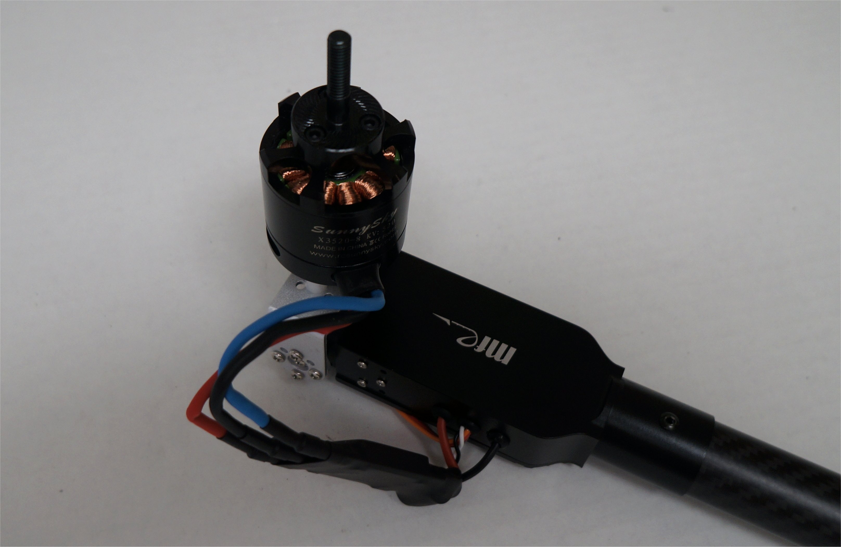
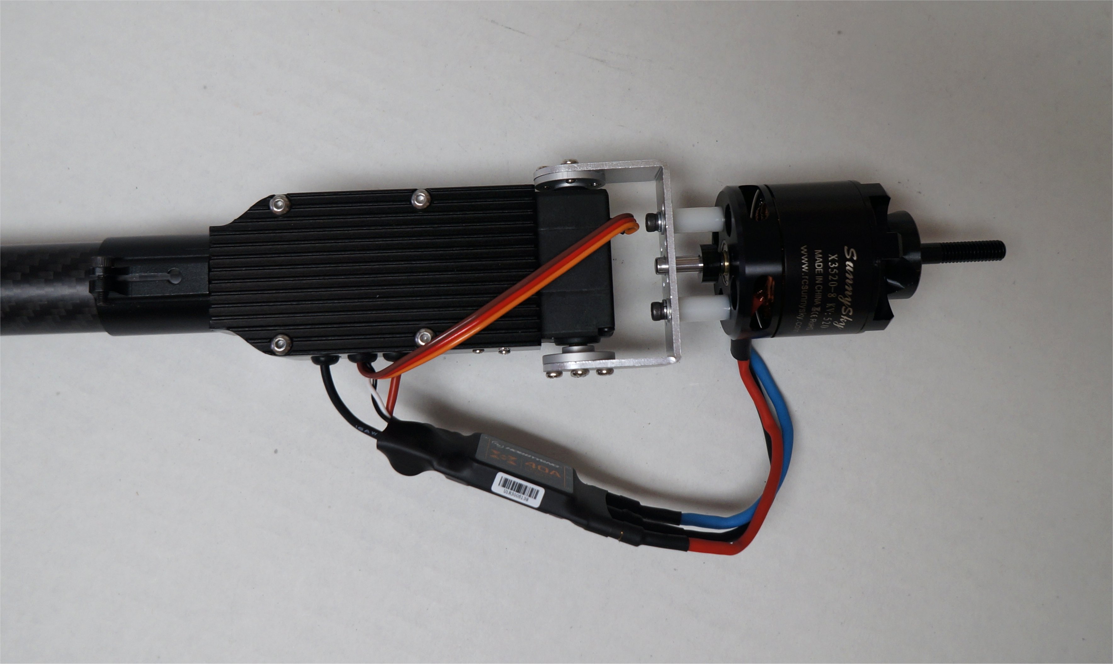
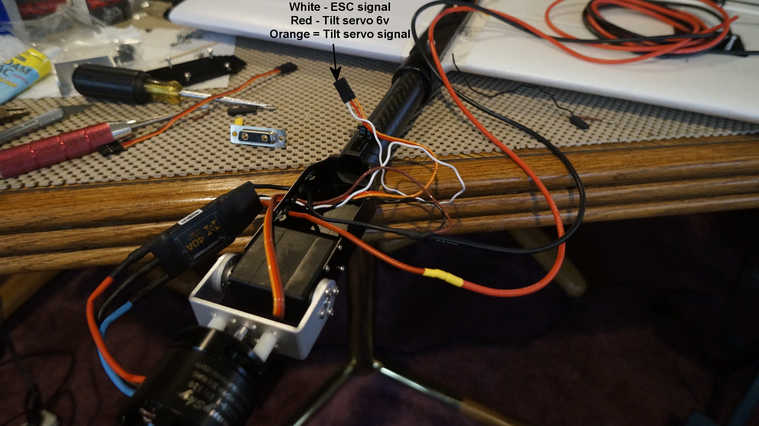
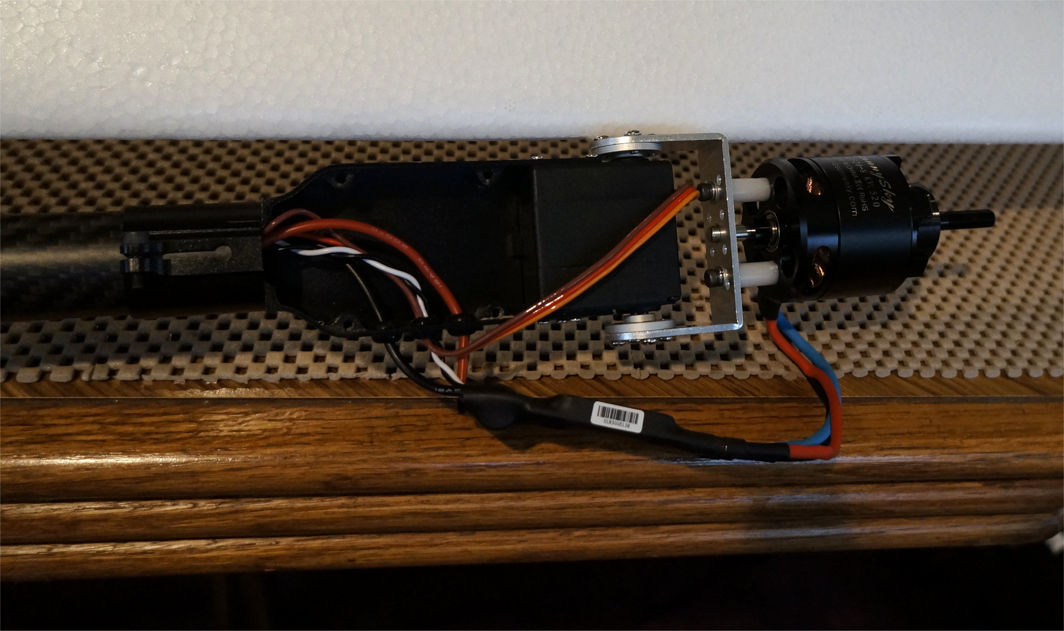
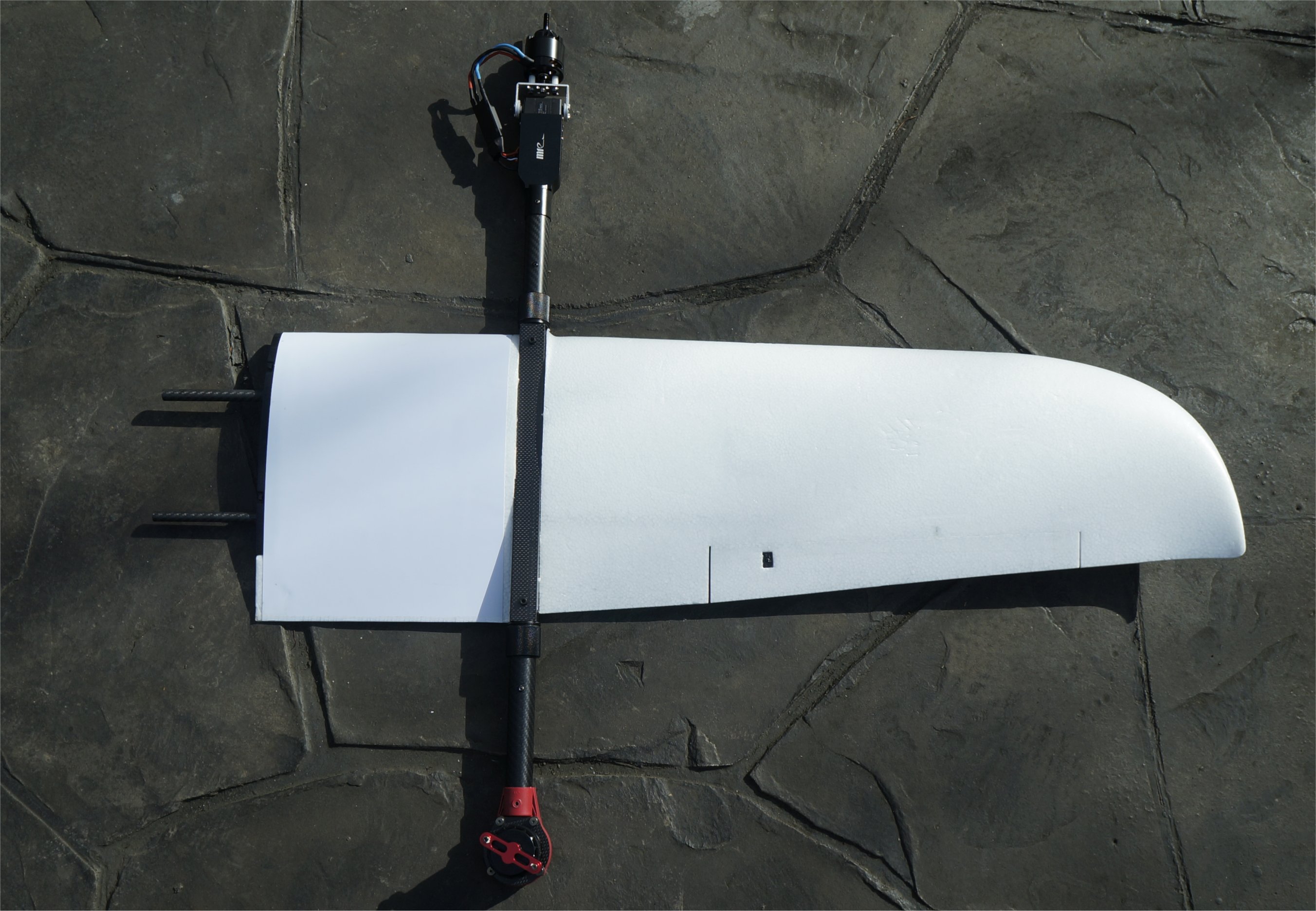
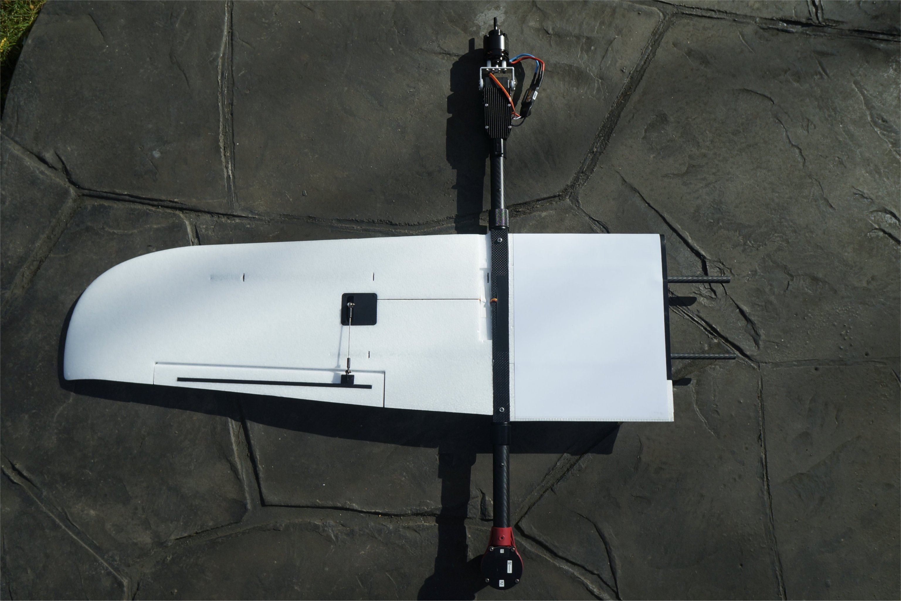
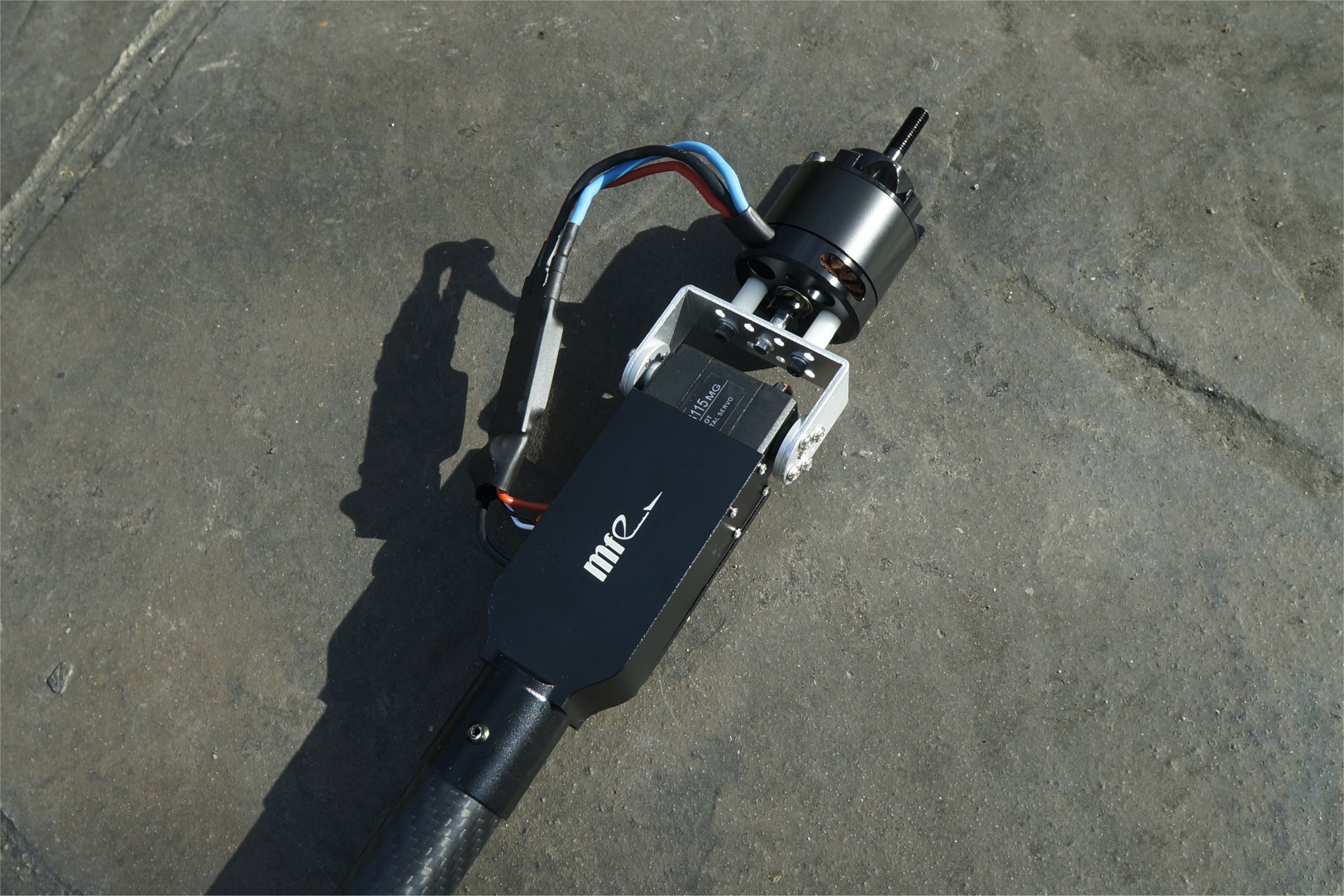
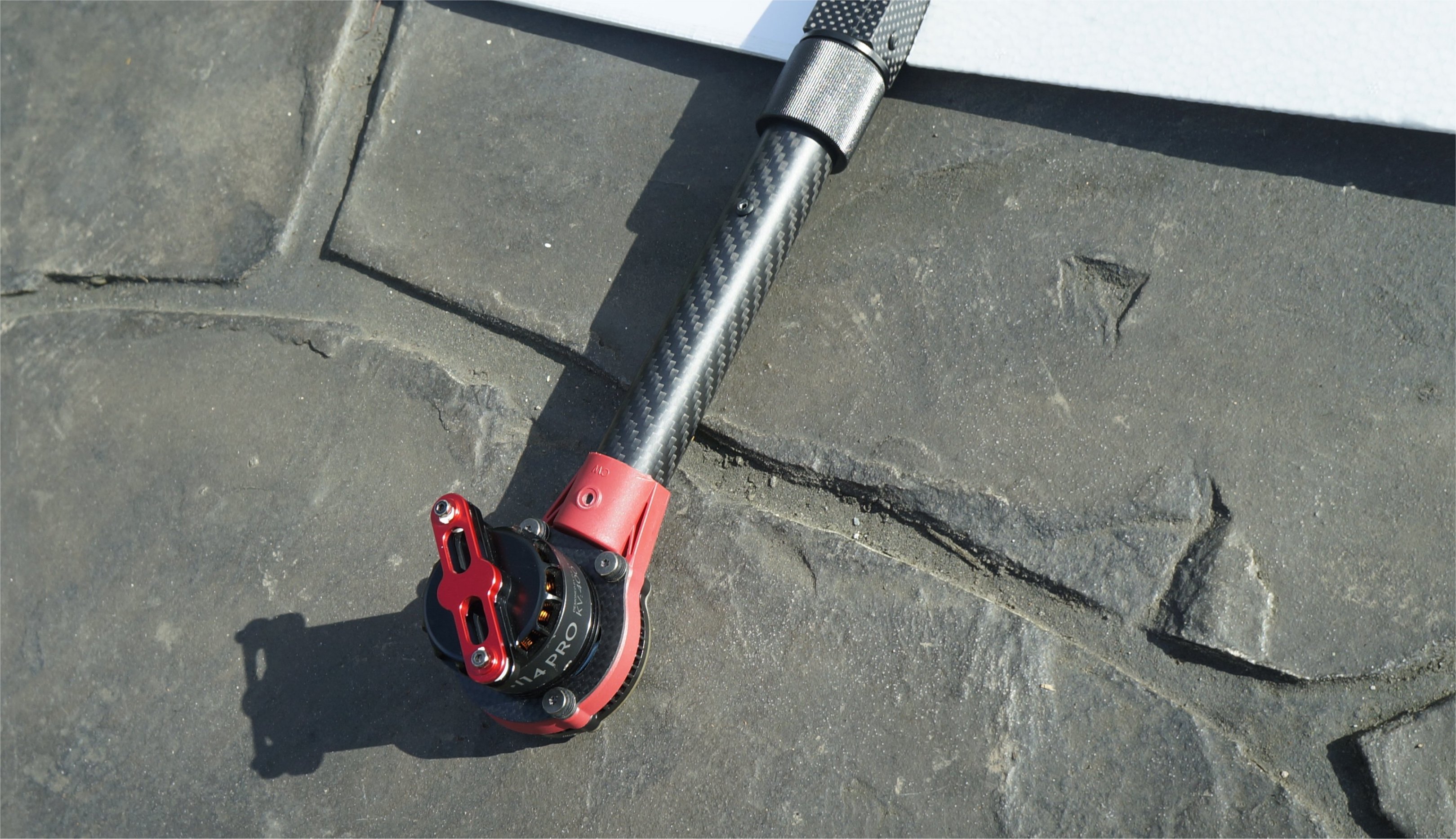
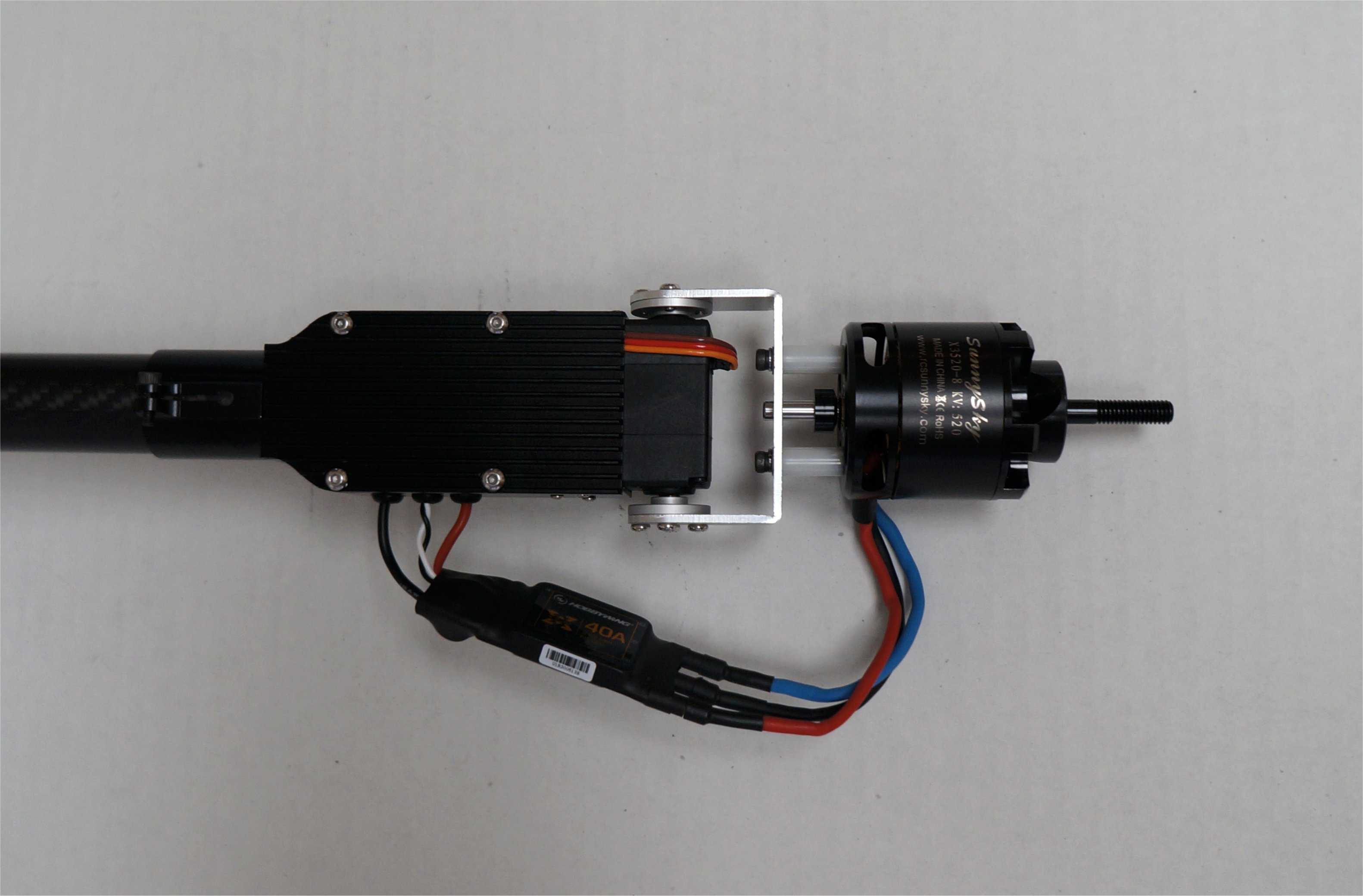
The first image below is how I mounted my motor and ESC on the Nimbus VTOL. Due to the long shaft on the rear of the version of SunnySky X3520 motors that I buy, I need to offset the mount from the bracket with standoffs. The robot servo bracket also does not match the motor mount holes so I drill new holes in the bracket using the x-mount as a guide.
The motor wires on my SunnySky X3520 motor are very stiff and short. The XRotor 40A ESC COB is a great ESC but it comes with only the 3mm female bullets installed without wires. I am not sure that this ESC would fit inside the front motor/servo mount anyway so I mounted it outside like on my Nimbus VTOL. Perhaps I will revisit this assembly down the road but for now I know it will work fine and no rewiring was required. I may order some shorter aluminum standoffs like in the Nimbus mount.
Hi Greg,
I’ve already got a few spare RDS3115MG sevos, which came with the mounting brackets. However, the hole spacings in these brackets don’t fit the SunnySky X3520 motors anyway. I guess my dremel will have to drill two new holes for me
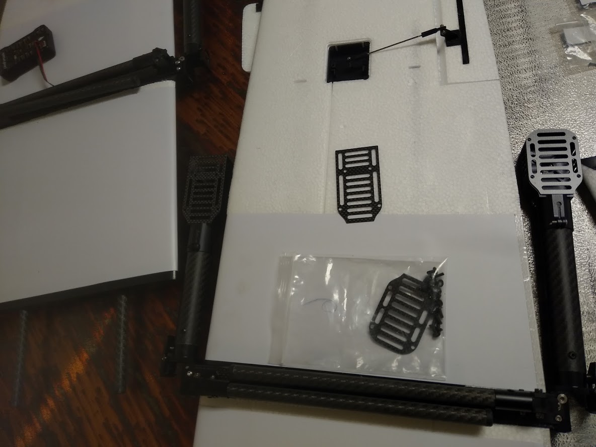
For some new airfames, which include metal motor mount backplates (they look like heatsinks):
There is a shallow channel on the underside of this plate, aligned with the location of the cable on the Kuman servos. The intent seems to be that one runs the servo cable back over the servo, through this channel, into the motor mount “box”. You may be able to do the same with your servos, for your airframe which included metal backplates, rather than running the servo cable over and around the motor mount. This would allow you to use the three grommet-bearing holes for ESC leads if ever you use a form-fitting ESC.
Some airframes however, such as that of @mtnsurveyor , seem to have come with a carbon fiber plate which does not have any such servo-cable routing amenity. Depending on how much of a gap there is, one may be able to fit the cable between the servo and carbon plate, or through one of the many holes in the carbon plate.
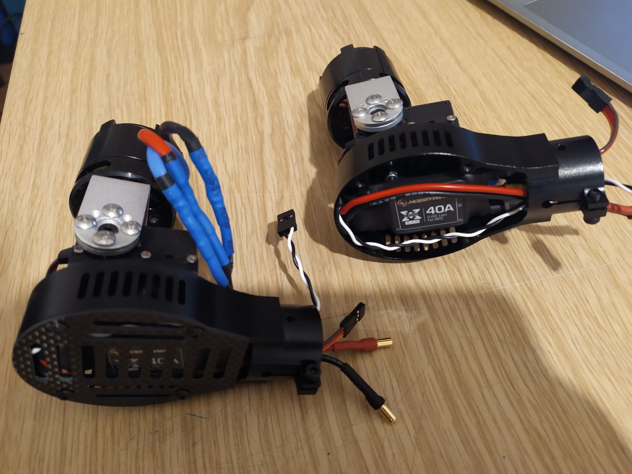
I am almost done with the wiring and I can confirm that XRotor 40A COB ESCs do fit within the front motor/servo mounts that came with my kit. I hope running the tilt servo wires alongside the front motor ESC and their three phase wires won’t cause any interference issues.
Greg, I think you’re using nylon standoffs (?), but I am using threaded aluminium standoffs. Although it feels very solid, I am just hoping that it’s not going to cause any vibration buildups. Anyway, be sure to use threadlocker to reduce any chance of self-loosening of the front motor mount bolts.
Your setup looks good. Those front motor mounts are the older ones so it seems the XRotor 40A COB ESCs fit better. On my standoffs, I used both Loctite in the motor holes and lockwashers under the hex screw head.
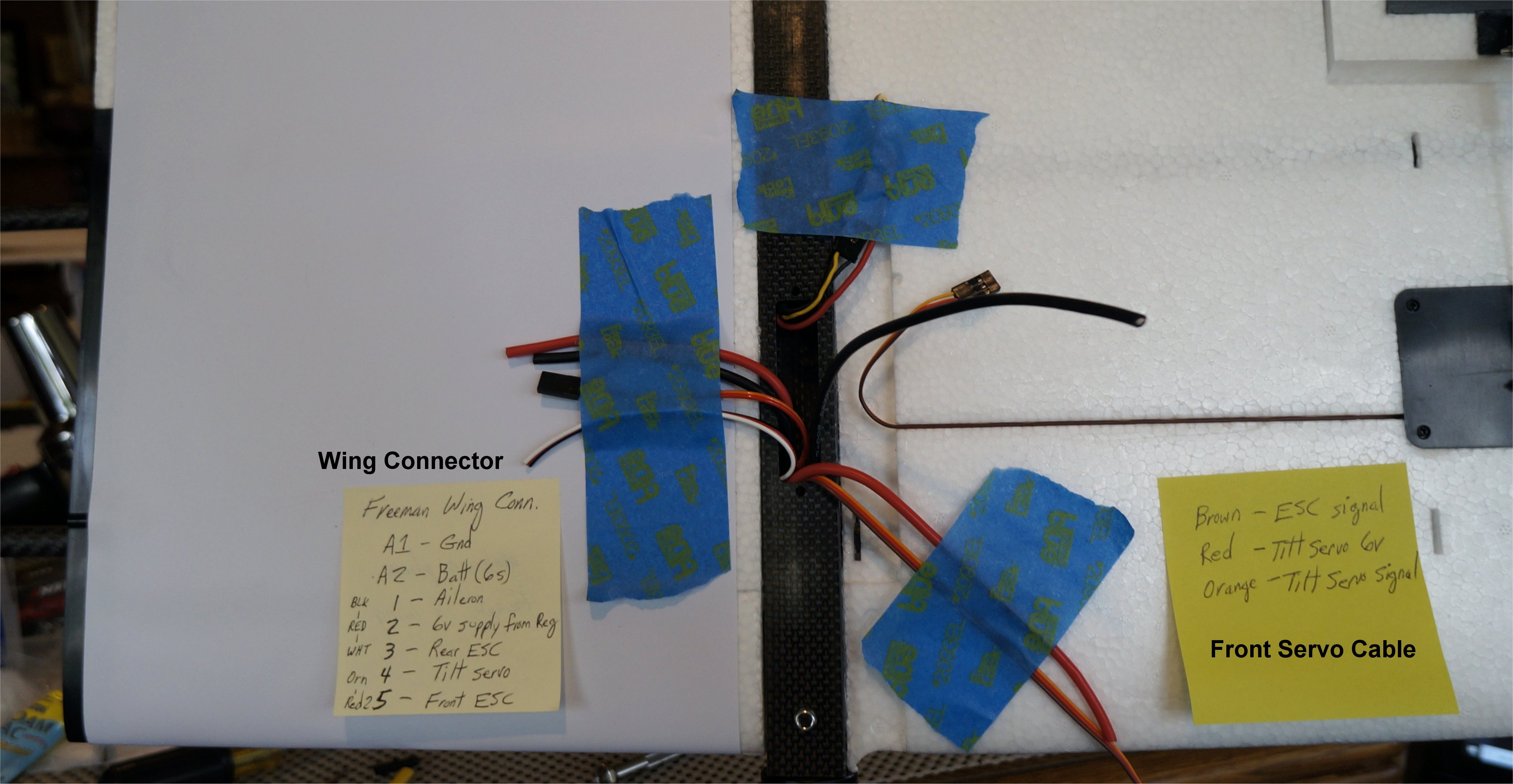
I discovered that by connecting all the grounds together at the front motor pod, you can run just a single servo extension to the center boom. It makes for a cleaner cable run where the boom bends at the elbow.
This would make more sense. I suspect that I have an earlier version of the heatsink cover without the channel. We are seeing variations in the parts as the design matures.
I finished the right wing wiring and it wasn’t too bad. There seemed to be plenty of room to run the wires and then stuff them inside when finished. For now, I just covered the opening with tape but plan to make some covers over the winter months. Using the DJI S900 Motor/ESC combination helped to simplify the rear motor installation as it just pressed into place and the cable assembly was long enough to reach the boom center. I’ll secure the DJI assembly with screws after my final alignment but for now they are held very securely. They can be found on eBay for as little as $75. We’ll see how it works out.
I plan to use the same 13x8 Wooden Propellers on the front motors that I used on my Nimbus. I need some rest before I start the left wing.
If you want, you can PM me your email address and I’ll forward it to Mr. Chang. Perhaps your server will allow the address coming from the other direction. You are not the first person to have this issue.
Thanks for the tip! I took a second look at my motor mount back plate (with my readers on) and saw the channel so I updated my tilt servo wiring for a cleaner look. Sometimes it sucks getting old!
I was looking at the 0960 model which was supposedly RTF and was the same as the Freeman 2300 standard version. As it turns out Mr. Chang said they where the same so I assumed that meant it was prebuilt as well. I ordered the 2300 Standard Version directly from them it comes in 2 boxes of which I have only received 1, todate the 2nd box I think is stuck in our custom service. Mr Chang has been very helpful but his english and my chinese have made things take a lot longer to get it done. They have offered to guide me thru the build process. I have a configuration list that is in English if any one would like .
Jim