I agree with Wasim that using an X-frame (Q_FRAME_TYPE=1) is fine. It should also be equivalent to use an H-frame as long as the Q_FRAME_TYPE is set to 3. I haven’t noticed any difference in my VTOLS but my Freeman 2100 will be set to an X-frame as shown below.
MickeM and Curt,
I also had some surface damage on mine so I have reported this issue to Mr. Chang. I can live with mine but if you can’t then please send photos to him at 2565710339@qq.com.
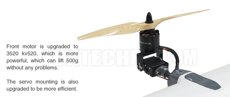
I haven’t gotten to installing (or even ordering) the front motors yet but it will be similar to the Nimbus VTOL. You can browse that thread for details or see the image below. The reason these motors are used up front is because they perfectly fit the 6mm holes in the higher pitch props. Remember to replace the stock motor prop screws with self-locking (nylock) nuts.
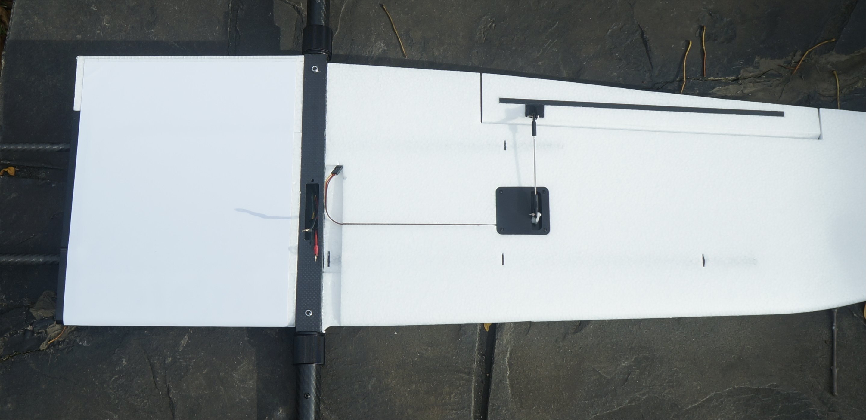
After centering the servos with a servo tester, I installed the servos and linkages on the tail and one wing. The design made for an easy and secure linkage that won’t come off. While one of the tail fins snapped into place perfectly, the other required just a small amount of Dremel work on the swiveling part before it would seat properly. There was no wobble in the control and the 2mm hardware fit perfectly!
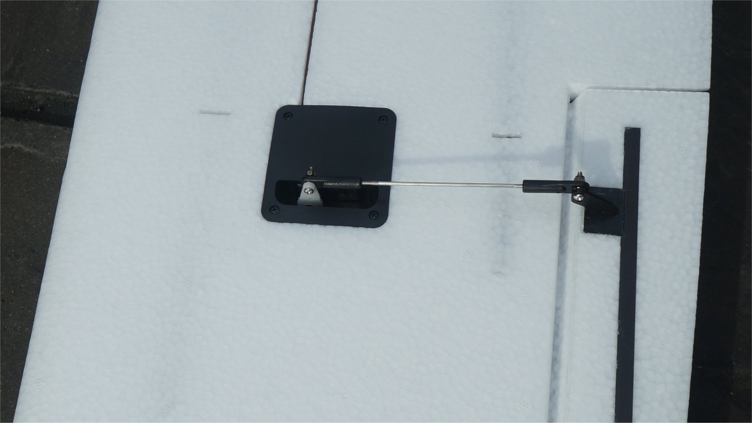
The recommended Emax ES3054 servos fit perfectly in the tail and wing servo box. For the tail, a custom part was supplied to screw onto the circle arm supplied with the servo. However, for the wing servo, there was no proper arm supplied to mate with the 2mm linkage hardware. I used the four arm piece and cut three arms off. This also required good trimming to fit in the box without scraping the bottom. Lastly, the holes on the Emax ES3054 servo arms are smaller than 2mm so I carefully drilled the top hole to allow the 2mm screw to pass through. On future designs, it would be nice to eliminate this manual assembly by supplying a proper arm for the Emax ES3054 servo with a 2mm hole.
The wing servo is secured nicely by a holding arm and cover plate. It looks professional and makes it easy to replace the servo, if needed.
Thanks Greg. This is very helpful, When you get to the front motors I would like to see it. I do not find any hardware to make this work in the kit. Was it included in yours?
The hardware should come with the tilting robot servo. My kit did not contain the PNP components so I will likely use the RDS3115 15kg robot servos that are working well on my Nimbus VTOL with the same motors as the Freeman 2100/2300. I also have the 28kg Servos from the Foxtech Nimbus VTOL V2-Tilting System but I doubt I will need that much torque at 6v. The RDS3115 15kg robot servos are half the price of the RDS3225. It’s a DIY builders choice.
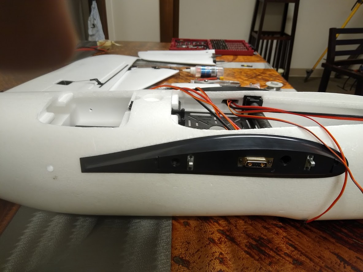
I will use the following pinouts as defined in the Freeman Wiring Diagram for the wing connectors. The male connector is on the plane and the female connector is on the wing. I will supply 6v from a regulator inside the fuselage instead of 5v.
I received a reply from Mr. Chang reporting that all the parts are inspected multiple times for indentations and dings before shipment and there have been no issues reported within China. The assumption is that international customs is scattering parts or bags when the box is opened for inspection and not properly repacking them. This makes some sense to me as I had several parts floating around inside the box foam with cut tape.
I had to laugh because I saw a “Portable canvas bag” in the kit parts list but never found it. After pulling the bottom foam piece from the shipping carton, there it was taped in its own compartment. This will make it easy to store and transport the Freeman with protection.
I don’t care about the minor EPO damage but its there. Both wings have a similar mark & all the marks are smooth and sealed. They appear factory most on the right wing.Its a tough wing that will see many larger marks in its life. https://1drv.ms/f/s!AsVDYQvUKHCO8iKucyvU4Prs6Cvx
A 6v supply gives the tilting servo arms more power and doesn’t hurt the Emax ES3054 aileron servo either. Both can safely run on either 5v or 6v. The goal here is to provide sufficient current (5amps per wing) to the tilting servo for proper operation under load. The limited number of pins on the connector forces us to use 6v for the Emax ES3054 aileron servo…which is fine.
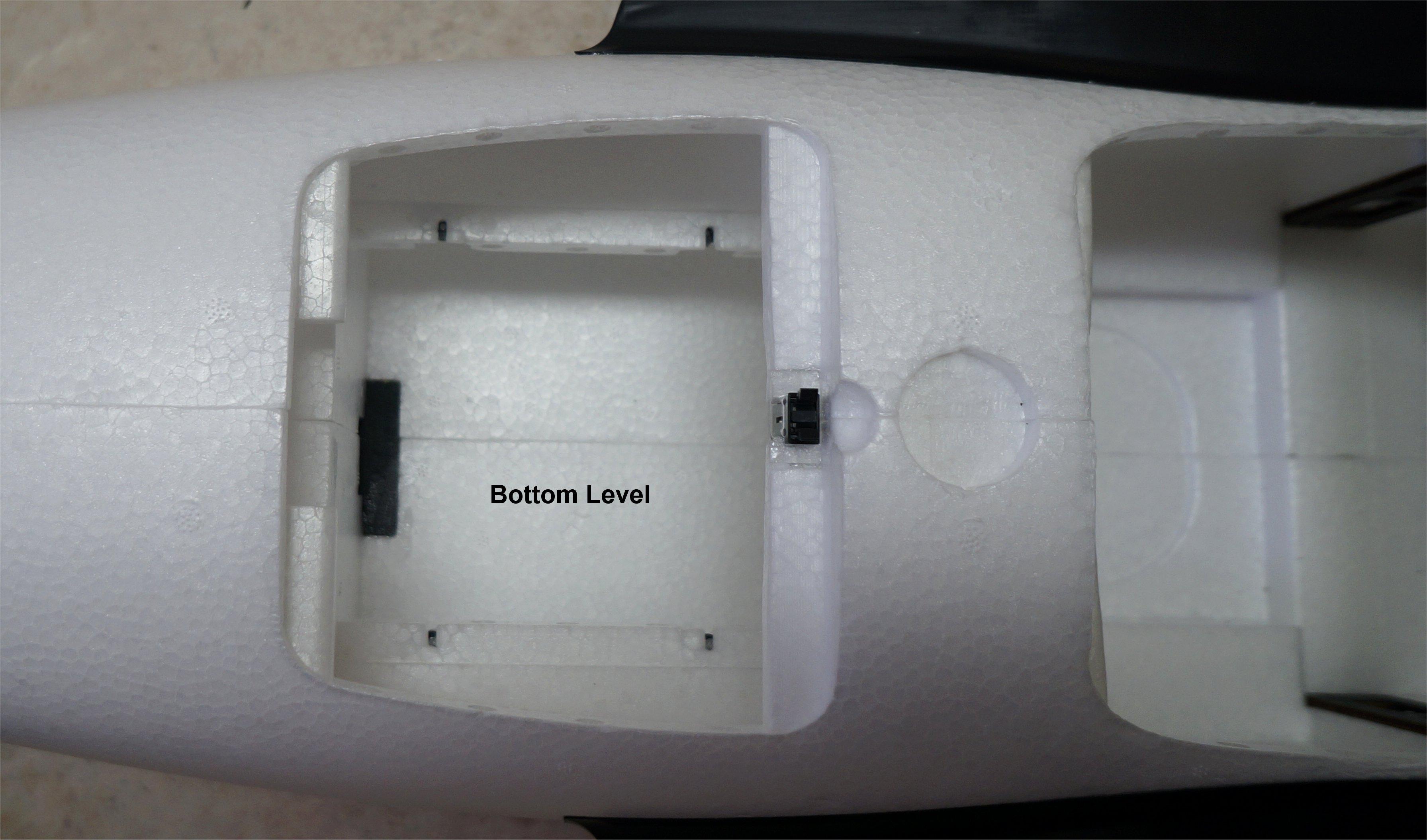
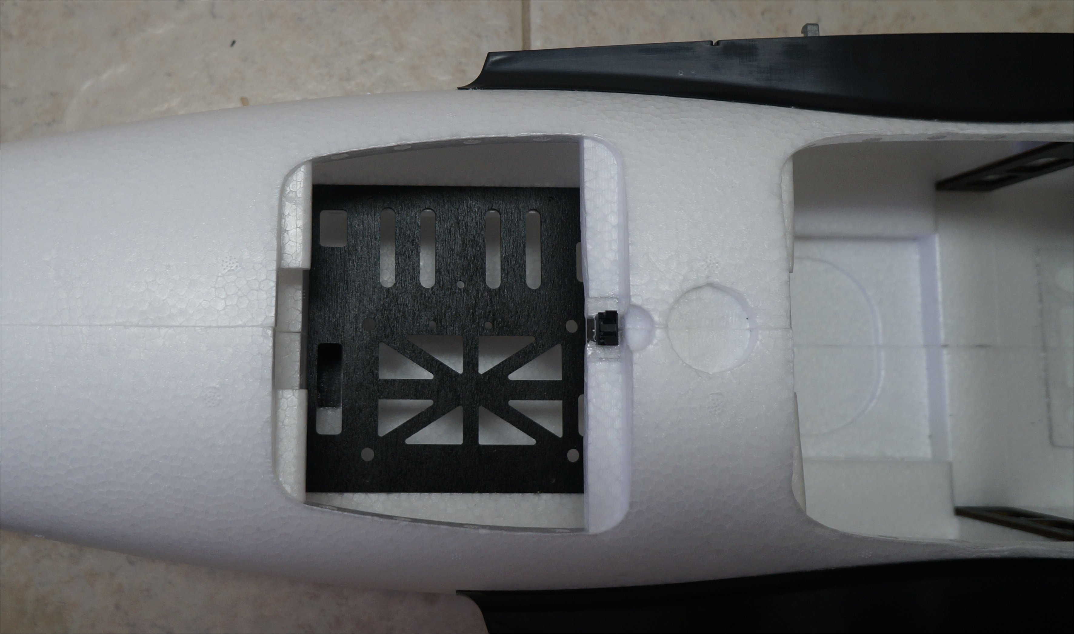
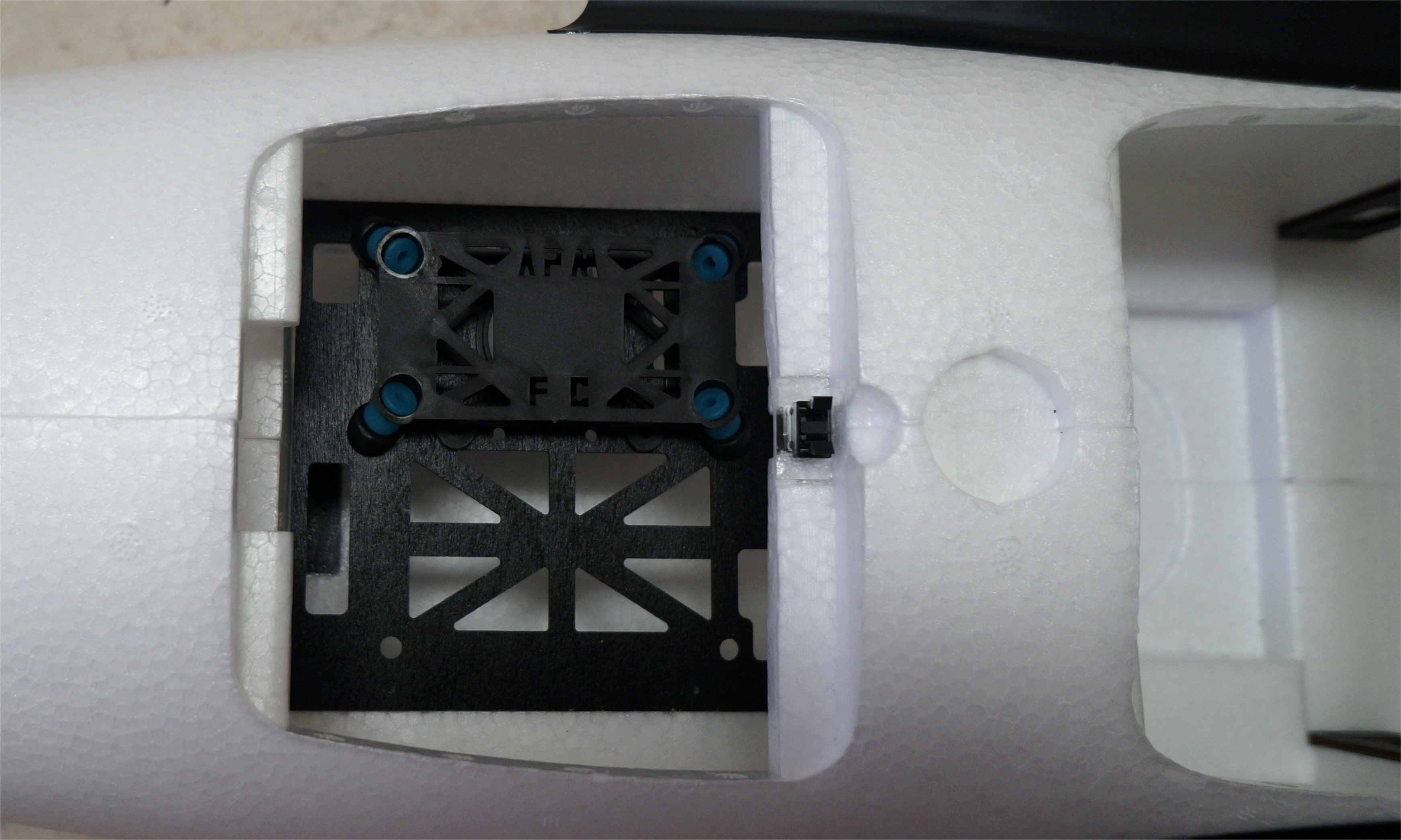
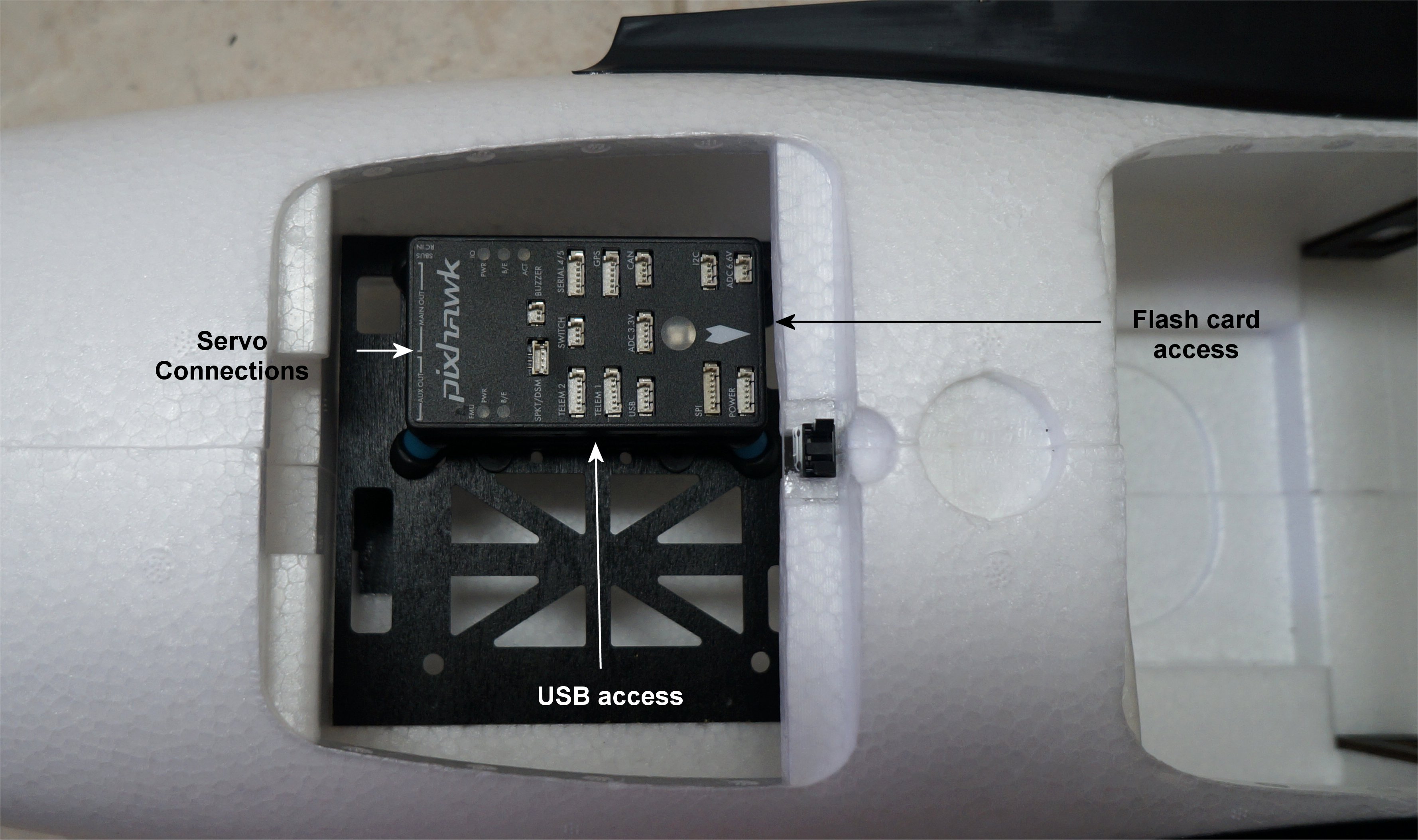
I decided on how to mount my Pixhawk controller. By using the second level of the top middle cabin area, it allows for easy access to the USB port, flash card via the front cabin, and servo connectors. There is still plenty of room between the Pixhawk and top cover. (I do love these push-lock covers!) It also keeps the lower level free for other components as I do not use the Pixhawk on-board compass. The slightly off center axis mount will have no effect on performance…at least I have never encountered any. From the Wiki:
It is not critical that it (the Pixhawk) is placed exactly at the middle but closer is better (there are no recorded cases of problems caused by the controller being far from the centre of gravity).
I was hoping that others were building a Freeman and could post their photos. While I wait for my front motors to arrive, I started to install some components in the fuselage. I ordered my two Sunnysky X Series X3520 520kv Brushless Motors from Buddy RC.
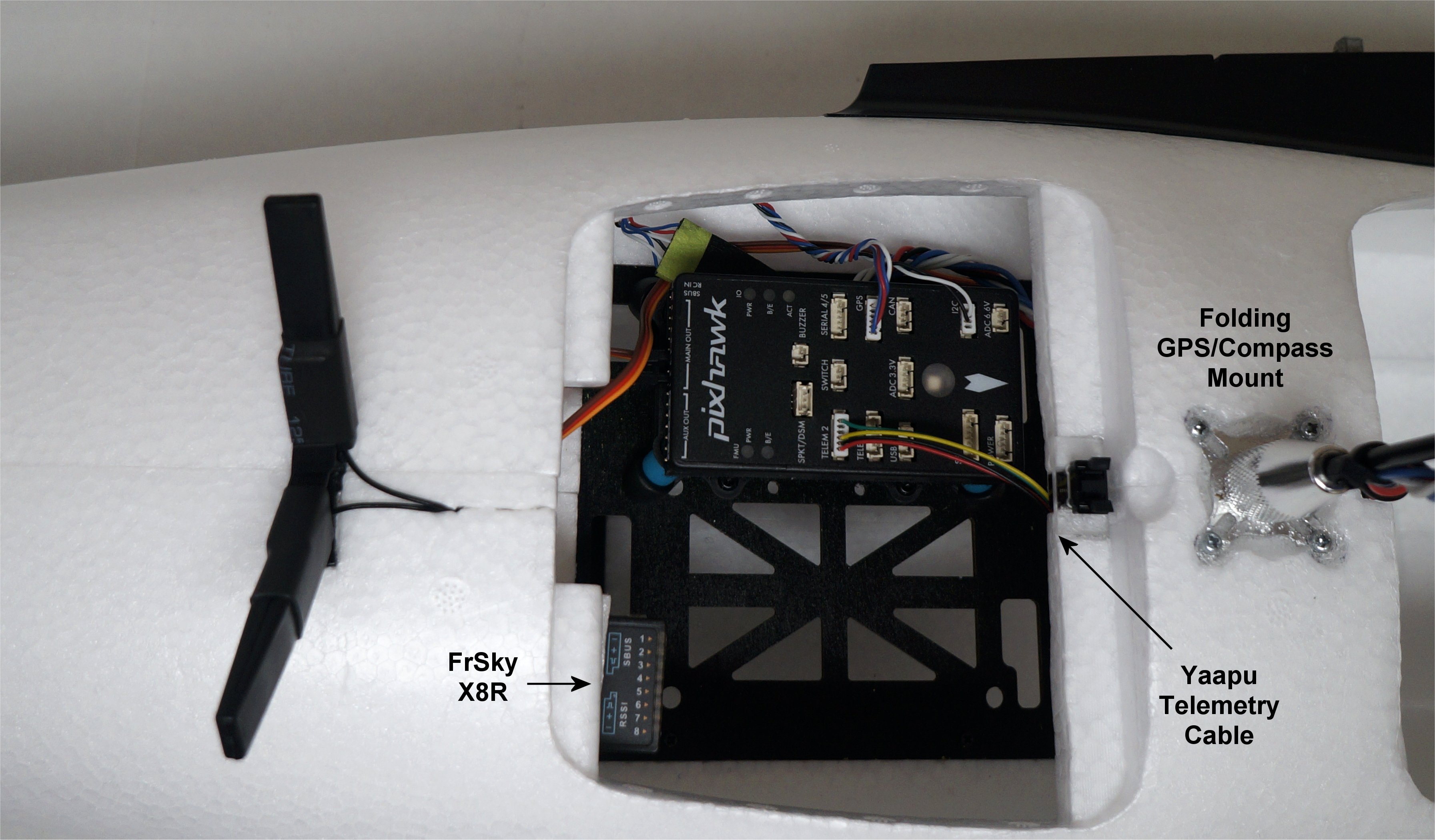
It is always fun to plug the first item into the Pixhawk, which in my case was the v-tail servos on Outputs 2 and 4. I also added a FrSky X8R receiver, Yaapu telemetry cable between the S.PORT and Telem2 port, and a folding compass mast. The exposed X8R outputs are for camera controls.
Details on the Yaapu telemetry script can be found here and here. My M8N GPS module is a high quality design originally from the CSG Shop in Latvia. It has the compass on the bottom side. Today, the company is known as the GNSS OEM Store. I decided to keep the folding mast on for now so it is raised above the FrSky telemetry and video transmitters.
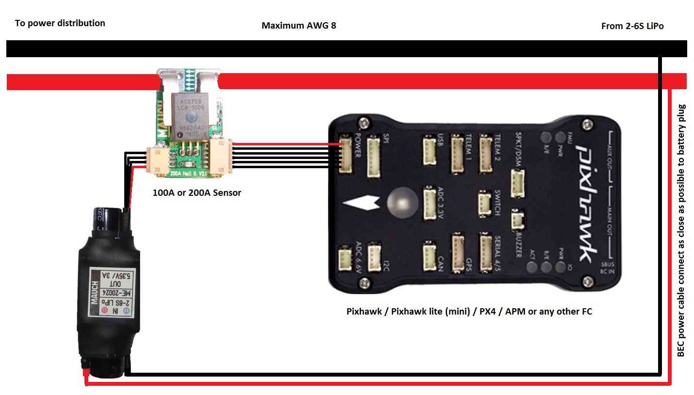
I also decided to use a MAUCH Power Module on this build because of the increased accuracy for voltage and current measurement. In the U.S., you can buy them from Craft & Theory. They are also available direct from the manufacturer here.
Thanks, Curt. Those annoying Tips that show up on the threads suggested that I am hogging the thread.
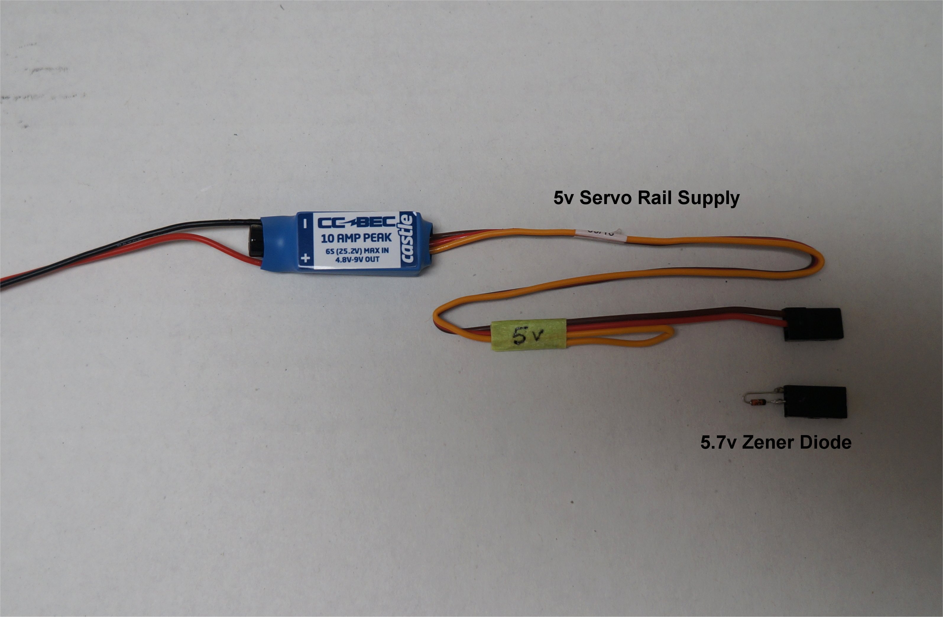
My Pixhawk servo rail (Main and Aux Outputs) will be fed by a CC BEC set to 5v. By also using the 5.7v Zener diode, I will have a safe redundant supply to the Pixhawk Power Module. There is more information on this in the Powering the Pixhawk section of the Wiki. For the 6v supply to the wings, I’ll be using a CC BEC Pro set to 6v.
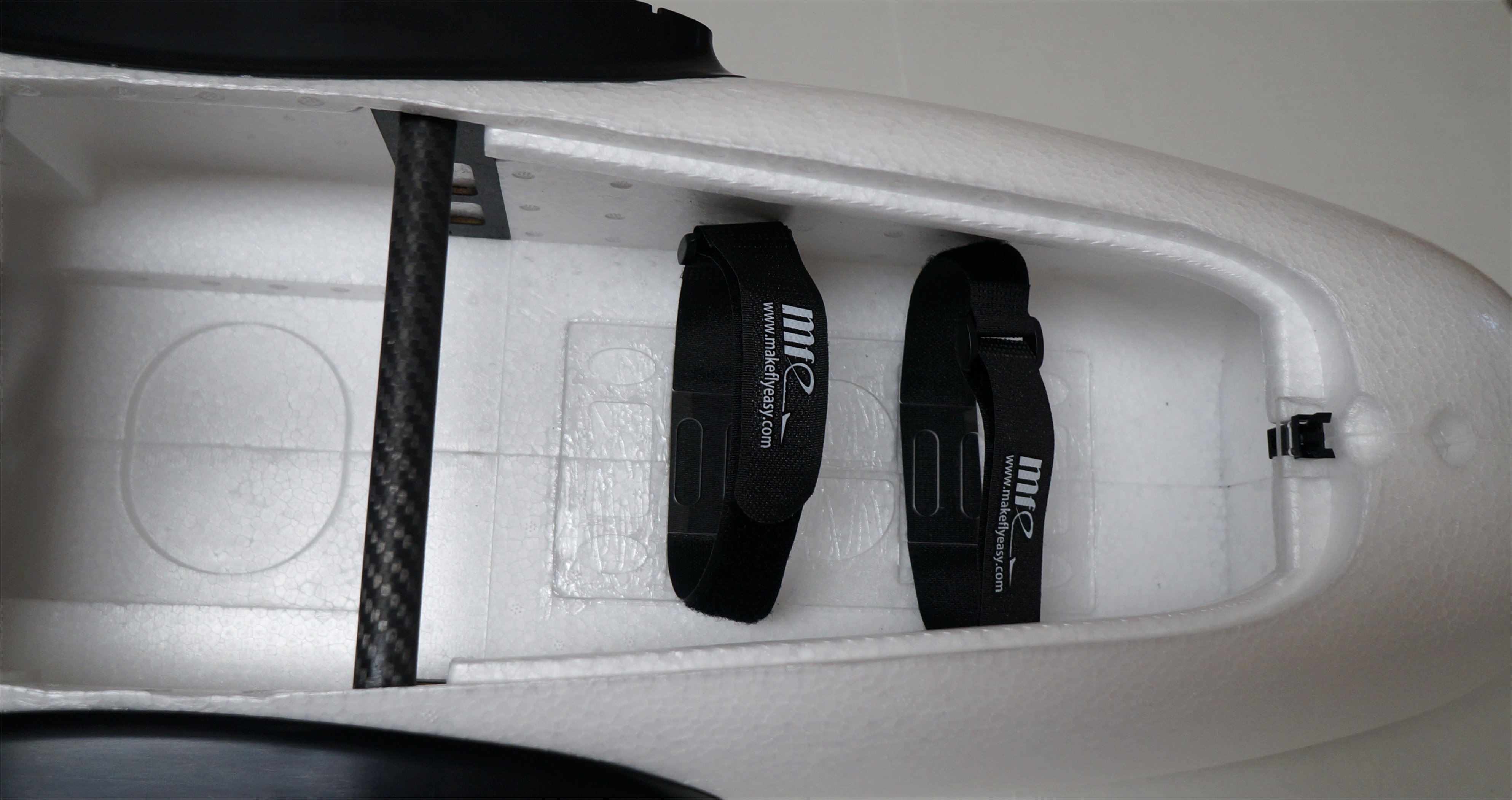
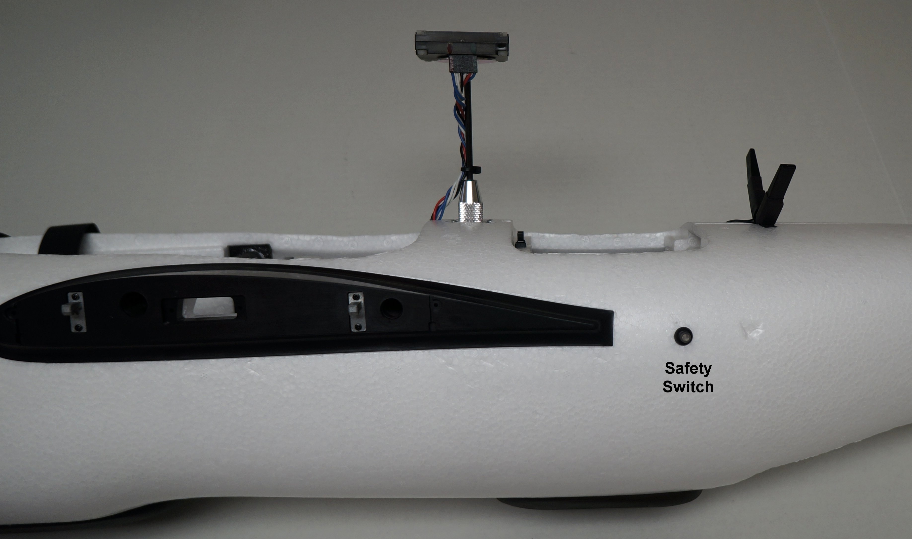
Even though my setup has the switch set for for automatic enable (BRD_SAFETYENABLE=0), for now, I decided to use and existing hole in the fuselage for the Safety Switch. It fits perfectly and there is one hole on each side behind the wing. I’m not sure what they are meant for. To the right of the Safety Switch, you can see one of my “dings” in the fuselage that I’ll add some Foam-Tac to later.
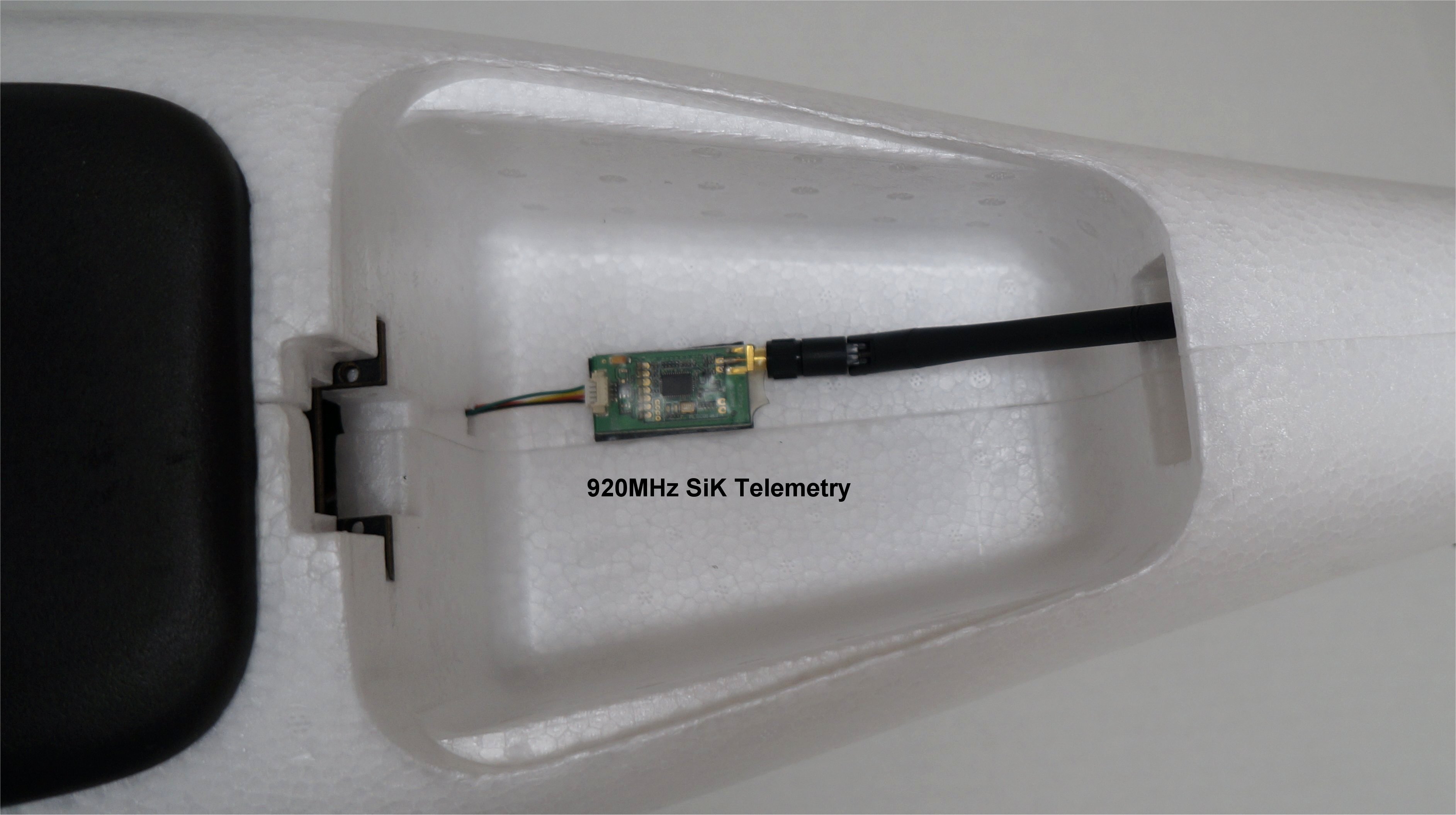
My 3DR SiK telemetry radio is simply mounted in the large parachute opening. I still haven’t looked into how to hold the bottom cover on.
I attached my initial .param file for the Freeman. I have set up the proper frame, class, and tilt yaw setting as well as tested the v-tail. Since this is a QuadPlane setup with tilting front motors, I am curious if we are allowed to choose between vectored yaw and rotational yaw. FreemanBuild2.param (17.0 KB)
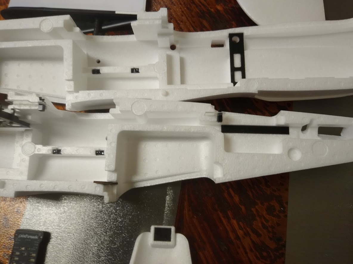
I received some new 2100 and 2300 frames, the motor boom assemblies are clip-type on both sizes. I think we can assume that all 2100 and 2300 frames from here on out will have these clip locks. As far as I can tell, this should be an improvement, this new style of clip shouldn’t be susceptible to vibrations like the older screw type ones were.
The 2300 has foldable landing legs on the bottom of the wings, but both sizes have the mounting points for them so you could probably get a 2100 with them if you want.
The other major difference with the 2300 is the inclusion of a ventral fin, to be glued on to the bottom of the fuselage. The fuselage itself has not been modified, meaning that there are no alignment pins, tabs, or holes to get the fitment right. I’ll have to be very careful when gluing that fin on. It’s also worth noting that I’m 99% sure that this “new” fin is simply a trimming from an extra Vtail. It keeps with the theme for these planes, “Take a standard Beleiver frame and kit-bash it into a VTOL without actually making new molds for the foam.” You may notice the cardstock-wrapped sections on the wings, peeling that back would reveal multiple pre-existing and trimmed sections joined together to get the desired shape. I do hope that a future version of this frame will have real molds for the new parts and thus lose the extra weight of the glue and cardstock.
One point of improvement on both frames is the new style of motor/servo mounts on the booms. The previous version of this frame, the “Freedom 2100”, included a rounded style of motor mount for both the front and the rear motors. it was fine for the rear, but there was zero provision for servo mounting in the front, and I had to use files a dremel, and JBweld to make the servo brackets fit. The new version come with rectangular mounts, and the front mounts include provisions for tilt servo mounting. Using a servo with the reccomended form factor, it will simply attach with the screws included with the servo, no modification required.
Here’s an Imgur Link to some pictures of both frames.
Thanks for the photos! My Freeman 2100 has the new front motor mounts but the older screw type arm latches. I’ll just use some tape to hold them in place for flights. I didn’t get any covers for the rectangular opening in the bottom of the boom. Can you post an image of the cover?
My motors and ESCs arrived today so I have plenty to work on now…including the dreaded wire harnesses.
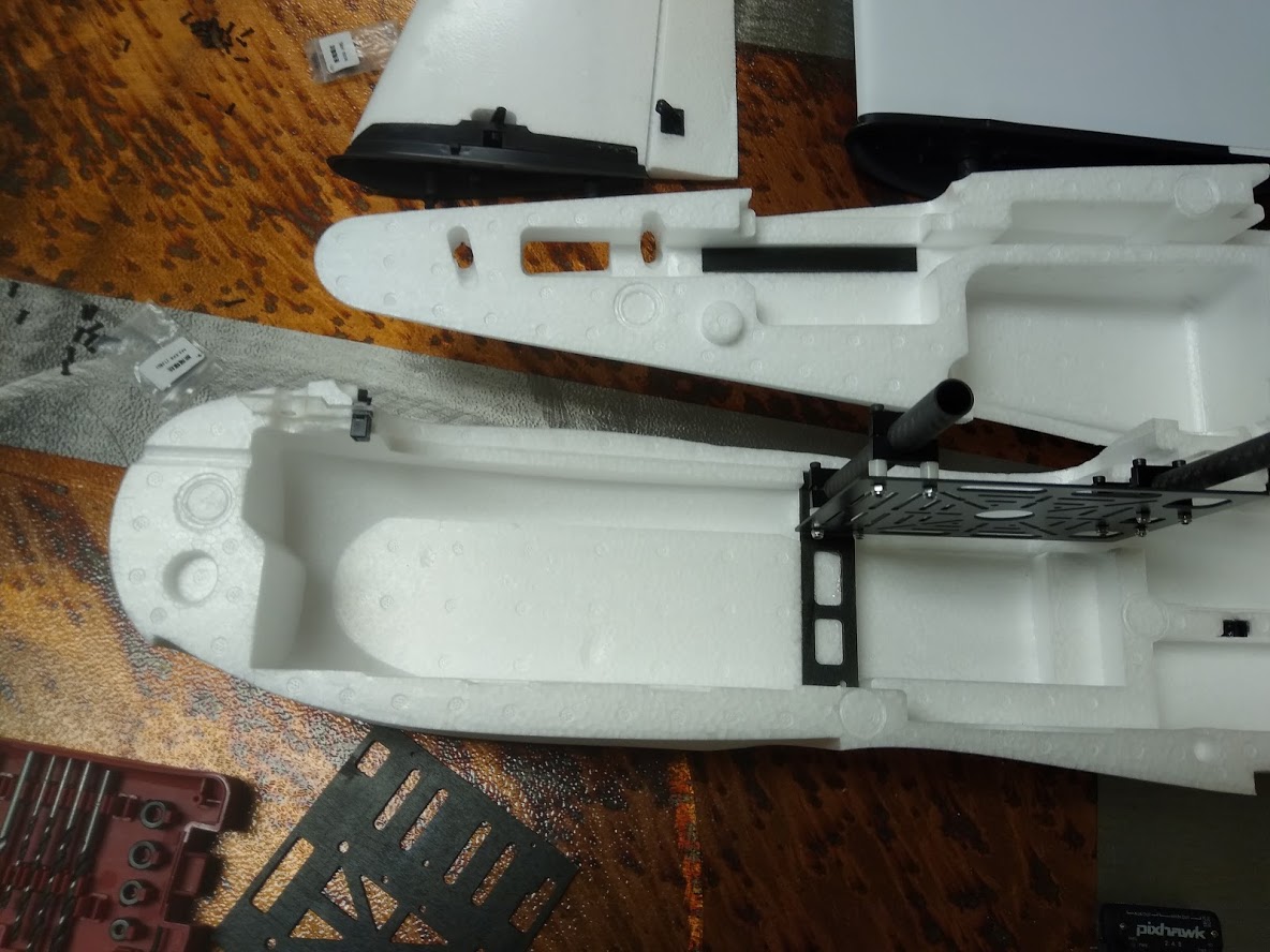
By “rectangular opening in the bottom of the boom”, do you mean the slot in the carbon boom itself? As far as I’m aware, there is no such cover. At least, there never was on my older airframes, I can’t say for certain on these new ones. I haven’t fully unpacked them yet, I only opened the boxes and took a few pictures of the major parts. It’s going to be a bit of time before I start building them, I’m afraid, I’ve got too many other projects to complete first.
Looking back at your pictures, the airframe you received is an interesting assembly indeed. It has the screw type latches as you say, but the center section of the boom (the part glued into the wing) is of the newer type. Older ones had a smaller slot on the bottom.
Wiring harnesses are… not fun, on these. I’m not sure how much I trust those tiny wing-to-fuselage connectors to carry the full current of two motors in hover. On previous planes, I’ve drilled holes in the plastic to allow for adding separate XT60s for the rear motors.
One other thing. You asked about the type of yaw control available, here’s what my experience has been:
Traditional quadcopter yaw (via motor torque) is, well, non-negotiable. It’s going to have it. To be more precise, there’s no parameter to turn that off, and I’m not comfortable (or even sure if it’s possible) setting PID values to 0.
There is a way to do it, but… Unless you feel like compiling your own firmware, you’re out of luck.
Vectored yaw control, on the other hand, can be turned off or on by changing your tilt servo type and setting your servo travels appropriately.