Using "measured" MOT_THST_EXPO: What improvement can one expect?

The expo function works between MOT_SPIN_MIN and MOT_SPIN_MAX. You have used it in your code outside of that range and as I suggested earlier, that is why you are getting silly values.

You asked for the code I was using, you already had my simple code and were not applying it properly so I gave you code that would work out a zero thrust pwm value and max thrust value. If you feed it sensible data it is quite stable.

Depending on how far above the zero thrust prediction you set MOT_SPIN_MIN you get a reduced expo number. Since very few people move their minimum throttle past about 10% thrust this does not impact the average users performance. Advanced users are free to do the measurements and set it up as accurately as they like.

For most people this is good enough and it does not need to be changed. Your measurements support that.

MOT_PWM_MIN and MOT_PWM_MAX do this.

No, the motor mixers do all that.

MOT_SPIN_MAX, MOT_SPIN_MIN, MOT_PWM_MAX, MOT_PWM_MIN do that.

No, the expo curve is fit to the range of MOT_SPIN_MIN to MOT_SPIN_MAX. So if you move MOT_SPIN_MIN you will look at a different range of the thrust curve and get a different MOT_THST_EXPO because we assume zero thrust at MOT_SPIN_MIN.

I could have specified it so MOT_SPIN_MIN and MOT_SPIN_MAX did not require a change to MOT_THST_EXPO but I would have had to include two additional parameters and complicated it for the average user.

I calculate MOT_THST_EXPO based on my fit. It will be fine if I am able to use a low MOT_SPIN_MIN. Some ESC’s have low throttle sync issues and need a higher MOT_SPIN_MIN. If that is the case I adjust MOT_THST_EXPO accordingly.

I set MOT_SPIN_MAX to the PWM range where I no longer see an increase in thrust. Normally the top 5% gets chopped off but that depends on the ESC.

All pretty simple and straightforward.

???

there is somewhere some important piece of information which is not sufficiently communicated. It’s always simple to argue that something isn’t properly applied if that something is improperly documented. So let’s go through it step by step.

The expo function works between MOT_SPIN_MIN and MOT_SPIN_MAX. You have used it in your code outside of that range and as I suggested earlier

pl have a look at this:

From that I would say that your statement is incorrect. I do narrow the data to [SPIN_MIN,SPIN_MAX], following what is shown in the mathlab script. If that ranging is not correct then pl explain how to apply SPIN_MIN/SPIN_MAX to range the data.

that is why you are getting silly values.

the major difference is that you use a totally different function, with a multiplicator a3. I don’t think there can be any question about this here

MOT_PWM_MIN and MOT_PWM_MAX do this

??? even for UAVCAN escs, which have a fixed range of 0…8191 ???
I was assuming that these parameters are relevant only for PWM ESCs, to adapt to the specific ESC
what are these parameters then exactly doing for UAVCAN ESCs?

I continue to claim that your procedure doesn’t make any sense. In order to get myself out of too much guessing I looked up the code.

In the multicopter code I find these three functions of relevance:

  1. float AP_MotorsMulticopter::apply_thrust_curve_and_volt_scaling(float thrust)
  2. void AP_MotorsMulticopter::update_lift_max_from_batt_voltage()
  3. int16_t AP_MotorsMulticopter::calc_thrust_to_pwm(float thrust_in)

The function update_lift_max_from_batt_voltage() is responsible for calculating the factors _batt_voltage_filt and _lift_max, which are used to compensate for the effects of a reducing battery voltage. For the present discussion this effect is irrelevant, and both can be set to 1.0, meaning full battery.

The math done in the other two functions can be summarized as follows, where I have simplified the variable names in an obvious manner, to make the equations better readable:

// converts thrust_in = [0…1] to throttle_ratio = [0…1]
throttle_ratio =
[ -(1.0-expo) + sqrt{ (1.0-expo)*(1.0-expo) + 4.0 * expo * lift_max * thrust_in } ]
/
[ 2.0 * expo * batt_voltage_filt ]

// converts throttle_ratio = [0…1] to X = [spin_min…spin_max]
X = spin_min + (spin_max - spin_min) * throttle_ratio(thrust_in)

// converts X = [0…1] to pwm = [pwm_min…pwm_max]
thrust_to_pwm = pwm_min + (pwm_max - pwm_min) * X

The latter equation is irrelevant to us, since it adapts to the specific ESC pwm range, which for our UAVCAN ESCs should be set to 1000,2000. Thus, we have to look at how the plot of X vs thrust_in looks like.

thrust_in is in the range of [0…1], and by virtue of how throttle_ratio is calculated, also throttle_ratio is in the range of [0…1], where moreover throttle_ratio(0) = 0 and throttle_ratio(1) = 1. So it spans the full range of values from 0 to 1. The second equation limits that to the range [spin_min…spin_max]. Thus we have a function X(thrust_in) which on the x axis goes from 0 to 1, and on the y axis from spin_min to spin_max.

What we need for fitting is the inverse function, thrust_in(X). On the x axis it therefore goes from spin_min to spin_max, and on the y axis it goes from 0 to 1. In between it is a poly, i.e.

thrust_in = (1-expo) * X_norm + expo * X_norm^2

where

X_norm = (X - spin_min) / (spin_max - spin_min)

This leads to exactly ‘my’ procedure of applying spin_min and spin_max, as well as to the fitting function I have used.

In summary, your proposed fitting strategy appears to be arbitrary in the sense that it doesn’t bear any relation to what is calculated in the code.

EDIT: I however, unfortunately, have implemented ‘my’ procedure in the script incorrectly! So, in some sense it is correct to say that I have not applied spin_min/max correctly, since I didn’t do exactly what I intended to do. The effect will be to reduce the value of expo, which is now about 0.75-0.80. However, my statement that the ‘alternative’ fitting procedure doesn’t make any sense, and is incorrect as it doesn’t reflect what the code does, remains valid. In fact, it yielded 0.59, while one should use 0.75-0.80 in order to make the calculations in ArduCopter represent the data. If that difference is considered irrelevant, then the whole concept is irrelevant, and one doesn’t need to bother with data at all.

I note that for this aspect it is irrelevant if the data, which is an estimated thrust curve, is ‘good’ or ‘bad’. The above points are based on one and the same data set.

EDIT 2: I’d like to add: Obviously the value of MOT_THST_EXPO is, for one and the same motor system, very sensitive to the choice of the MOT_SPIN_MIN/MAX parameters. This makes this quantity pretty much useless for characterizing the thrust characteristics, e.g., for comparing different drive systems. It’s a said before, one fits an elephant here. So, a better quantity needs to be found. I think that’s an important result, at least it is to me it, since I actually was kind of believing that MOT_THST_EXPO would be something like a characteristic exponent, which it is not. Thrust curves (thrust cs rpm) are usually described by an algebraic function, i.e., ‘real’ exponents. I guess it would be interesting to see if that approach could give a better characteristic also for the thrust vs pwm curves.

:slight_smile:

Hi Olliw42,

I am happy that you found the problem. It looks like you included your junk measurements at the lower end in the data fit though and that is probably why you are still getting the wrong result. (in the context of a real tune)

It is worth noting that my numbers are based on just the first sweep too as I was doing a quick calculation. If I use all the data and the remove all values below my Min PWM setting I get:
Min PWM : 0
test : Expo : 0.99985 , Zero Throttle : 0.034106 , Max_Thrust : 0.87124
Min PWM : 0.05
test : Expo : 0.99985 , Zero Throttle : 0.034106 , Max_Thrust : 0.87124
Min PWM : 0.1
test : Expo : 0.99985 , Zero Throttle : 0.034106 , Max_Thrust : 0.87124
Min PWM : 0.15
test : Expo : 0.99985 , Zero Throttle : 0.034106 , Max_Thrust : 0.87124
Min PWM : 0.2
test : Expo : 0.72572 , Zero Throttle : 0.14802 , Max_Thrust : 0.86822
Min PWM : 0.25
test : Expo : 0.6265 , Zero Throttle : 0.18258 , Max_Thrust : 0.86504
Min PWM : 0.3
test : Expo : 0.72258 , Zero Throttle : 0.14755 , Max_Thrust : 0.86744
Min PWM : 0.35
test : Expo : 0.87766 , Zero Throttle : 0.083542 , Max_Thrust : 0.86909
Min PWM : 0.4
test : Expo : 0.99973 , Zero Throttle : 0.028075 , Max_Thrust : 0.86911

MOT_THST_EXPO is not intended to be a way to characterise the motor, it is a variable used to linearise the thrust in over the used range, a sensible and simple way. If used properly it does a good job. Like many things it is easy to use incorrectly.

Yes, as we implement it, it was never intended to be a figure of merit to compare drive systems. It’s sole purpose is linearise the thrust characteristics for the purposes of maintaining a good tune over the throttle range.

Looking at your data it appears like your ESC’s are not operating reliably below 0.2. Using only data above 0.2 I get an EXPO of 0.6265. If I adjust the minimum throttle to 0.2 I would need to adjust the expo to 0.54157 if I wanted to make it perfect based on your data.

A final note on the application. The goal of MOT_THST_EXPO is to ensure the gain of the PID loops remain reasonably constant throughout the throttle range. That means it is not the thrust fit that is really important, it is the slope of the thrust fit.

This has been demonstrated to work extremely well in practice. As you can see using your data, you can get reasonable results with a range of parameters, depending on the throttle range your aircraft works in and how tight your tune is. Compared to the majority of pilots, my aircraft cover a significantly greater throttle range and I have much higher expectations of tune quality. As such I go to much greater effort to ensure I get the most out of my aircraft.

For the vast majority of pilots a value of 0.65 combined with a simple autotune will make them very happy.

I have left the “noise” at small pwms in the fit, since it’s not reasonable that the current is zero there. These noisy data have the effect of giving some small current in average in this region and to “bend” up the fit a bit yielding a more realistic result.
Cutting out parts, as you do in somewhat arbitrarily setting min and max is IMHO not appropriate. As you mentioned, explained, demonstrated, and agreed to, the value of EXPO is much dependent on the choice of min/max. Thus, it must be determined in accordance to what min/max values are actually used by ArduPilot. Otherwise it’s an arbitrary number generator, of no use for setting ArduPilot’s EXPO parameter. In fact, I see a bit of a bias in your reasoning, it seems that you kind of like some values better than others and rather prefer to move your min/max around to get there. I argue the other way around.
Glad to hear that you agree that the value of EXPO has no meaning, in the sense of a characteristic value. I totally understand that this is not what is needed here, you just needed some analytical expression, and your choice is perfectly fine. It’s more that I was a bit surprised to realize it’s true nature, since exponents are usually used to characterize the thrust of propellors, and I’m kind of used to think about exponents in terms of a characteristic value. In other words, the MOT_THST_EXPO could be derived from a more fundamental description of the thrust curve which typically would be characterized by a characteristic exponent.
As was concluded already in the above, the large majority of us don’t really need to worry about getting EXPO really perfect, only if it gets extreme one may want to act. But it’s probably good to have a relatively simple method at hand to identify that. And reassuring to know that one is not totally of the mark if one finds it to be normal.
:slight_smile:

cheers, Olli

BTW, I think it would bit a bit of a stretch to claim that the KISS 32A ESCs do not operate reliably below 0.2. I guess you rather would want to discuss that with Felix/Flyduino, not me :smiley: 
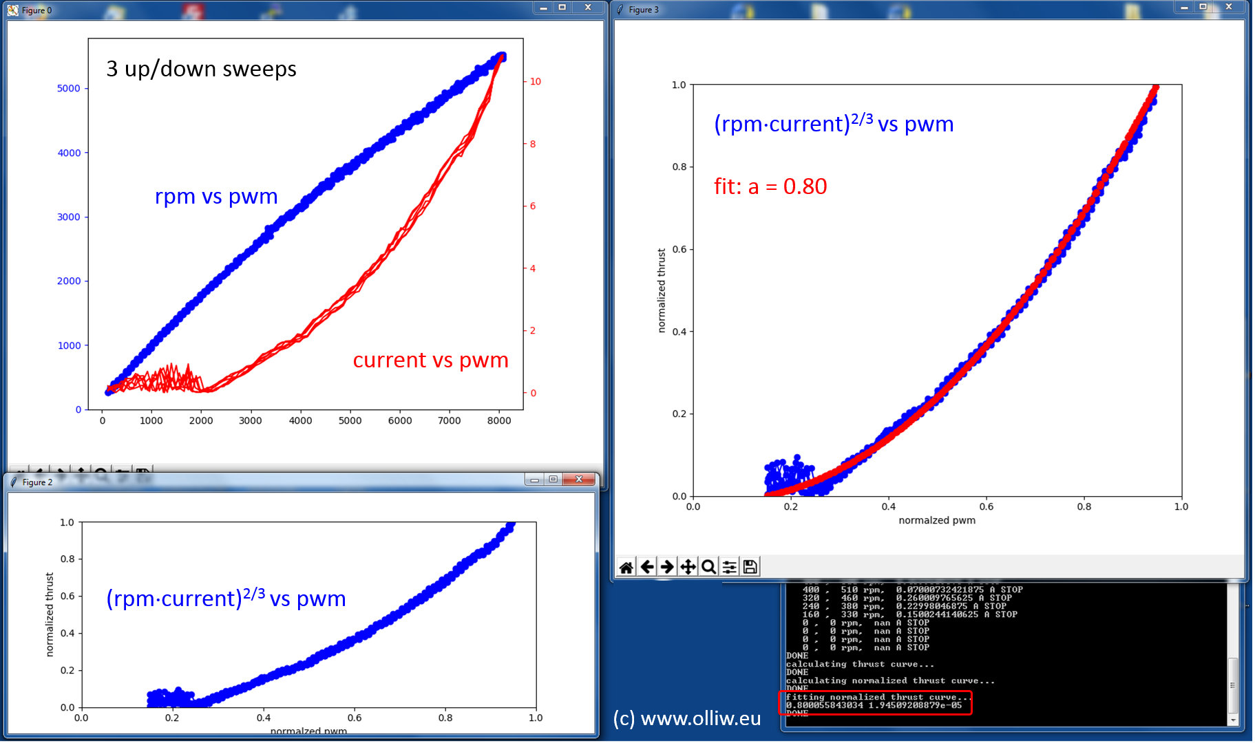
The current measurement however, as I’ve pointed out earlier, indeed doesn’t look reliable here; I’ve brought this already to Felix’s attention.

Obviously bad data does not give a better results. It is either repeatedly going back into restart mode or it is blatantly bad data. In either case you are just adding noise and messing up your fit over the good data.

There is nothing abetary about cutting out the data I chose to cut out. I chose that point assuming the ESC is still going in and out of start mode there. You don’t want the controllers to have to deal with that as it increases the load on the ESC and increases the chances of sync loss.

Given that you are not actually measuring the thrust curve here and I can’t actually tell if the motor is stuttering or if it is a bad current measurement this is just an exercise to demonstrate to other users how to approach the problem.

Statements like this make me wonder if you actually understand why we are doing this at all or if you are simply having fun trying to get a rise out of me. If you don’t understand I am happy to try to explain it to you in simpler terms. (see what I did there)

%%%%
For the benefit of others
-The process is define the minimum thrust level that will result in reliable operation of the esc/motors. To do this you need to get the motor/esc on a thrust stand and do step increases from minimum throttle to mid and max throttle. This defines the MOT_SPIN_MIN. You should also consider your ESC settings to ensure reliable operation during these tests.
-Then plot your thrust curve and check for a flat spot at the top of the ESC throttle range. If you have this set MOT_SPIN_MAX to take it out.
-Finally you set MOT_THST_EXPO to get the best fit of your thrust curve between MOT_SPIN_MIN and MOT_SPIN_MAX. There are some instances where there is an unusual thrust curve that this simple equation does not fit well to, often caused by over powering the prop. In that case you need to consider where in the thrust curve you will be operating generally and consider choosing a curve that does not increase the gain of your pid loops over the throttle point where you do your tuning.

For most people this isn’t necessary unless you are working with a wide range of take off weight, or are building a racing aircraft (think of it as TPA for racers).
%%%

Yeh I called it EXPO because I thought people would relate to it through the EXPO function in their Tx. The equation is based on physical reality of propeller thrust vs voltage drive with some loss. That is why the single value approach works well. Thankfully the same equation can be still used when starting from a non-zero minimum thrust.

Oh, you do like to cause trouble don’t you :slight_smile:

first, I don’t treat anyone just for the sake of it. And, honestly, it’s exactly the other way around. Statements like this make me wonder if you actually understand what you are doing here, and what is wrong with your number gaming and why it is wrong. Also, I think I have explained this now through arguments at least three times. It’s clear that you don’t see the fallacy you are trapping into here, and it is sad that you are not willing to assume for a second that the arguments I presented could have a merit, which they have, and give the arguments a thought. I would recommend looking up the phrase I’ve used twice in the above, but I assume it would not be perceived as a well intentioned recommendation, so I better don’t.

Oh, you do like to cause trouble don’t you

I do have opinions, and I have clearcut arguments leading to these opinions. If you consider this as like to cause troubles, then you’re free to do so, but I really don’t have to worry about or should take serious such an interpretation.

Anyway. the relevant conclusion has been drawn now twice, and the question raised in the title been answered.

good luck
Olli

Hi Olliw42,

Sorry for offending you Olliw. I assumed that you were aware of the condescending way you talked and that you were just playfully trolling a little so I played a little myself.

You came to the thread with some interesting work that may have some value if we can establish that the results are representative of the thrust curves on the problem propeller examples. Thank you for that!

I pointed out a mistake and where you made it. You then spent a bunch of time arguing that you didn’t make the mistake I pointed out or that it was my fault in some way. You finally worked out your initial mistake and corrected it. Thank you for that!

I then corrected you on your interpretation that the value was meant to be more than a single value interpolation factor for measured data over the used range. You continue to make demeaning statements about the usefulness of the approach that would suggest to users that have not taken the time to understand the math that the MOT_THST_EXPO factor is not important or worse does nothing useful at all. That doesn’t help anybody and calls into question if you actually understand the application/purpose or if you just understand the math.

You also directly claim that I am biased towards specific values rather than use a specific engineering approach to the problem at hand. You then ignore that approach when it is described and demonstrated to you. Quite frankly this is blatantly offensive to an engineer.

Yes, your approach has potential but without comparison to measured thrust data, especially problem combinations, we can’t tell.

Finally you suggest that I was:

And you insinuate that I was criticizing

I assumed that the smiley face meant you knew what you were saying was both completly inaccurate and inappropriate it is so I responded in kind under the assumption you were joking around. Unfortunately it appears that you are unaware of how inappropriate you can be in your replies or you apply different standards to others than apply to yourself. I don’t know which and I don’t particularly care.

So I think I can summarise what we agree on:

  • For the purposes at hand MOT_THST_EXPO is a factor used to line fit the thrust curve of the esc/motor/propeller thrust curve.
  • When calculating a line fit it should be done over the data within the range that you are using in practise. As such it is prudent to discard data outside of that range to achieve the best line fit possible.
  • Finally a user doing this should understand how to shift and scale the axis of normalised input vs thrust to ensure the MOT_THST_EXPO is correct when it is applied to in ArduCopter.
1 Like

MOT_THST_EXPO could maybe be autotuned (or post-tuned from log) ? What about measuring performance at different levels by setting throttle demand to a few different levels, then compare power*voltage or vertical acceleration produced at the different levels.

1 Like

According to prop physics correct expo value should be 0.67 (2/3) for static thrust of ideal prop. That is very close match to recommended 0.65 setting!
Variable prop and motor losses, ESC design and other factors make that number differ from theoretical value.

According to prop physics correct expo value should be 0.67 (2/3) for static thrust of ideal prop.

Where did you get 0.67 from?

“Where did you get 0.67 from?”

From aerodynamic control volume approach, for example actuator disc theory. This is example:
https://web.mit.edu/16.unified/www/FALL/thermodynamics/notes/node86.html
See there “11.7.3 Actuator Disk Theory” section. If we take expression for Power (closer to the end of section 11.7.3) , set u0=0 (static thrust), simplify and express Thrust through Power, I think we will get T=const*P^(2/3) for ideal (no loss) system.
If we assume that ESC-motor power is proportional to PWM input, then ideal thrust curve expo is (2/3).
I measured battery side of esc when I did my thrust curve, current draw was proportional to control signal, voltage close to constant. So in that case supply Power = cont * PWM approximately.

Edit: I was wrong: checked my records, current draw was closer to PWM^2

image

This equation? if you set U0 = 0 you get power = inf?

edit: rather I mean you get power = zero but you cant solve for T?

Yes, this equation, but you have to open brackets and simplify it first, before you set U0=0, this way you get rid of U0 in some terms, and then other terms will go to zero with U0=0
Basically only first term with T/(AdiscU0^2pho/2) will stay in play

Wolfram seems to think there is no solution

It can be easily expanded and simplified on piece of paper. But let’s try wolfram at different angle, set ones to zeros, since they get multiplied by U0=0 anyway, like this:
p = 1/2 * U0 * T * [(T/(AU0^2rho/2) + 0)^1/2 +0] solve for T

I can’t figure out how to copy link to solution :slight_smile:

Edit:
I think this is proper wolfram input:
Limit [1/2 * U0 * T * [(T/(A * U0^2 * rho/2) + 1)^1/2 +1], U0->0]

Yeh, this is not correct. It is closer to RPM is proportional to PWM.

What is the status here?
Is there a working script that is verified to produce correct expo value?
If the script were a mavproxy plugin - one could automagically fetch/configure correct parameters needed to run the test.
I had trouble getting Flame80A -driven octaquad to behave well under all conditions, with 0.8 or so expo - and suspect this parameter is a major reason…

Hi guys, I have check the file “ArduPilot Motor Thrust Fit.xlsx” and studied the formula of Normalized Thrust. Does it just depend on the voltage drop over higher PWM pulse (say 21.72V at 1000us and 21.52V at 2000us) or it also vary if we supply higher voltage (6S, 7S…)

I just want to understand the formula (any research or theory behind?) so, could you please verify this @Leonardthall?

Thanks in advance.

Hi, is it possible for you to upload that MATLAB script here. It seems to have been lost and I am not able to find it. Thanks