A number of users have been asking how to setup the MatekL431 CAN adapters for PWM or DShot. This post explains how to set it up and gives a place for users to follow up with questions.
I’ll be concentrating on two scenarios:
- using the adapter to turn DShot capable ESCs into CAN ESCs, including full ESC telemetry
- using the adapters for PWM for servos and other actuators
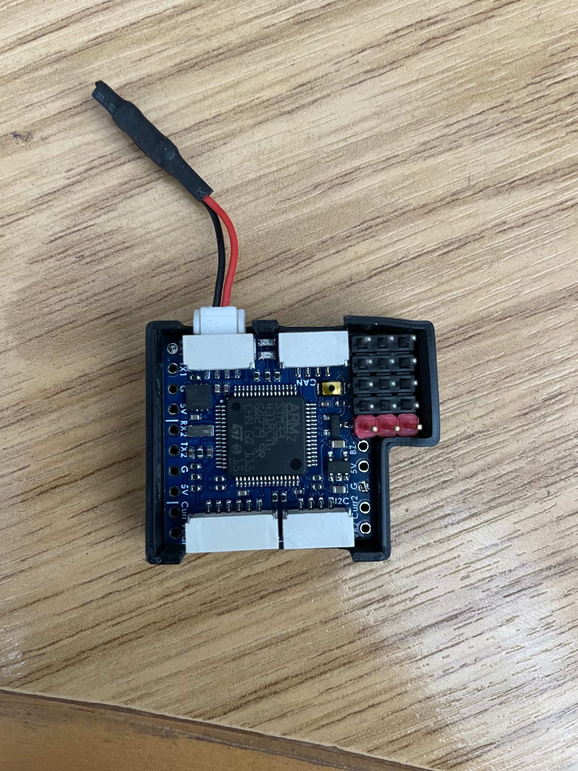
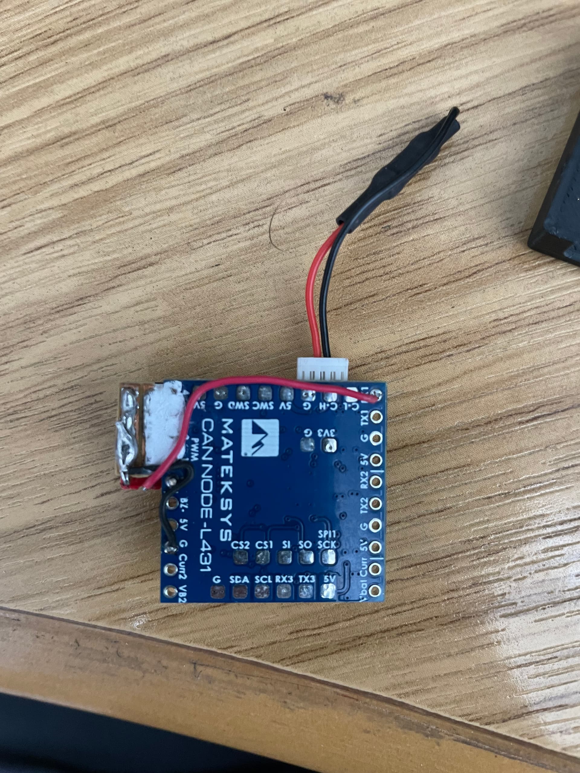
UPDATE: The picture above now shows a new form factor for these adapters
Requirements
You will need to be using ArduPilot 4.2.x or later, and use the MatekL431-DShot firmware. You can get the latest firmware for the node from here:
https://firmware.ardupilot.org/AP_Periph/latest/MatekL431-DShot/
You will also need the DroneCAN GUI tool. If you are using Windows then you can download it from here:
https://firmware.ardupilot.org/Tools/CAN_GUI/
You can also use MissionPlanner to configure the CAN node, but my examples below will be using the DroneCAN GUI Tool.
DShot ESC Adapter
The first example will be using these nodes as a DShot ESC adapter. In the example I will set it up as follows:
- an quadplane using outputs 5 to 8 for 4 ESCs
- DShot capable ESCs, with serial telemetry. This could be BLHeli32 ESCs or APD F series ESCs.
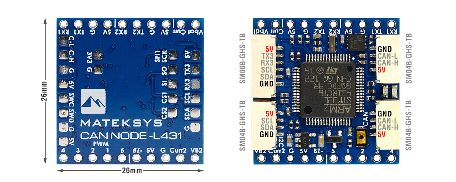
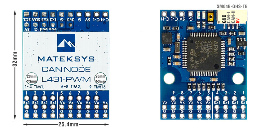
To wire it up you could connect 3 wires from each ESC to the CAN node, the ground, the DShot signal wire and the serial telemetry wire. The ground from each ESC should be connected to a ground “G” pad on the CAN node. The signal wires from the 4 ESCs should be connected to the first 4 PWM pads on the CAN node, marked as “1”, “2”, “3” and “4”.
The serial telemetry pin from all 4 ESCs should be all connected to the same “RX1” uart receive pin.
I will assume you are using the first CAN port on your flight controller. For the above setup you would need to set the following parameters on the flight controller:
- CAN_P1_DRIVER = 1
- CAN_D1_PROTOCOL = 1
- CAN_D1_UC_ESC_BM = 240 (this is 0xf0 in hex, or use the bitmask selector to select your 4 motor outputs)
If you are using Plane 4.2.1beta1 or later then I’d also recommend setting CAN_D1_UC_ESC_OF to 4. This sets an ESC numbering offset on the CAN bus. It makes the transmission of the CAN ESC control packets much more efficient, and also makes the setup of the CAN nodes easier. This parameter was introduced in 4.2.1beta1, it will be in future releases of copter as well, although typically copters number their ESCs starting at SERVO1 so having an offset is less important.
The next step is to install the MatekL431-DShot firmware on the node. Using the DroneCAN GUI tool to connect to your flight controller. Note that recent versions of the GUI tool can connect to MAVLink ports, so you don’t need to setup the CAN_SLCAN parameters if connecting with MAVLink.
Use the Update Firmware button on the node view to install the latest MatekL431-DShot firmware
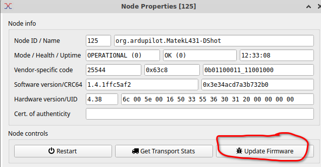
After the firmware is installed you need to setup the CAN node parameters. The default setup with this firmware is provide DShot to CAN ESC conversion for 5 ESCs.
The key parameters to look for are:
- OUTn_FUNCTION which should be set to 33 + ESC number
- OUT_BLH_MASK which is a bitmask of what ESCs are active. For 4 ESCs it should be set to 15 (which is 4 bits set).
If you are using the 4.2.1beta1 or later firmware and have set CAN_D1_UC_ESC_OF to 4 then you should set OUT1_FUNCTION to 33, OUT2_FUNCTION to 34, OUT3_FUNCTION to 35 and OUT4_FUNCTION to 36.
If you haven’t set the ESC_OF to offset the numbering then you would set them to 37, 38, 39 and 40.
The reason for this numbering is 33 is recognised as “first ESC”, so it says that this output should look for the first entry in ESC RawCommand DroneCAN packets.
After setting up the parameters reboot the node and then use the motor test function to test your ESCs. Note that you will need to ensure the safety is off.
To diagnose, you should use the Bus Monitor under the tools menu in the GUI tool to look at the packets.
Here is what you would see in the bus monitor for a 30% motor test on the first ESC:
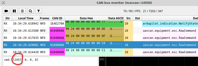
The value 2457 depends on your motor expo settings, the key is seeing non-zero values and the cmd array length matching the number of ESCs.
The way that ESC commands are encoded on the bus is why we added the CAN_Dn_UC_ESC_OF parameter. If you are using outputs 5 to 8 on a quadplane and you didn’t use the offset of 4 then it would encode the outputs for the above motor test as:
cmd = [0, 0, 0, 0, 2457, 0, 0, 0]
this will take 3 CAN frames, whereas with the offset it is 1 CAN frame. So using the offset reduces the required CAN bus bandwidth by a factor of 3x.
ESC Telemetry
When setup correctly the CAN node will see ESC telemetry from the ESCs and will route this back to the flight controller as esc Status packets, like this:

you can see it gives voltage, current, temperature and rpm for each ESC.
These will appear on the GCS as ESC_TELEMETRY_nn_to_mm MAVLink packets and in the onboard logs as ESC log messages.
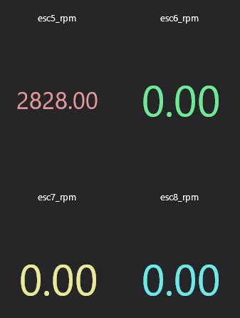
In MissionPlanner you can display these in graphs or the Quick panel. For example, here is the RPM for 4 ESCs on a quadplane (which uses outputs 5 to out for VTOL motors) during a motor test with the first motor running
Setting up for PWM Outputs
As the default parameters for the MatekL431-DShot firmware is setup for DShot ESCs you need to do a bit more work to output PWM for servos.
On the flight controller you need to set:
- CAN_D1_UC_SRV_BM to a bitmask of the servos you want to send over CAN. For example, if you wanted to send your first 4 channels you would set this to 15.
- CAN_D1_UC_SRV_RT to the output rate. The default is 50Hz, which is good for most servos.
On the CAN node you need to set a few things: - set OUT_BLH_MASK to 0 to disable the use of DShot
- set ESC_PWM_TYPE to 0 for normal PWM
- set OUTn_FUNCTION to 50 + servo number for each output you want enabled as a PWM output.
- set OUTn_FUNCTION to 0 for any outputs you don’t have connected. Do not leave them at the default of 33 + ESC number
For example, if you had an elevator servo on SERVO2 on the flight controller and you want this to appear on the first output of the CAN node (on the pin marked “1”) then you would set OUT1_FUNCTION=52 (that is 50 + the servo number on the flight controller). If you wanted a rudder that is on SERVO4 to appear on output 4 then you would set OUT4_FUNCTION=54
I also recommend setting OUTn_MIN to 1000, OUTn_MAX to 2000 and OUTn_TRIM to 1500. That will allow you to use the SERVOn_MIN, SERVOn_MAX and SERVOn_TRIM values on the flight controller to control the outputs range and center in the usual way. It is possible to use other values on the node, but it gets more complicated to understand the mapping of the PWM values, so using 1000, 1500, 2000 is recommended (it will mean the PWM
value in your flight controller logs matches what is sent by the node).
As with the ESC setup it can be helpful to look with the DroneCAN GUI tool bus monitor to see what is happening.
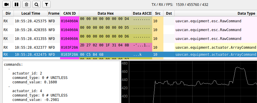
The above shows the actuator ArrayCommand that is used for servos. In this case it is sending 2 servo outputs, one for output 2 and the other for output 4 (eg. elevator and rudder). The value is from -1 to 1, so a value of 0.0 means set the PWM to OUTn_TRIM. A value of 1 means set to OUTn_MAX and a value of -1 means to set to OUTn_MIN.
Mixing ESCs and Servos
It is possible to setup the node to send a combination of ESCs and servos, but there are some rules you need to follow.
The first 4 outputs on the node are all on the same timer. This means all 4 must either be ESC outputs or servo outputs. You can’t mix ESCs and servos on the same timer. So you could have 4 ESCs and one servo, or 4 servos and 1 ESC.
We will likely expand the firmware of the MatekL431-DShot to allow for up to 8 outputs using other pins in the future. If we do that I’ll follow up with some more information here or in the wiki.
UPDATE: @Sampson reported this not working with a MatekH743 boards, and when we investigated we found it didn’t work as the board doesn’t have a safety pin. The safety state was never getting set to “armed” and communicated to the CAN node. I have opened a PR to fix this: ChibiOS: add BRD_SAFETYENABLE on all boards by tridge · Pull Request #20812 · ArduPilot/ardupilot · GitHub and plan to include it in plane 4.2.1.
Meanwhile, a workaround is to use the control-F “toggle safety” option twice on MissionPlanner. The double toggle changes the state to “safety armed” and works around the issue. Not a nice workaround I know, but until the bug is fixed it is the best I have.