When removing the extension cable and measuring directly from the ESC, there is only a voltage of 1V.
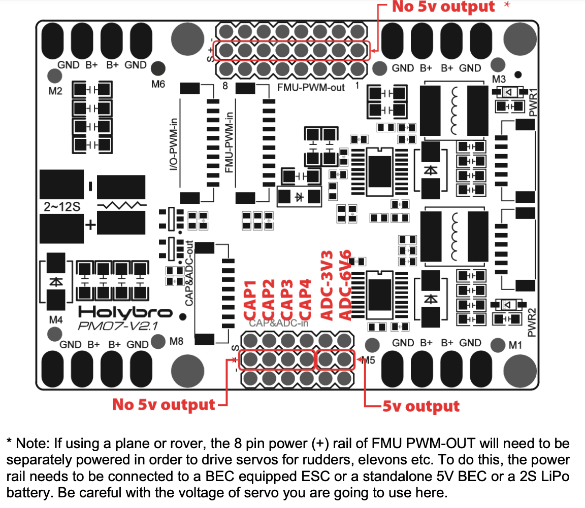
Looking at the PM07 board plan (http://www.holybro.com/manual/PM07-Quick-Start-Guide.pdf), we can see that there are two 5V outputs. However, when we measure the voltage on all the different pins, we do not receive a 5V voltage anywhere.
The FMU-PWM-out (top of graphic) only gives us a maximum of 1V if the Eneloop pack is disconnected. On the CAP&ADC-in we get 0V.
As far as we are concerned, everything only works with the Eneloop pack connected.
Do not try to get 5V for the servo from anywhere on the Pixhawk or PM07. Servos can demand quite a lot of power and you might damage the PM07 or the Pixhawk. If there is only 1V between the red and black wires coming from the ESC, the BEC might be damaged. This can happen, if you backfeed power through the ESCs servo connector. The eneloop pack will have done just that. To avoid any risk, take a sharp knife and lift the plastic tab holding the red wire in the ESCs servo connector and pull the wire out. Take shrink tube or insulating tape to protect against short circuits. To get rid off the eneloop pack, you could buy a standalone BEC and solder it to one of the ESC solder points on the PM07.
So this is what we can see in the quick start guide for the PM07 board. There it is written, that you need a separate power source when using a rover.
Currently, I am not quite sure if I have understood your description right.
The servo has three cables: Black (ground), red (+) and white (PWM signal). Should we now solder the white cable to the PM07 board and power the red cable through a separate source? And where exactly is the BEC? Is it part of the board or is it an external compound we can take out? I’m a beginner with electronics, so I’m very unsure about this.
If you were so kind, could you phrase it in a way so that I can understand it more clearly, please? If you have any resources (like manuals or soldering plans), those would also help me a lot.
Ok, if you do not understand what I am talking about, please tell me and I will try to explain it better.
Please do nothing to the servo, leave it as it is.
The BEC is a device like a transformator just for DC voltage instead of AC. It can be part of the ESC (the device that controls the motor) or a standalone device. It takes the higher voltage of a power source (lipo) and converts it to a lower voltage. Usually 5V or 6V for components like the RC receiver or servos.
Integrating a powerful BEC into the autopilot or PM07 makes no sense, because there will always be someone, who does not need it (multicopters) or needs a bigger one.
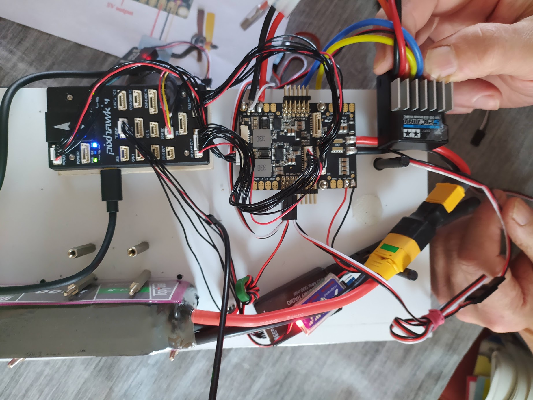
As I said, from what I can tell from the pictures, there should be nothing fundamentaly wrong with the rover.
How can I find out if the one in the ESC is broken? Do I have to measure the voltage or is there any other way I could find out if the internal BEC is broken?
For the back feed power that comes through the ESC’s servo connector, should I include a protective diode in the wiring?
Thank you already in advance for your answer!
Edit: Among the countless things the previous person gave me along with the rover, there is a Holybro PM02 v30 power module included. Furthermore, there is also a Hobbywing UBEC 3A-6S 5v/6V.
As I wrote in a previous post, you have to meassure the voltage on the white/red/black cable coming out of the ESC. There should be 5V between red and black on this cable. You have to connect the lipo to the rover for that.
If there is no voltage or 1V as you wrote earlier, it is broken.
In that case the Hobbywing UBEC would be the part you need to replace the internal BEC.
Please remember to pull the red wire from the ESCs connector. Even if the BEC is damaged, it may still overheat or cause other problems, if it is powered from the wrong side.
We have soldered the UBEC to the Holybro board – it’s working great, we finally have a voltage of 5.2V.
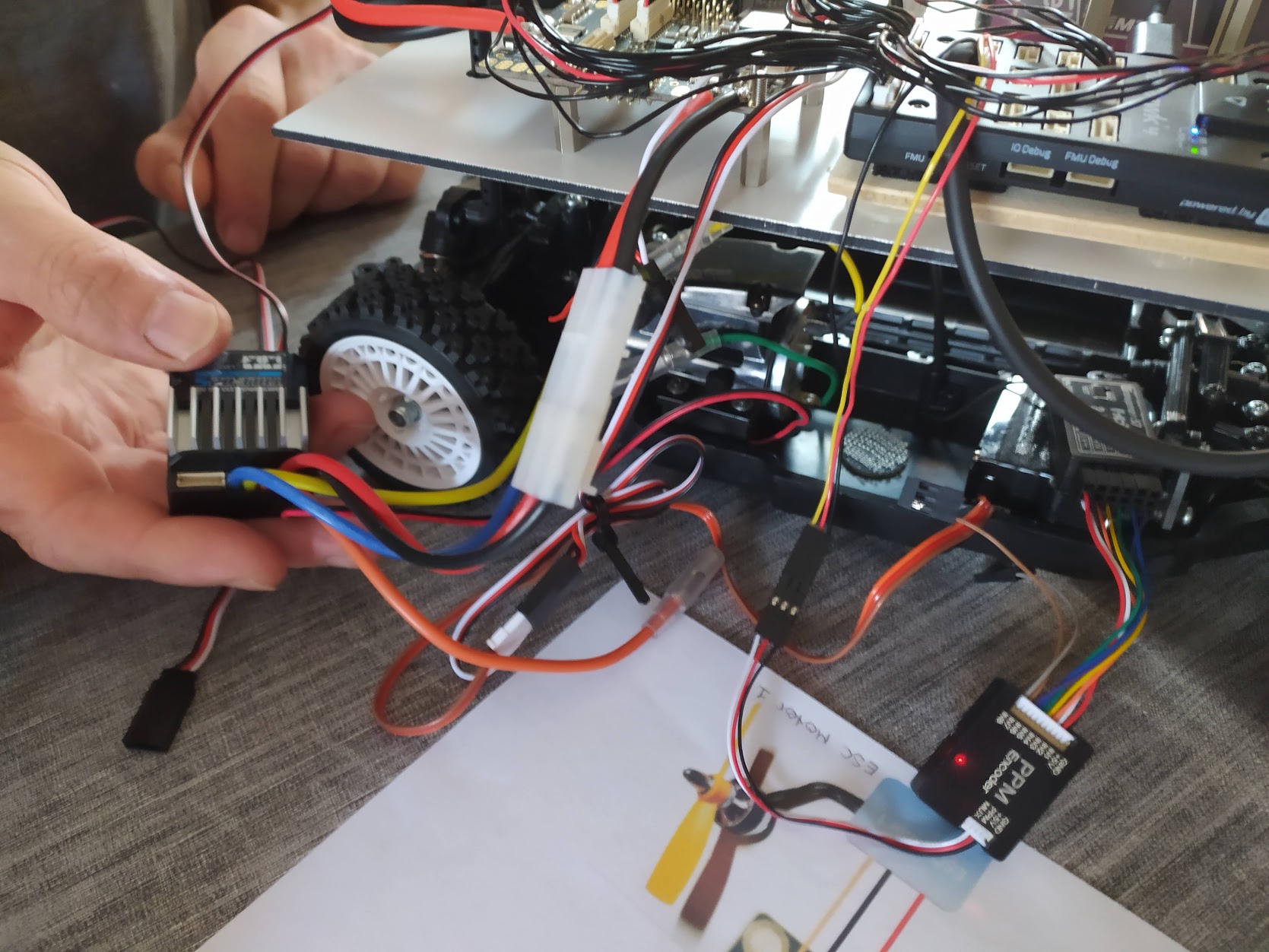
The servo for the steering and the ESC for the motor work. However, if we removed the red cable from the ESC, the motor suddenly does not work and the red LED on the ESC is blinking. If we use the red cable, then the red light on the ESC turns off and the motor is running.
Since we only measured 1V coming from the ESC yesterday, could it be that the ESC is damaged or that we actually need to use all three cables?
FMU PWM out Nr. 1 = Servo
FMU PWM out Nr. 2 = UBEC (5V)
FMU PWM out Nr. 3 = ESC
A standard RC ESC requiring 5V from an external source is unusual. There are opto-ESCs, which do not have an integrated BEC for external components (no red wire in the 3 pin connector), but they have a small 5V or 3.3V BEC circuit for their own electronics.
I guess your ESC uses the same BEC circuit for external and internal 5V supply. If the BEC is broken, the ESC electronics will need 5V from an external source to work. This is not an ideal situation and I would replace this ESC. It is not as dangerous as with a plane or a multicopter, since there are no fast spinning props or the rover will fall from the sky if the ESC fails, but the ESC might reboot during operation and lead to unpredictable behaviour.
Spoke to my supervisor. He will order a new ESC, as I have asked him to. He thinks the current ESC can still be used until it breaks down but I’m against it personally. Using the damaged ESC any further could cause damage to other elements, couldn’t it?
Nobody can say what a damaged part might do. The biggest risk with electricity is always a short circuit and fire. I would not risk anything for the few euro a new ESC costs.
@count74 When using an external cable with the red cable removed, the ESC will blink in red and green alternating. That means that the motor cannot be used due to a connection error.
If we plug in the ESC directly to the Holybro board with the red cable active, the motor works. So we need the red cable to make things work.
That is strange, but if it only works that way… Does the ESC output 5V through the red cable?
One thing to check is the polarity of the extension cable. Make sure it is plugged in signal to signal, ground to ground.