I am using the latest version of QGC and ArduPilot with a TT-02 Chassis by Tamiya and a Graupner HOTT MX-16 RC.
Even after setting all the motors up and switching the safety switch, the motors are still not being found. There is one motor with brush, and it’s bound to channel 3 of the RC. Could it be, that there is a problem with the wiring? As, when I try to test the motors, the first four (A to D) react by switching from armed to disarmed quickly.
Does anyone have any experience with a similar problem? If anyone is in possession of a wiring plan, could you please send me a link to it or a PDF, if you have one?
You speak of “all the motors”, but as far as I know, the tt-02 has one motor and one steering servo. You also do not mention which hardware you are using. I hope it is no APM 2.8…
If your hardware is running ardurover 4.0, the basic setup requires you to select the function of two servo outputs. One should be “throttle” and the other “ground steering”. You are free to select any output you like (the wiki still recommends 1 and 3). You then have to connect the servo and ESC signal cable (3pin) to the corresponding ports on the servo rail.
Please read https://ardupilot.org/rover/ to get a working rover and feel free to post any further questions.
Hi, thank you for your answer. I am unfortunately not the person who set the vehicle up, and the person who did has not given me any manuals that came with any of the parts, so I’m searching for everything right now.
Yes, it has one motor (mapped to channel 3) and one servo (mapped to channel 2).
The hardware is not APM 2.8, but a Holybro PMO7-V22.
Where exactly in QGroundControl would I set up the servo? I cannot see a specific mapping option anywhere.
I also have an AHRS issue in the pre-flight checklist, which it tells me to check for in the console, but I find no message relating to this.
Thank you for helping me; I’m an absolute beginner when it comes to these things, especially since I was only meant to program software in the beginning and then was told to do the hardware as well.
The Holybro PM07 is a power distribution board. It is meant to be used with a Holybro Pixhawk 4 or other flightcontrol boards.
Have a look here to identify which flightcontroller is installed:
The parameter names for the servos all start with servoX, where X is the number of the output.
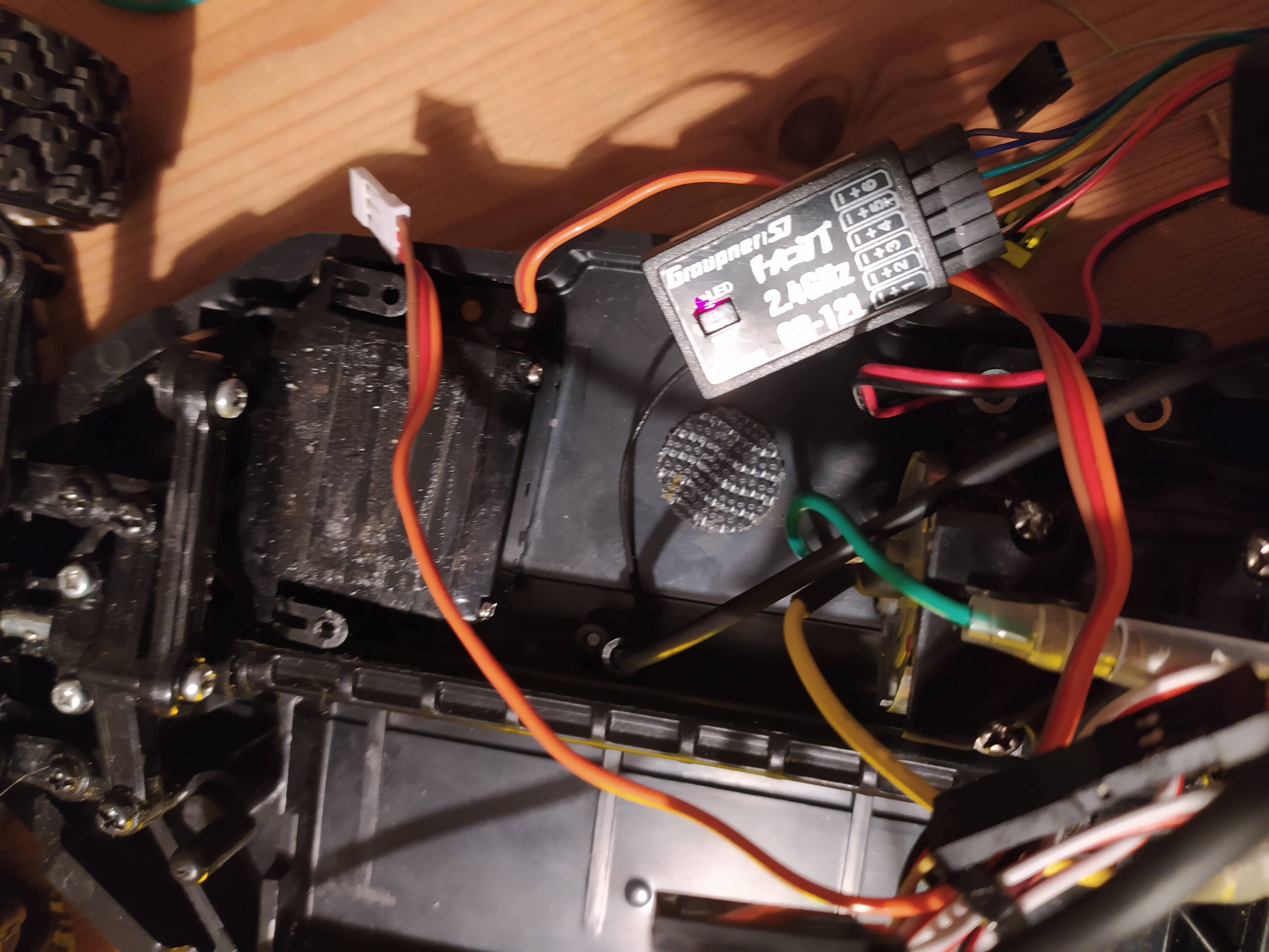
The hardware should not be to complicated to figure out. If everything is preconnected, I would first take detailed pictures of everthing. This way you can build your own documentation. You can also use those pictures to ask questions here.
Do not worry about the AHRS error now. First try to get the rover to drive at all.
The flight-control board is a Holybro Pixhawk 4, sorry for not specifying that earlier.
We’re currently reading through manuals for all hardware compounds to see if all the wiring is correct (since I was not the person who set the vehicle up) and to check the motor connections.
I will take some pictures and post them here later.
I had a brief look at the photos.
Five things I noticed:
Try to put the lipo down into the chassis to improve stability. Such a huge mass high above the wheels will make the rover prone to roll over when turning.
To improve EMC, try to twist all the cables carefully. Especially the thin wires connecting the Pixhawk to the peripherals. This also makes it less likely to rip/cut/pull an individual wire. Just disconnect one end of the cable and turn it round and round, till the wires are twisted around each other. Not to hard, of course.
Where do all the wires from the GR12L receiver go? If they are not connected to anything, you should remove them. Only one 3 wire cable should be needed. It looks like yellow/red/black goes to the PPM port of the Pixhawk4. Is there a PPM encoder between the receiver and the Pixhawk? If so, then you can remove it and connect port 6 of the receiver to the PPM input of the Pixhawk4. The GR12L needs to be set to SUM0 (analogue combined signal on one wire, usually called PPM) mode via the telemetry menu (old info, perhaps that has changed) of the transmitter. It should also be possible to use a digital combined signal called SUMD. To use it, you need to connect port 6 of the receiver to the DSM/SBUS port of the Pixhawk4 and configure the receiver via the transmitter. All manuals for the transmitter and receiver should be available for download from Graupner.
The GPS module should be the highest point of the rover, with free line of sight in all directions.
It might also help to put a thin sheet of metal under it (10cm diameter), to act as a groundplane. I sometimes use jar lids for that.
What are the eneloops doing there? The power module should provide all voltages needed to operate the rover.
Unfortunately, I was not the person who set the vehicle up. I am supposed to define research specific functions for the autopilot, and someone else was taking care of the vehicle setup (wiring etc.) in the meantime. I don’t have any notes from them either, so I honestly have no idea why they wired things the way they did, as I’m not familar with building and setting up vehicles myself.
Is there a simple wiring of the Pixhawk 4, the motor, the servo, and the Holybro PM07-V22 to test the basic functionality with? Looking at the wiring we also came to the conclusion that there are some mistakes, and now we would like to figure out whether it’s just the wiring that’s wrong or if there is also a problem with the Pixhawk itself. Essentially, we want to test the connections between Holybro PM07-V22, the servo, and the motor.
Thank you already in advance for your answer! You’re helping me a lot!
It is difficult to make any real mistakes during hardware setup. The cable set that came with the Pixhawk 4 should cover most connection needs and each cable can only be connected to a specific port. You can not plug a 4 pin connector into a 6 pin port.
The servo wires have the V+ in the middle, so even if you turn them around, nothing bad happens, it just will not work.
The solder points are the only place where bad things might happen, if the polarity is reversed somewhere.
I had a closer look at the photos and found one thing that may keep the rover from working.
The Pixhawk 4 has two PWM output ports, IO PWM (Main) and FMU PWM (Aux). Those two ports are connected to the corresponding ports on the PM07. That means, the two servo connectors on PM07 port 2 and 3 are not connected to Servo 2 and 3, but Servo 10 and 11. There is also a signal cable soldered to connection point M1 which would be Servo 1. Depending on the servo output configuration in ardurover, the ESC and steering servo will never get a PWM signal. A screenshot of Missionplanners servo config screen would help. Or a parameter file.
My solution would be two switch the IO and FMU PWM cables, so Pixhawk 4 IO PWM out is connected to PM07 FMU PWM in. This connects the 8 PM07 servo ports to the first 8 ardurover servo outputs. The cable soldered to M1 would not be needed anymore.
Other than that, the configuration should already be the minimum needed for a working rover.
I’m going to check those connections out later, as the LiPo is currently being charged. We had a premonition that the previous user made some connection errors.
I will try to fetch a parameter file or screenshot for you from the QGroundControl software (I’m not using MissionPlanner as it’s usable on Microsoft Windows only and for my project it’s best if the GCS is cross-platform usable).
Thank you for your help! I will get back to you as soon as possible (when the LiPo is charged).
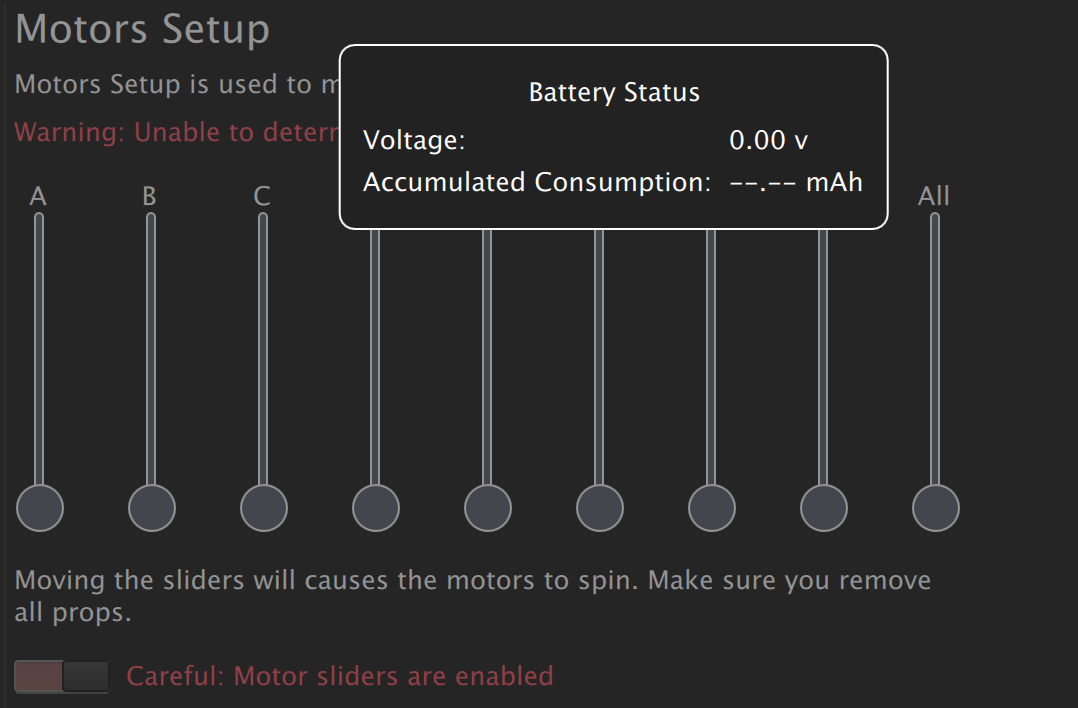
We switched the IO and FMU PWM cables. In the motor setup, motor A now activates the motor of the vehicle. B, C, and D cause the Pixhawk to produce noise but do not move any elements. The motors E to H do not cause any reactions.
As seen in the screenshot above, the battery gives a voltage of 0.0V to the vehicle. Now we are trying to figure out if the servo works at all. When we directly send voltage to the servo, without changing the connections to the vehicle and hardware at all, nothing happens. Currently, we assume that the servo might have been broken in the efforts of the last person who tried to make it work.
I will upload some pictures of the servo and its connections later.
To test single components, you need to eliminate other sources of error. You should connect the servo directly to the GR12L receiver to test it. If the eneloop pack is charged, you can connect it to any other port of the receiver to power it and the servo. Even it is not fully charged it should be good for a short test.
Try all the sticks on the TX and different receiver ports and see if the servo moves.
Also, the Pixhawk 4 does not provide power to the servo connectors. Make sure the red wire coming from the ESC is actually connected to the servorail. The ESC should have a BEC build in, to provide power to servos (and the receiver in a non-autopilot rc car).
The battery showing zero Volts does just mean the battery monitor is not configured correctly or at all.
We have narrowed down the error sources to either the servo itself or to the wiring of the server to the PM07. Tomorrow we will check these things in detail, as there is voltage running in the elements on top of the car (such as the PM07, the Pixhawk 4, and the other modules) but there is none going to the servo.
We also assume that on the PM07, the wiring of the servo might have been in the wrong place. The motor connector comes after the servo, and while the motor works, the servo doesn’t do anything. Meanwhile, as I have written in an earlier reply, the motor channels B to E do cause a reaction (no movement but producing a sound). This could mean that the pin the servo is currently connected to is probably not being recognized or something else.
@count74 I just wanted to let you know that I finally got the motor and the servo to run. We put the servo on pin 3 (previously on 2), the motor on pin 1 (previously on 3), and the battery pack can go on either pin 2 or 4 to work (previously on 1).
In QGroundControl, under “Motor Setup”, slider A controls the servo, and slider B controls the motor.
I am currently unsure as to why the pins have to be in this order to work. I assume that the previous user either wired something wrong or that the Holybro PCB has a wiring error.
Do you have an idea of what could be wrong?
Thank you already in advance for your answer! I wouldn’t have managed to get the motor and servo to work if it hadn’t been for your continuous help and input. Thank you for that!
There is probably nothing wrong with anything. With ardurover 4.0 the user is free to select any available function for any servo output. So if the servo was connected to pin 2 and the ESC to pin 3 and it is not working, you just have to check the configuration for SERVO2_function and SERVO3_function and if they are set to “groundsteering” and “throttle”.
The “battery pack” is the eneloop pack? It should not be necessery for operation of the rover. The ESC should provide power to the servo rail/servo through the red wire in the servo plug. It may actually damage the ESC to feed power to it through this connector from the battery pack. If you have a multimeter at hand, try and meassure the voltage between the red and black pins in the ESC 3pin connector.
And the battery pack should power the servo rail no matter to which of the 8 ports it is connected. All the V+ pins are connected together and so are the Ground pins, only the signal pins go to individual pins in the “FMU PWM in” connector.
Ok, but still, it should not be needed. The ESC controlling the motor gets its power from the lipo battery, it should not need another power source. If the ESC has a servo connector with white(or yellow)/red/black wires, it should have a BEC built in, which takes the lipo voltage (3 lipo cells, around 12V in this case) and converts it to 5V (sometimes 6V) to power other RC electronics. The eneloop pack is just an additional point of failure/maintenance and NiMH packs take forever to charge.
So either the ESC has no BEC, which would be strange for an entry level RC car, the BEC is damaged or the red wire is not connected through to the PM07 servo rail. Are there any extension cables used?
Measuring the voltage that goes from the FMU-PWM-OUT on the PM07 to the servo, there is just roughly 1V (black and red wire) instead of 5V. As soon as we connect the eneloop pack to the PM07 board as well, we get 6V. Without the battery pack, we literally do not have enough voltage to power the servo.
Unfortunately, I do not know what the previous user (who was supposed to set the vehicle up) did to the PM07 board, so there might have already been damage done to it.
Do you have an idea, what could be done to fix this error?
There is no error regarding the PM07 or the Pixhawk 4. They do not provide power to the servo rail.
This is the reason why it only works with the eneloop pack for now.
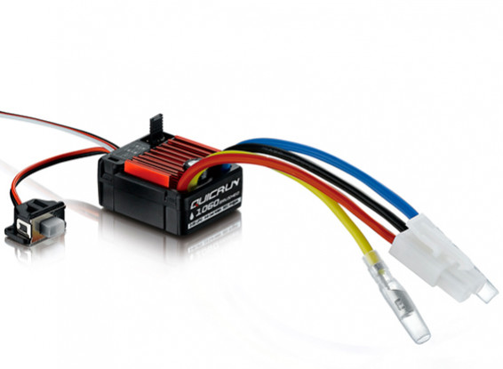
What you should do, is meassure the voltage on the ESC/motor servo connector, when the lipo is plugged in. Below is a picture of an ESC for brushed DC motors. It should be similar to the ESC in your rover. The big black/red wires are soldered/connected to the PM07, the blue/yellow wires are connected to the motor and the white/red/black cable leaving the picture is connected to the PM07 servo rail pin 1 (according to your information). Please meassure the voltage between the red and black wire in this cable, coming directly from the ESC, no extension cables and the ESC switched on if it has a switch.