Hey guys need a little help understanding the filter better.
According to the wiki
Set INS_HNTCH_REF = hover_thrust to set the harmonic notch reference value
So the first line says to set the ref to the hover thrust…so mine was .211 so it was set as INS_HNTCH_REF,0.211
Then it says
Set INS_HNTCH_FREQ = hover_freq to set the harmonic notch reference frequency
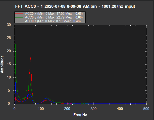
So I set INS_HNTCH_FREQ,132 which is middle of the noise spike I beleive.
Then is says
Set INS_HNTCH_BW = hover_freq / 2 to set the harmonic notch bandwidth
Which I take to mean 132/2 =66 but I was told to set the BW value to INS_HNTCH_BW,25
Today I still see some noise, now I confess it’s much better then it was…but is this bandwidth value incorrect.
I ask because I still see some noise around 61hz and wonder if the bandwidth is off or if the reference frequency is off.
Now after today I did a tune and noticed that the INS_HNTCH_REF,0.211 should now be INS_HNTCH_REF,0.1818076
But not sure if that will make a difference.
Sorry for the questions but just trying to get my head around it so I stop bothering Andy.
Is there a step by step documentation on how to set up the filters. The wiki is good but it leaves more questions then answers. It shows an example of a 5 inch quad, ok but what was learned from the graphs and what would the settings be that come from that. Just looking to learn.
I wrote the wiki page @rickyg32 - always happy to make it better - please feel free to suggest some additional text once we have got you past this.
Setting the BW to 61 is fine I think - these are guidelines, so there is no right answer. You basically want as narrow a notch as you can get away with but half of your noise peak frequency is a good place to start.
BUT you are trying to nail the first harmonic - i.e. the frequency at which your motors are actually spinning. So based on the size of your quad I am going to guess that this is 61Hz rather than 132Hz you should therefore set INS_HNTCH_FREQ to 61 and INS_HNTCH_BW to 30. The biggest peak is not necessarily the motor frequency - and on larger copters its quite often the second harmonic, i.e. double the motor frequency
Thank you Andy and please don’t think for a second the wiki isn’t a good piece of work. It’s awesome. But I struggle to understand this sort of thing. However with a document that runs one through an example and explains why the settings are done as they are. IT makes it easier for thick people like me to learn lol.
When I read the wiki’s I seem to constantly walk away asking…but why.
Here is what I think I am being told to do.
Basically start with turning on whats needed to log the noise.
Then look at the noise on teh graph and find out what the peek value is…That should be the reference frequency…in my mind. Then set the bandwidth to cover noise that falls on either side of that peak.
So in my case I see noise at 61 hz…now I confess thats after the filters had already been set.
That said…for conversation sake, if the center of the noise is 61 hz and the noise runs as high as say 76hz and as low as 55hz, then setting the bandwidth to 30 would cover 15h hz in either direction.
Did I get this right.
Also I set the INS_HNTCH_REF,0.211 to hover thrust but I don’t know why. I assume it has something to do with how it knows when to be used…but I am guessing.
Lastly based on your input I could slide the center frequency down to 61 and check the log again to see if that removes it or makes it worse…then adjust as required…
But this is all on back of me thinking I have a noise problem
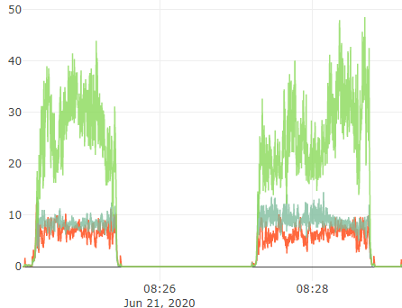
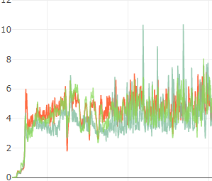
This is my vibration graph a week ago
This is now.
Its vastly different.
I only started questioning it becuase of the bad pitch tune in my other post.
The notch filter acts like an axe head. Think of what your noise peak would look like if you took an axe to it straight down the middle - the very center would be completely obliterated, but the sides would have wedge shaped chunk taken out of them. The notch bandwidth specifies the width of the wedge but as you can visualize I am sure it doesn’t take out all of the noise. However, the notch filter also tracks the middle over time so that you don’t get a large spread out peak.
That’s a measure of accelerometer noise which is not the same as gyro noise which is what the notch filter attacks. However reducing your gyro noise generally affects your accelerometer vibes as well because you are not putting so much noise into the motors.
The way you should be measuring noise is pre- and post- filter FFTs. Pre-filter will tell you where the noise is and post-filter will tell you how well you are doing.
Ah ok so I was close…good. I understand what your saying. Axe…that makes real easy sense for me. lol
So teh filter is Gyro noise…got it. big difference.
So I must be seeing post filter noise when looking at the FFT data now.
So now I am wondering if I even have a problem to worry about as this is vastly different then before the filter was set.
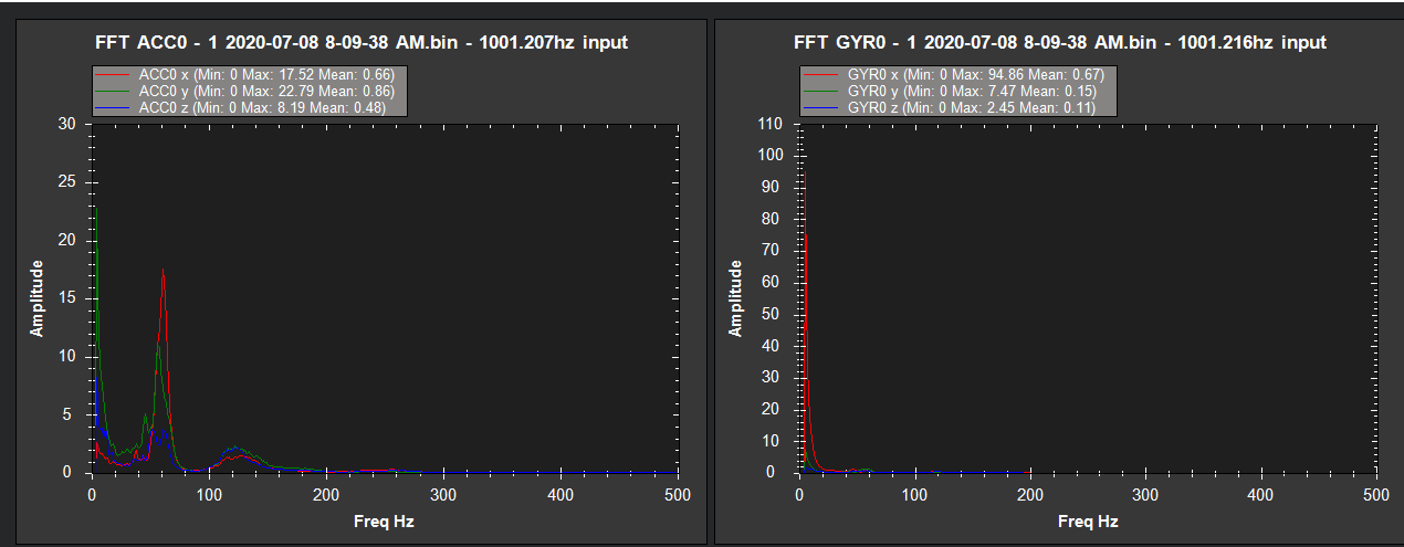
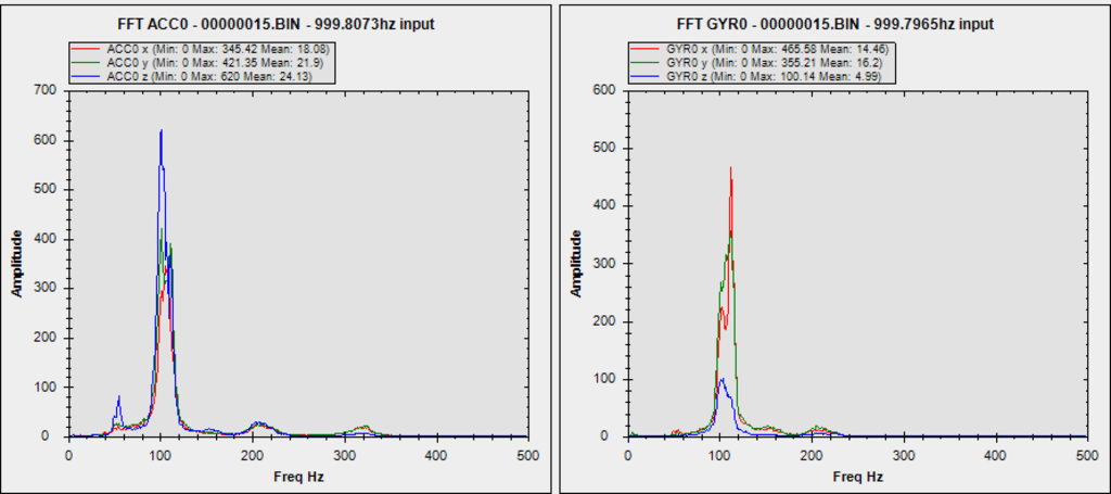
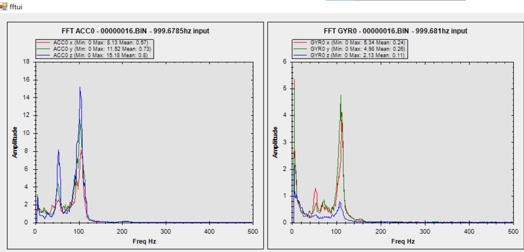
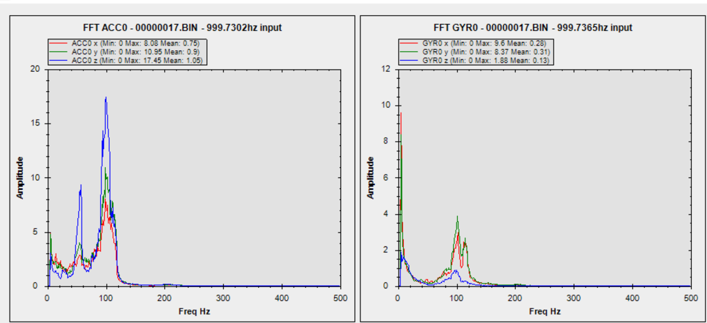
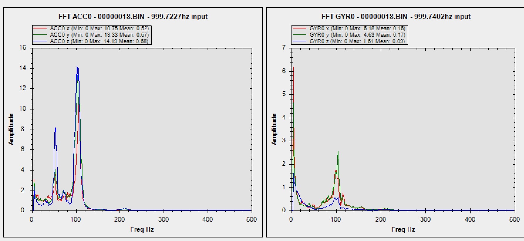
Followed the document on my T960 and come up with the following results. From reading this thread, I think my next step is another post-notch autotune? FFT graphs below.
Before
Looks good. I suspect you get could get the second peak by perhaps broadening the notch a little and playing with the frequency. You can see where the notch is active with the axe shape wedge. So 52Hz maybe?
 - please feel free to suggest some additional text once we have got you past this.