I still see issues in your SERVO definitions and motor placements. According to your .param file, you have the setup below which does not match your diagram. For example, SERVO13_FUNCTION is set to 76 for Right Tilt but is on the left motor. This will affect yaw control. The SERVO11_FUNCTION is set to 34 which is for Motor2 but your diagram says Motor 4…and so on.
The drift turn could be a compass issue or the EKF is settling. Check the “Messages” tab in Mission Planner to see if you get an EKF YAW message. Sometimes, you need to let the plane sit a few minutes to gather satellites or move it forward on the ground to the take-off location.
My guess on your compass issue is that your have an incorrect setting (like ROTATION_NONE) for Compass 1. Have you checked the HUD to verify North, South, East, and West positions? Since your compass is near the same level as your motors, you could try a simple test to elevate it on a (4" to 6") post. If you can post an image of the compass, I can try to determine the correct orientation. The assumption here is that your Pixhawk arrow points forward.
The message below could be from the motor interference or it could be from testing indoors? I would also check the “Obtain declination automatically box” as it pulls it from a 3D GPS fix.
no testing indoors… only outside. I’ll post this week a log file, but i had few probleme with logs. First i had a bad logging error, i format the sd card and now i don’t have a error, but after the flight i connect the pixhawk via usb cable and it’s say no log … why ?
Logging should be automatic unless it can’t write to the flash card. You should get an error if the flash card is not writable. Try disarming before disconnecting the battery. Also, make sure that LOG_BITMASK is set to 65535.
Greg Covey,
I think the problem that I’m having right now stems more from electrical problems but I also see your point and will go back and review my params. I fixed my solder job and only ran the ESC with one motor w/o the prop and it’s still beeps at me after about 20 seconds. When I disarm it and arm it again to run the motors I only get about 2 seconds in before they are beeping at me again. This leads me to believe that the elevated temperature raises the impedance and causes the shutoff. I just realized that my ESC, which is BLHeli_32 compatible, does not have the built in hardware to give me a telemetry readout of the current and voltage as I had previously thought. Prior to buying it I was under the impression that there was no extra cables necessary for this but I guess I was wrong. Definitely one of those face palm moments. Alas… I was actually considering purchasing a Mauch power module to give me access to the current and voltage readouts. Would the Mauch module still work if . I might still be able to use the 4 in 1 that I am currently using if I can get an idea of what the voltage/current is. As it stands, I have my 2 5S batteries hooked up in parallel to my 50A x 4 ESC, giving me an incoming voltage of 40 V. I noticed the hottest part of the ESC is where the battery connects into it. First I will try it with one battery and see if I can run the motor any longer. If that doesn’t work, I’ll also try adding a heat sink/air flow over the ESC to see if maybe its just a cooling issue. I’ll get back to you soon with what it is. Thanks again for all the help!
The ESCs may be beeping because the SERVOx output value isn’t going low enough to initialize it. Have you done calibrations on them? Also, you can manually tweak each one of the SERVOx_MIN values until the ESC becomes initialized. APM Plane has a nice ESC Calibration procedure here. I use Q_ESC_CAL=2 and set it by powering the Pixhawk with a USB cable. You can then use your normal battery power-up to arm the ESCs with the transmitter throttle stick high.
You can use a Mauch PM with anything since it uses a hall effect sensor…no resistance in series.
Hey Greg,
I updated my picture in the last post with the correct motor/servo mapping as well as the newest param file. I was also wondering if you might tell be able to tell me whether or not I chose the right FRAME_TYPE as 0. I did this because the motor placement for the quad + seems more similar to my build than the quad x. The only caveat here is that the quad + motors 1 and 2 are spinning the same direction. This wouldn’t seem to work, however when I tested out the motors they actually spun opposite of what it shows in the diagram I have posted. By the way, I figured out the reason they would beep at me was because I had accidentally bought a series connector instead of a parallel connector. Thank goodness I didn’t blow the ESC. Thanks Greg!
I’m pretty sure that you want Q_FRAME_TYPE set to 1. This keeps your motor output functions to:
33: motor1
34: motor2
36: motor4
The front motor rotation directions don’t matter as long as they are opposite. Also, the rear motor direction doesn’t matter either.
You then want to set Q_TILT_MASK to 11 for motors 4, 2, and 1. I think that SERVO7_FUNCTION should then be set to 41, but I have never had the rear motor tilt.
First of all, I would like to say that this is a great community, seeing so many people that is willing to help others.
Now with my issues: Me and my friends are trying to build a QuadPlane Tilt-Rotor with all rotors tilting.We were able to tilt the rotors when the plane is switched from MANUAL or FBWA to QSTABILIZE. We have everyting set but we have one major issue:
When in MANUAL mode everything is looking good. I can see from the “Servo Output” tab, the throttle I’m giving and Pixhawk responds accordingly. BUT when we switch to “QSTABILIZE” mode we can’t see any output to throttle or any output for that matter whatsoever. And from what I understand in QSTABILIZE mode the VTOL should act like a Quadcopter, which means the control surfaces should not move , BUT they do for some reason; only the rudder remains stationary.
I have set the ARMING_REQUIRE to 0 in order to arm the vehicle since not all the calibration is done. I’ve checked the wiring again and again which seems fine. Radio calibration is alson working fine. Since I can not give any output to the motors I can’t do the ESC calibration with Q_ESC_CAL =1.
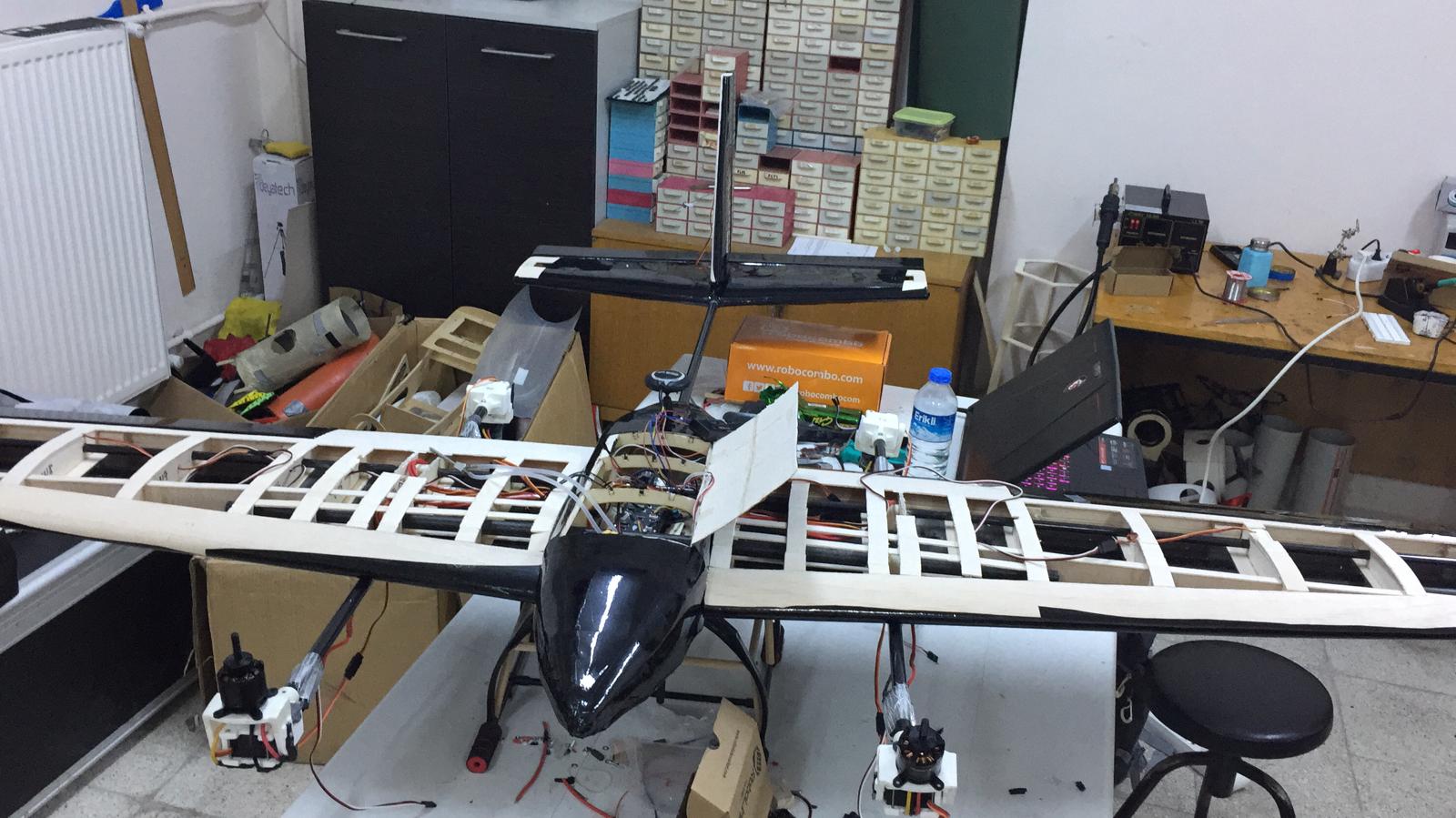
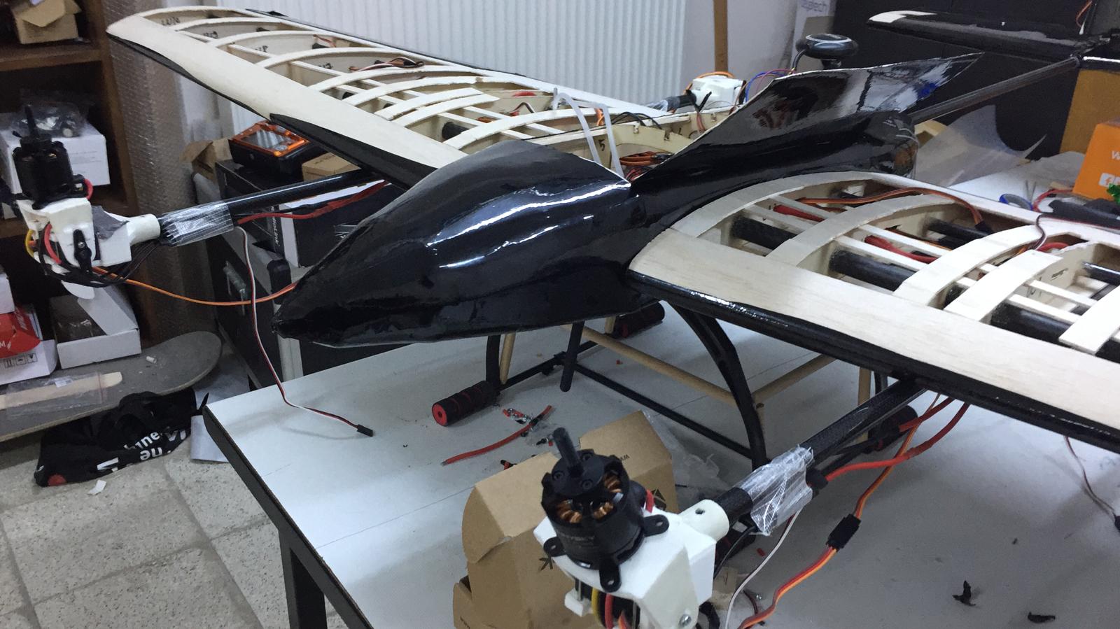
I really hope you guys can help out. I am including some attachments below with a picture of the VTOL.
I am working on a tilt rotor quadplane driven by a petrol engine. The angle of the blades are adjustable by servos. I want to use the quad motor outputs to control the servos. The layout is “PLUS”, the 2 side rotors are tiltable.
I set the parameters below and I would have some questions about it.
I checked the outputs in the status window of the Mission planner. What I recognised, the PWM limits for the servos were not used for SERVO5-8. Only the Q_M_PWM_MAX/MIN limits the output. Is it correct?
The SERVO9-10 stay 0. No output at all. However the SERVO5-8 started to change a lot, when I rotated the PH around the vertical axle. So it looks, it uses the normal quad method to do the yaw control. What can be wrong?
Can I use Chibios for tiltrotor?
I am not certain that APM Plane supports a setup with all 4 rotors tilting. It was under consideration but I have not kept up with the changes to verify that it was implemented. If not, you will need to fix the two rear rotors and use the MotorTilt=41 for the SERVOn_FUNCTION that controls it. Also, the front rotors use the following SERVOn_FUNCTIONs:
TiltMotorLeft=75
TiltMotorRight=76
For the front tilt rotors, you need to set the Q_TILT_TYPE parameter to 2 for vectored yaw control. Otherwise, your plane will spin when hovering. The frame looks very nice!
According to your .param file, the motor ESCs should be plugged into Servo Outputs 6, 7, 8, and 9.
I think APM Plane supports the quad-rotor setup with all 4 rotors tilting since it is mentioned in the tilt-rotor web-page under the quadplane support. I solved my problem. As it turns out the “ARMING REQUIRE=0” parameter is bugged for some reason and I had to use “RUDDER_ARMING” instead to arm the vehicle. More on that here : Arming Require.
The problem we are facing now is that the VTOL only lifts off about 1.5 to 2 meters before starting to lose altitued slowly. Now this is our first ever plane. I will list our setup and talk about possible reasons why it won’t lift off.
Motors : SunnySky X2814 900 kV motors ( 1500 grams lift at 24.2 Amps with 13x6.5 props)
Propellers : 13X5.5 props
ESC’s : 40A Hobbywing Skywalker ESC’s (3s)
Battery : 6250 mAh 3S Li-Po
Total Weight : 4.5 kg
Wing Span : 1.5 meters
Possible reasons for the problem :
-Maybe the weight is too much for the battery. In QSTABILIZE mode while hovering at 1m battery only lasts about 1:30 minutes. We are currently trying to decrease weight and find a more powerful battery or even connecting severeal batteries in parallel.
Maybe there is some parameter I missed that limits the max throttle, though I highly doubt it.
Using 4S ESC’s with 4s batteries might increase efficiency.
You guys here are a lot more experienced than us maybe you guys could guide us to the root of the problem.
Glad you got it working! Can you post the .BIN file from your hover test? Also, what is the C rating on your 6250mAh pack? I suspect that you may need to increase your cell count and decrease the prop size as you are drawing over 100amps.
It looks like you are testing at a University. Be careful when your helpers are so close to the spinning props. Typically, we test with the plane on the ground and a distance away from it.
Can you help me to understand the working of the tilt rotor with yaw control? I set parameters, but it does not work according to my expectation.
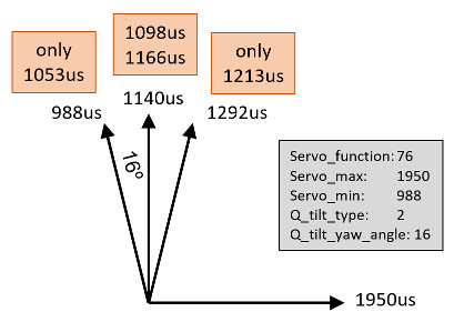
I have made a small drawing for easy understanding. The grey box shows the parameters, what I have set.
When I move the rudder to side totally, the output does not reach the max. allowed number on both side.
Another strange thing is, when I move back the rudder to the center, the output is different according to the direction from I move back, however the input channel shows the same number.
The Servo_max. 1950 works well in Manual mode.
I am just hoping if somenone can help me with the auto mode tuning of a 4 motor tilt rotor (only front motors tilt).
We have successful tuned the plane in quad modes and also in FBWA mode. But in auto modes the pitch behavior is bad. It oscillates in altitude pitching up and down (sometimes very aggressively). It is not able to keep the altitude.
We have tried adjusting the TECS controller with no luck. In the logs the desired and actual pitch angles are not matching at all.
I finally got to maiden my re-designed FireFLY3 VTOL which was created from a crashed FireFLY6 and parts from other planes. To my amazement and joy, it worked quite well! I used Plane v3.9.8 and a Turnigy Talon Tricopter Servo Mount Set from HK for yaw control. I upgraded it with Boca Bearings as shown above in post #27. Fun stuff!
I changed the PTCH2SRV_P value from 1.8 to 1.4 and the elevon pitch flutter disappeared.
It will be interesting to see if I can carry a typical payload of my GoPro H3 camera with Feiyu Tech gimbal or S100 mapping camera. The ascending hover value without payload looks to be around 1670 on the RCOUT PWM C3 and 1450 in FBWA mode for a speed around 16m/s.
I had a chance to grab a guy at the field for a video of my FireFLY3 VTOL so I took it. The conditions were not optimal with a crosswind coming from the camera and pilot’s back. Even though I had a new video guy with a new camera and a crosswind, I was happy with both the hover and flying characteristics of the FF3. A week before, in calmer conditions, it really flew nice. Maybe next time, I can put on my zoom lens.