Throttle reverse (gear)

Also, check the RC3_TRIM. My problem was that RC3_TRIM was 982 by default. Tune it up to 1500 and everything is OK.

Hi I’m facing a similar issue- not able to move the rover in reverse direction.
ESC: hobbywing platinum V4 130A HV.
Servo1 : Function- ThrottleLeft,min-1066,trim-1500,max-1860
Servo3 : Function -ThrottleRight,Min-1066,Trim-1500,Max-1860
I have ticked the reverse[ ] checkbox it toggled my throttle (when its ticked the motor rotates forward when throttle is on the down position).
Is there is any way to test the ESC supporting reverse mode or not ?
or should I set any other prams to make it possible ?.
or any work-around to make it possible to rotate in both direction ?

This is a fixed wing/helicopter ESC. Those ESCs usually do not support bidirectional operation and a quick look in the user manual confirms this. You can set the rotation direction with the programming box, but not bidirectional mode. What kind of rover do you want to power with a 130A non sensored ESC?

1 Like

Hi @count74 ,
Thank you for the confirmation.
I have 2 PMS Motor of 48V, and 13S lipo battery, I would like to make use of it to build a autonomous rover(skid steer).Could you suggest any better ESC for this?

The Hobbywing EZRUN MAX4 ESC is rated to 12S and plenty of current capacity. Anything higher than 12S you will have to get creative I think.

1 Like

VESCs by Benjamin Vedder are also available in a wide variety of voltage and current ratings. The VESC 75 (V)/300(A) should match your battery. The smaller models are rated for 12S and voltage spikes not higher than 60V. The 75/300 know costs around 480€.

1 Like

Thank-you guys @dkemxr , @count74 :hugs:
I really appreciate the effort!
I will check on these options!

Hi @count74 ,
I’m planning to go forward with your suggestion VESC
Or flipsky( based on vesc)

As I’m new to VESC, i would like to get some insights from you regarding connections and initial setups,
can I use the PPM connection of VESC to Pixhwak as i used to connect normal PWM based ESC ?
or should I use UART or other communication methods instead?
If you have any other suggestions from your experience to a new VESC user please post.

Thank you in advance :smiling_face:

Great find! I also use Flipsky VESCs on my rover, but there is some discussion if they actually pay Benjamin something for using his design, so I thought I post a link to the “original”.
The VESC software is a little bit overwhelming at first, but once you get the hang of it, it is easy. The most important thing is to remember is that, even if you are connected to the ESC, all settings are done “offline” and need to be written to the ESC. It is also a good practise to do a read after writing the settings to verify.
I use PPM as an input signal, because even so Ardupilot and VESC support UAVCAN, I never got them to work together. I also seem to remember, CAN in Ardupilot does not support bidirectional operation yet.
The VESC software features an autosetup for the motor parameters. You select the weight/size of your motor, input voltage and the type of sensor/no sensor. Then the VESC software uses some safe base values and starts to energize the motor. This will cause the motor to make some scary noises and rotate in different directions and after that you can test the motor and change the rotation direction. Do not forget to write the settings! Then you need to configure the input you want to use. Be aware that, if you choose multiple inputs, keyboard and PPM for example, they might interfere.
The VESC software also lets you see the input PPM/PWM signal the VESC receives. This makes calibration really easy. It has been a while since I last had to do it, so I will need to refresh my memory once I am at home again. There is a sequence of settings to prevent the motor to spin during calibration and I do not trust my memory enough to write down now.

2 Likes

Hi @count74
thank you for the insights, I will try to get a “original” VESC 75V 300A .
and will update here on my progress…

What you buy is entirely your decission. My information may also be obsolete and Flipsky is now paying Benjamin.

1 Like

I’m looking into this version of FLIPSKY ESC now…

It seems to be more cost effective and high current version.
Do you able to get reverse(& skid-steer)working in your rover(from throttle) by connecting to PPM port of FLIPSKY ESC?

here in the blow blog they have mentioned like “PPM control mode - without positive and reverse switching” any idea what it means?

Thanks in advance :dizzy:

You can configure VESCs for bidirectional operation with PPM. What the PPM signal controls can also be configured. You can use Duty Cycle, Current, RPM, Position (Servo) mode.
I use Duty Cycle on my rovers (10kg and 25kg), but with large and heavy vehicles Current control mode might be more suitable.
In the blog you linked they use a waterjet and you would not want to turn the impeller backwards. The thrust bearing on those things only really works in one direction and running them in the wrong direction might damage the waterjet. They also disabled the brake function and perhaps the drag brake (I did not read it all), so the waterjet just spools down without putting active resistance at the passing water.

1 Like

I have successfully tested my rover with flipsky 75200 ESC,(reverse is working perfectly !! thank-you!)
Parameters
Motor type : medium in-runner (750g)
Battery : BATTERY_TYPE_LIION_3_0__4_2(as I’m using Li-po)
Cell: 12 (i have 13s but to be safe i kept 12)
I have 6 wires coming from the motor,blue,green,red,black ,yellow and white
I guess its hall sensor(i don’t have data-sheet or any details of this motor)
So i have connected
Black-GND
Red-5V
white - TEMP
Yellow-Hall1
Green-Hall2
Blue-Hall3
(This connection made based on general color code on motor sensors)
I would like to find out the exact wires by trial and error( keep gnd and 5v and check all other sensors)
How can I verify my sensor connection from VESC software?

You do not need to sort out the sensor wires. The VESC does that for you during motor setup.
If your motor runs smooth and starts without cocking while under load, everything is fine.

1 Like

Great info above - many thanks. I have been using a pair of flipsky 75100’s in our 250kg rover mower and they have been excellent. I’ve used the “PPM” aka PWM connections from the FC to the ESC’s and no drama. I have read ive greated a potential ground loop, but again no drama so far.

A new pair of 75100’s just arrived for a new project, so im looking to connect via CANBUS, as chaining the ESC’s wil resolve the potential groundloop issue.

Anyone got canbus working with these ? I may need to update the ESC firmware from v5.2 (per doco) to something more recent to fix eRPM and maybe reverse issue. Any pointers appreciated.

I use these for my deck motors on my mowers and I control them (forward only) with CAN. Pixhawk 6C + Ardurover. Fixed my groundloop issues! Given that yours are from the same shop, I suspect yours will work.

For my traction motors I use these 1x VESC 6/75 - £250 each and I also control them with CAN, including reverse.

Incidentally I also have a waveshare CAN hat on my raspberry Pi companion computer to permit the companion computer to receive the status messages those controllers publish.

1 Like

Thanks for your answer Chris - perfect timing.
I put 2x new 75100 VESC’s onto our newer bigger (sadly slower) mower, configured them up (sensorless) using PPM and got some poor behaviour. Not sure why but the skid steer mower would circle instead of track straight sometimes. Wiring, or motor config, groundloop - i dont think so, even though i have 2 ground paths via the two ppms-controller-motor pairs but all at low 28v max. Anyways - to save debuggng pwm / groundloop im diving into Vesc uavcan ↔ ardupilot dronecan configuration.

Finding Vesc - Ardupilot documentation is a little challenging, however

  1. Connecting 2 pin Vesc Can connector pins CAN-H and CAN-L to my Zealot’s 4 pin can hub ports
    (noting 30+ volts across the can-l and can-h pins into the FC - could end badly … )
  2. Setting mission planner CAN_P1_DRIVER 1 and CAN_D1_DRIVER 1 CAN_P1_BITRATE 500000
  3. setting VESC to UAVCAN protocol - scan canbus shows no traffic :frowning: none in devtools either
  4. Mission Planner DroneCan inspector now shows bus traffic - Node 47, so i added CAN_D1_NODE 47
  5. In mission planner after a bit of mucking about - now getting CAN data (joy)

Thats enough for tonight / this morning.

Next challenge(s)

  • getting throttle commands to move the motor on the VESC. and reverse.
  • getting RPM data displayed in Mission Planner

Cheers

1 Like

Update : Seems it was all working - i just didnt have the safety switch available, my disabling hw savefty’s wasnt good enough. Once i connected the safety switch, i now have full ESC control for skid steer

  • esc1_voltage
  • esc1_current
  • esc1_temperature
  • esc1_rpm - which only reads in the forwards direction. Reverse rpms are always 0. No biggie.
  • Forwards and Reverse control

I’ve wired up a Y cable for the canbus - tomorrow i’ll map up the 2nd VESC over canbus, then mow baby mow.

1 Like

and for the sake of documentation -
Ardurover is now 100% for skidsteer with 2x Flipsky 75100 Vesc’s. Forwards/Reverse and turning.
canbus with Y Cable linking 2x VESC to “CAN splitter board” and into the CAN port of th Zealot FC
notes

  • update VESC firmware. i used 6.02 75100_100_v2 - easy and quick drama free firmware
  • always ensure Filters are turned off in the FOC tab - magic smoke problems elsewise
  • set canbus speeds to match - 500K baud eveyrwhere for me
  • set Vesc protocol to UAVCAN - there is no dronecan.
  • set Vesc can ID to the servo/motor channel to use as ESC i used ID 0 and ID 1
    Update: Dont use can Id 0 : telemetry worked initally then stopped - changed to ID 1 and ID2
  • set Vesc ESC index to the ESCn numbers in ardupilot i used 0 and 1
  • i set the VESC canbus throttle mode to “Duty Cycle” - it seemed to work well

Im away from the mower - so Mission Planner can_ parameters from memory

  • CAN_P1_PROTOCOL 1 (dronecan)
  • CAN_P1_DRIVER 1 (driver 1 assigned to port 1)
  • CAN_D1_UC_NODE bitmask - selecting 0 and 1 as ESC’s
    Update: Dont use Id 0 : telemetry worked initally then stopped - changed to ID 1 and ID2
  • CAN_D1_UC_ESC_BM bitmask 0 and 1 from memory
  • CAN_D1_UC_ESC_RM bitmask 0 and 1
  • SERVO1_FUNCTION to 73 (Throttle Left)
  • SERVO2_FUNCTION to 74 (Throttle Right)

hints and observations.
I couldnt find much doco around - but setting the canbus ID to 0 and 1 made servo channels 1 and 2 start to work. I spent a bit of time trying how to map ESC1 to Vesc node 47, but thats not how it works.
Update : As above Dont use Can Id 0 as the telemetry stopped working on it for me. I moved to ID 1 and ID 2 and now both telemetry and control work fine.
SLCAN ate and flooded my telemetry bandwidth. Setting it from 1 to 0 restored things.

Definately have your rover off the ground. I had an uncommanded full throttle. On a 300kg mower it would have been a problem if it was on the ground. This is how i found the Vesc’s ESC index is 0 based.

Mission Planner info is good.


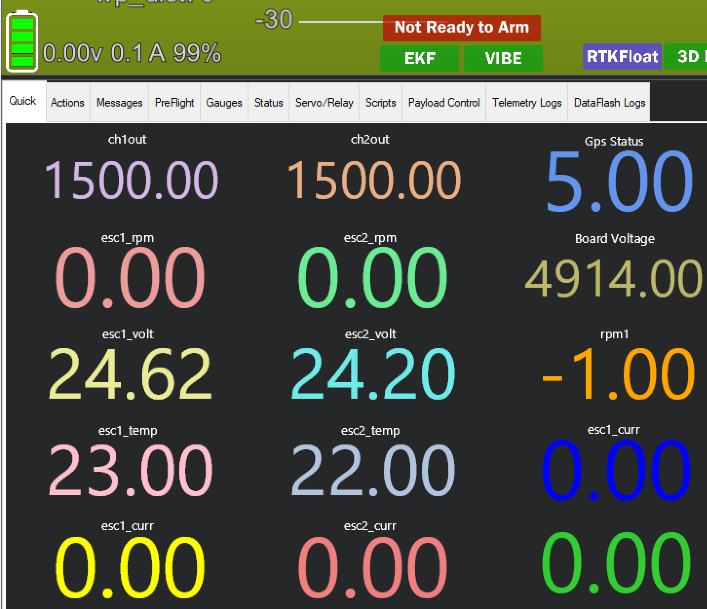
zero RPM is correct for ch1out 1500 - mid throttle.
I had odd behaviour with servo (pwm) range extended 950-2050 with 1500 midpoint. Direction of track reversed at full throttle. >2000 . Reset to standard 1000-2000 and all good.

Cheers

2 Likes