Congratulations on your successful maiden flight! I usually don’t hear talk of AUTO mode on a maiden test flight so you gave it a full workout.
I don’t use MANUAL mode on a VTOL since the fallback modes are for hovering like QLOITER. I may have missed it but what are you using for a battery pack?
I used two CNHL 8000ma 6s 30C Lipos. I’ve had problems w/this brand swelling up but they’ve been OK if I only charge them at 6A - so far. (they where a $130 for 2).
With the voltage dropping so much during transition, I’ll hold off on the Lion packs .
Hello! Glad to see everyone having successful flights.
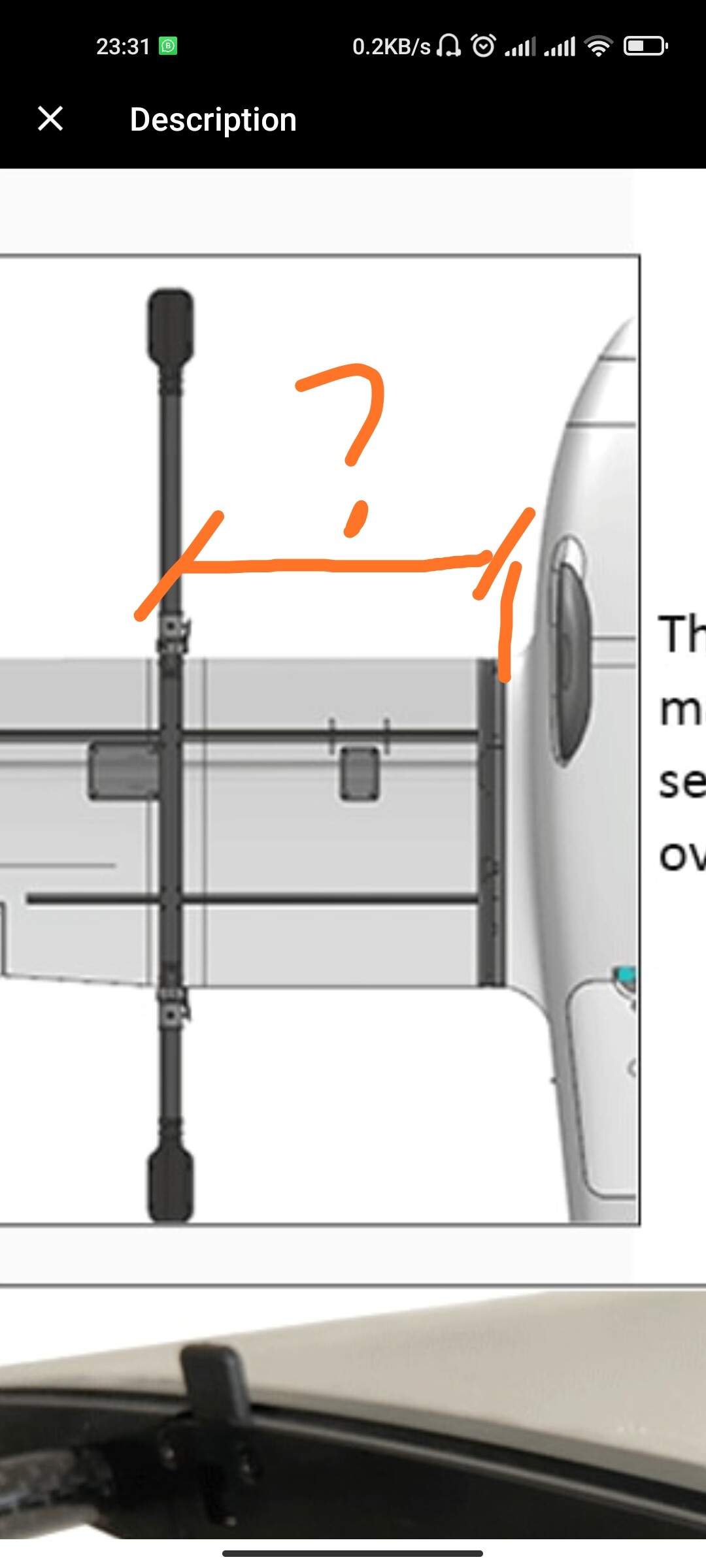
Being inspired with the success of VTOLs, i have started to work on converting my believer to VTOL. Instead of buying freeman wings, I have decided to go with DIY conversion of the believer wings. I am looking for some information from the owners of the striver though. What is the distance of the VTOL arm from the wing joiner?
I aim to use 4112 480kv motors with 25mm square tubes mounted to main carbon wing spars using some aluminium joiners from aliexpress. Maybe I will use a single pusher motor mounter to the front of the fuselage with a DIY mount or in a pusher configuration with a DIY mount on the back of the fuselage.
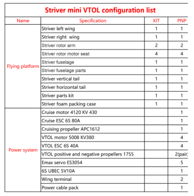
Weight? Not a clue but doesn’t feel overly heavy w/the two 8000s, two cameras, cube, and rfd 900. As for motor, props, etc. they’re straight from the config list …
@mike_E ,
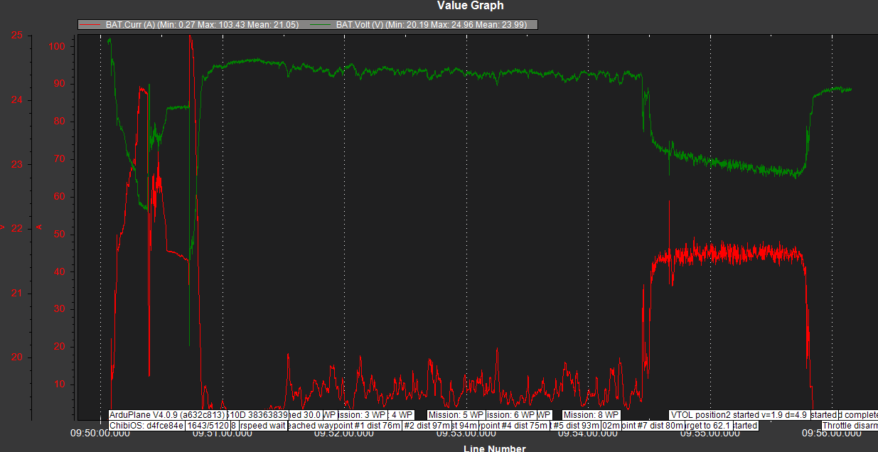
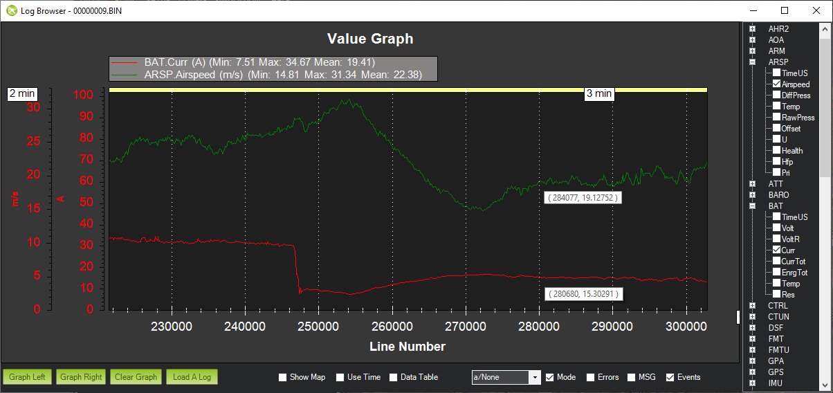
Thank you. I understand that you follow MFE configuration list… I am a bit surprised that this configuration is very efficient… Based on your graph, during mission the aircraft only draw about 10A…
I’m building loong vtol 2160 wingspan with 4+1 configuration same as fixged wing motor in front.
So obviously airspeed sensor silicon tube run through wing upto pilot tube.
How do you manage run through those two airspeed tube in one side.im facing there is no space available to run two tubes.
Is that airspeed tubr order you maintained 2 or either one tube can configure?
The current draw seems within reason. My larger and heavier Fighter 4+1 using the AXI motor draws around 15amps at 19m/s or 42mph. The airframes are very efficient.
Thank you for your reply Greg covey.
But yours is analog airspeed sensor which cable can run through long length without any noise I think so. But I’m using MS4525DO I2C digital protocol.
Why did you used single tube order when pitot tube are very near .
Can you share airspeed parameters setting to clarify myself…
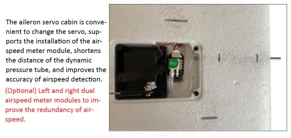
The second tube is only used for static air pressure reference. It is calibrated equally well inside the non-sealed compartment. It makes for an easier installation without compromise.
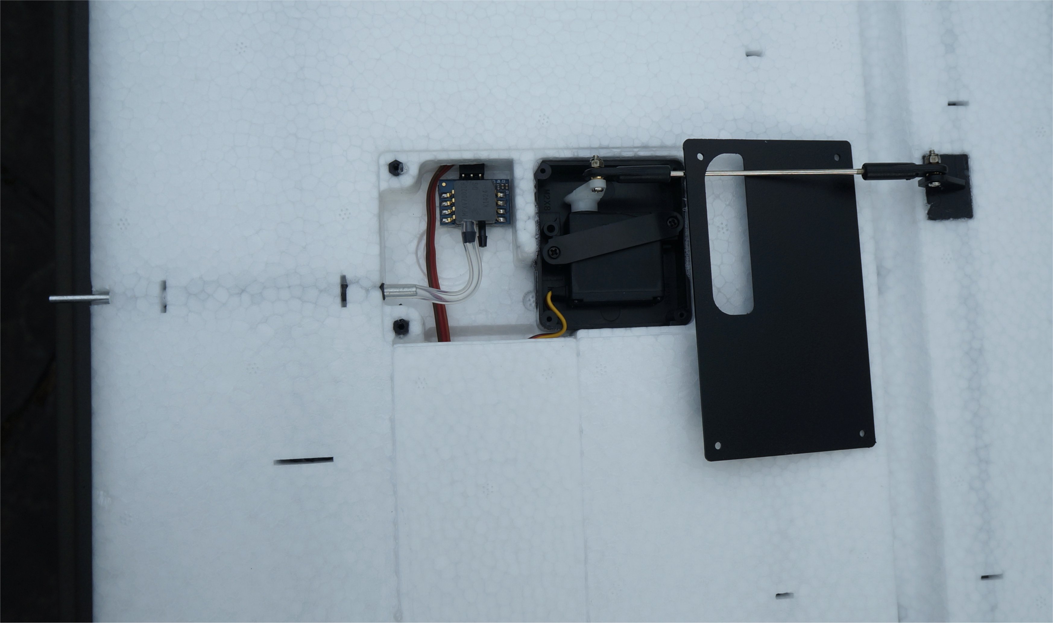
will try but just put it in where the manufacturer intended. There’s a tube already installed. You just open the hole in the leading edge.
[edit] Ooops! Just saw Greg’s reply. My mount looks identical but I used a digital A/S unit and I tied into the aileron for the + and only ran the signal and ground wires through the wing.
Longer flight today. Some one did a Facebook Live video of the landing. I “borrowed” the landing part and posted it. The initial height was 230’ AGL. Also posted the transitions from QStab to Auto and RTL to QRTL. The downward camera didn’t record
The fuselage camera was just on a nylon bolt where the antenna was supposed to go. When I got to the field I realized that location blocked the hatches but it could twist out of the way so glad it wasn’t a permanent mount!
Here’s the TLog if any one is interest so you can see the Amp changes in flight.
This flight was to check out the cameras and telemetry so put it in return to home mode after about 10 min.
Here non- sealded compartment means static port of the airspeed sensor which non sealded by silicon tube or non sealded servo compartment while flying.
What’s is the ARSPD_TUBE_ORDER = X? you have set whether it’s 0 or 1.definitely it’s not 2 sure
Thanks for the videos! I have never flown in an open space like in your videos so it is fascinating to me. In NY, we have trees and houses to avoid.
The ARSPD_TUBE_ORDER should be set to 2 and you need to run a nylon or rubber tube from the active center hole of the pitot tube to the active port on the AS sensor.
If you set 2 then it start taking airspeed data from both the port of the AS.
As your setup have taken only dynamic port of sensor to the dynamic port of the pitot tube.
In that case we have kept static port as open …it taken internal pressure and chance of wrong airspeed value by time to time. What you think @GregCovey
The only time the two ports are equal is when the plane is not moving. The technique works similar to measuring static pressure for altitude using the BARO sensor. Even when covered with open-cell foam inside the plane, the BARO sensor is accurate.
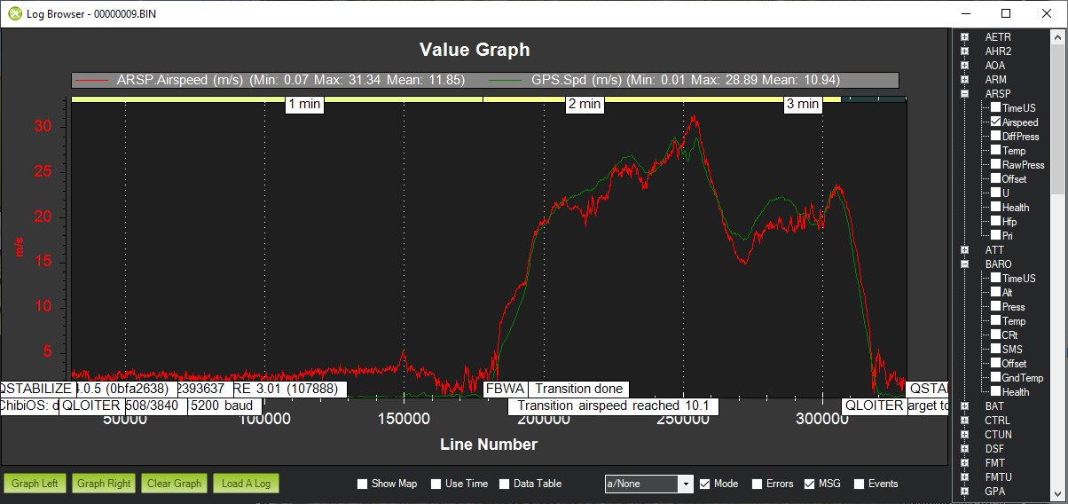
Here is my MFE Fighter VTOL airspeed in QLOITER and FBWA modes. The analog AS sensor only deviates from the GPS speed when wind is involved. The peaks and dips show wind (or plane) direction. ARSPD_TUBE_ORDER is set to 2.