OK… a couple of hours later…
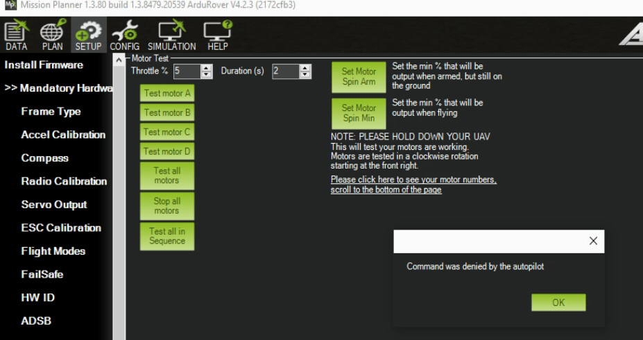
I get “Command was denied by the autopilot”.
The message window shows this:
28/05/23 12:39:23 : Motor Test: Safety switch
28/05/23 12:38:37 : Motor Test: Safety switch
28/05/23 12:38:20 : Motor Test: Safety switch
28/05/23 12:38:14 : Motor Test: Safety switch
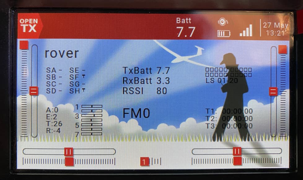
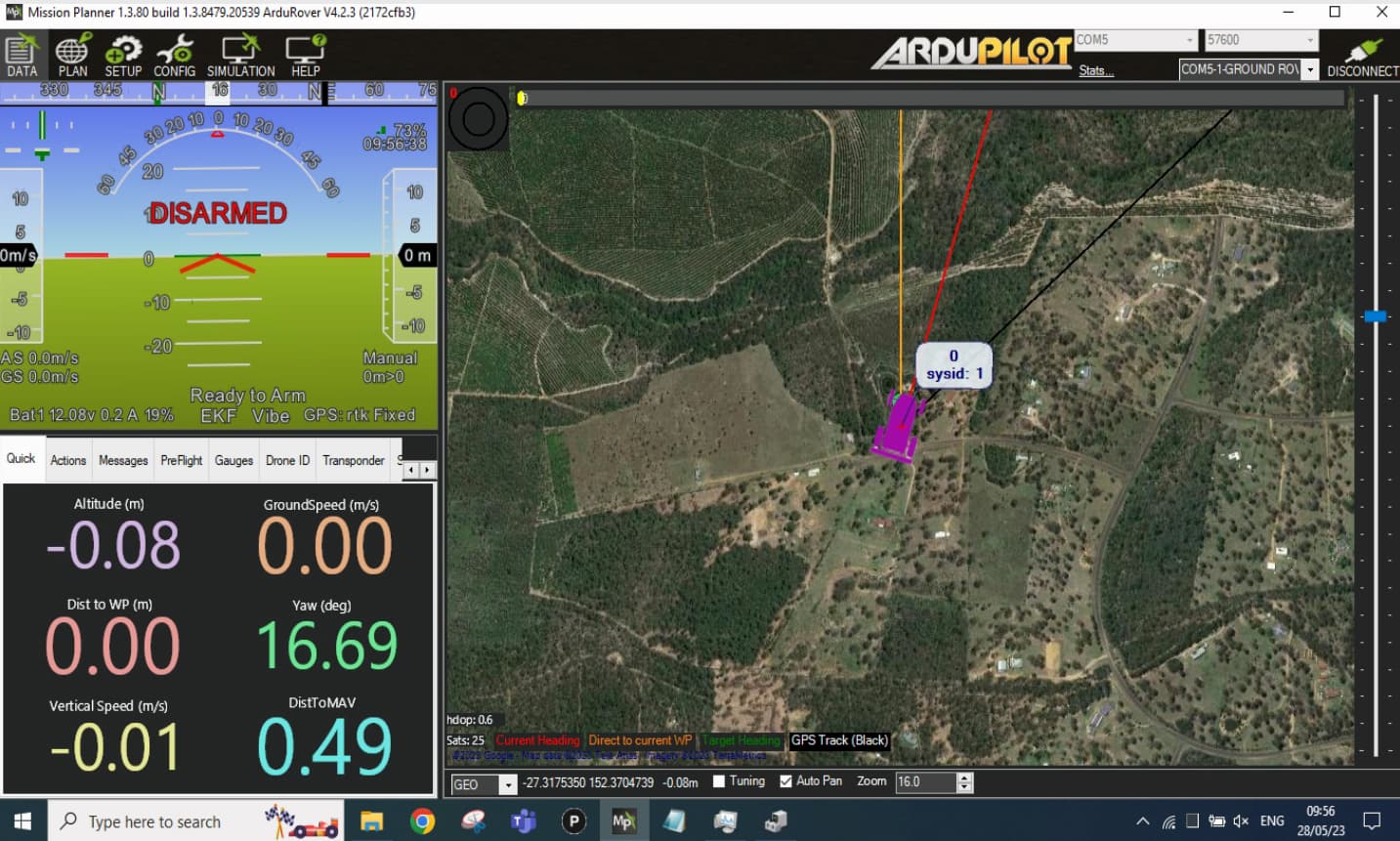
Mission Planner says: Disarmed".
Well, I rebooted the flight controller, and the messages have changed to:
28/05/23 13:15:32 : Throttle disarmed
28/05/23 13:15:21 : Throttle armed
28/05/23 13:14:30 : Throttle disarmed
28/05/23 13:14:26 : Throttle armed
28/05/23 13:14:25 : Throttle disarmed
28/05/23 13:14:23 : Throttle armed
28/05/23 13:14:17 : Throttle disarmed
28/05/23 13:14:15 : Throttle armed
28/05/23 13:14:02 : Throttle disarmed
28/05/23 13:14:00 : Throttle armed
However, still no servo movement. 
Further playing with this…
I noticed that if I set the throttle to 50% and for 300 seconds, which arms and then arms the system, the log file only records ~30 seconds.
28/05/23 14:06:19 : Throttle disarmed
28/05/23 14:05:47 : Throttle armed

28/05/23 13:58:57 : Throttle disarmed
28/05/23 13:58:22 : Throttle armed
Things like this drive me nuts. I sit here checking the servo ports for signals, while the darn thing has long stopped testing motors.
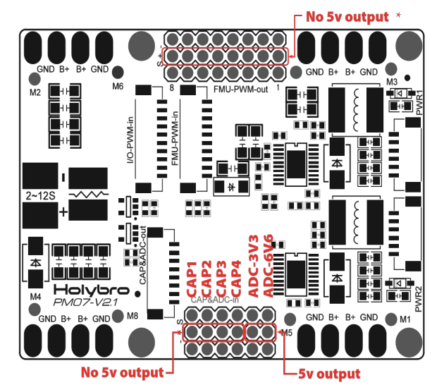
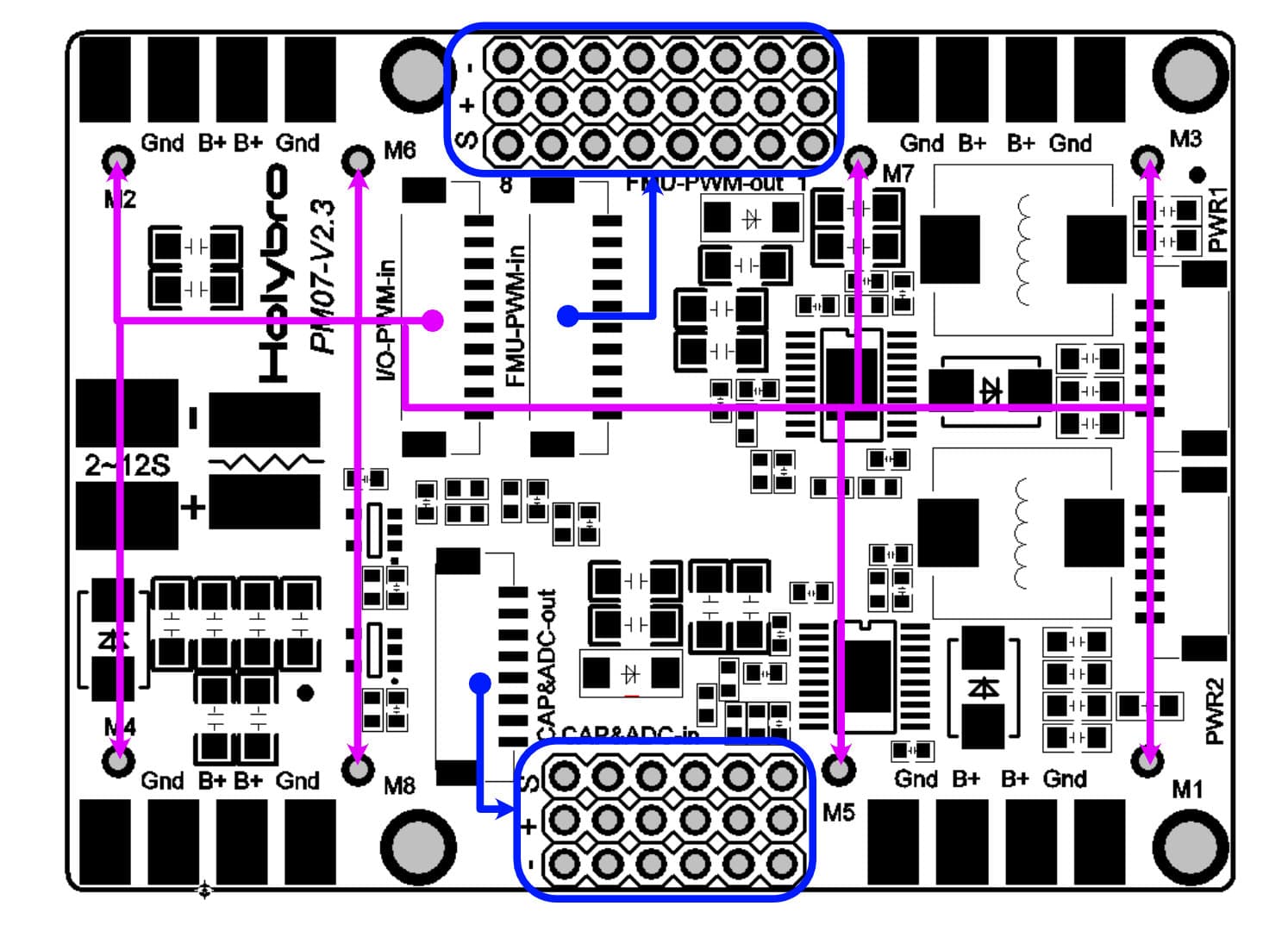
After lots of research I found the picture above, which implies, when using the I/O_PWM_IN (coming from the Pixhawk4), the purple connections ought to be used. I had happily connected my servos to FMU-PWM-OUT.
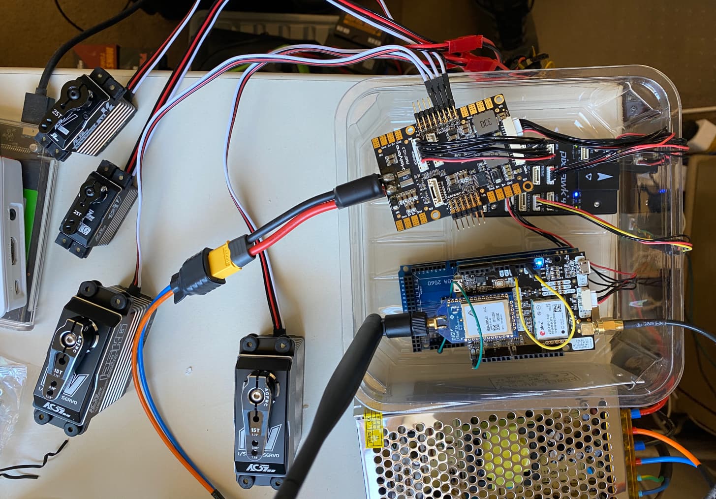
Connecting a servo to the M1 output, the servo would work.
- M1 sends signals… forwards, backwards, on left stick that auto-centres; however, the servos react slowly
- M3 sends signals… left, right on the right stick, these react very fast, as per stick movement.
Why this difference in movement?
M1/M3 seem to drive the servos for the hydro stats.
At last some success!. 
Now where is the throttle output (will test this shortly).