Hello,
I’ll make an attempt to briefly describe the issue I am having. I am working with a Pixhawk 4 that is paired with a PM07 distribution board. I am currently able to get everything to work, except for the servos. When I have tried to get the servos to work, I have the PM07 connected to a 2 cell Lipo (the electronics are not installed in a plane yet), and I am able to connect to the Pixhawk with Mission Planner using a telemetry radio. I am also able to connect to the Pixhawk with a FrSky Taranis Plus transmitter connected to an X8R receiver using the sbus port. Once everything is powered up and connected, I am able to get a GPS lock, monitor air speed, arm the pixhawk using a 2 position switch, change flight modes using a three position switch, and then rev the motor using the throttle stick on the Taranis. All other stick movements only show up in Mission Planner when I monitor radio inputs.
Here are some things I have tried to troubleshoot the problem.
checked all servo connections to make sure they are plugged in in the proper orientation.
I do not have a safety switch, so I disabled the safety switch parameter and turned off the safety switch pre-arm check.
I checked the PWM output and input cables going from the Pixhawk to the PM07 to make sure they were properly connected.
I checked the radio calibration and servo assignments to make sure that inputs are being detected by the pixhawk and that channels are mapped to proper servos.
I checked the servos to make sure they work on another device.
I checked the voltage on the BEC wire coming from my ESC to ensure that it showed 5 volts when the battery was connected.
I then connected the BEC wire from my ESC to the servo output rail on the PM07 and checked the rail with a multimeter to ensure that 5 volts was making it to all of the servo connections.
I am now running out of ideas. I feel like there must be a parameter setting that I am overlooking, but I cannot find information about anything else to check. Please let me know if there is anything that I am overlooking. I also noticed that some people share their parameter settings and other data to help people troubleshoot. I would be happy to do that, but I am not sure how to share those files in a neat and tidy way. If the information would be helpful, I am more than willing to learn how to grab those files and share them. Thanks in advance for any guidance that anyone has.
Also look at the servo output tab of Mission Planner to make sure you have all the servos setup on the correct channels and are moving when you move the RC. Post a parameter file and maybe somebody can see something.
Here is the param list that I have set at this time. When I checked the BRD_SAFETY_MASK param, it is set to 0. It didn’t show other options for changing that parameter. PX4 Params.param (16.6 KB)
You can check the raw values there is a radio tab and an output (or servos or something) tab so you can see there if the pwm is moving. Access from the actions tab down the bottom left
Or you can probably see the pwm from the radio config area maybe.
If you have power on the servo headers its usually arming or safety of something holding you out
We checked the radio tab and we could see a radio signal going to the Pixhawk and the bars were also moving on the output side of the screen as well. The sticks on the transmitter were also moving the correct channels. As you said above, I am beginning to think that there is a parameter change that needs to be made.
Today, after confirming that the Mission Planner Raw Sensor View showed signals coming into the Pixhawk and going out of the Pixhawk to the PM07, I went to the BRD_SAFETY_MASK param and selected the channels that should operate my servos. The value of the parameter changed from 0 to 13. I also changed out my FMU/PWM cable for a new cable (just in case) and removed the I/0/PWM cable, because I was fairly certain that I didn’t have anything being driven by that signal. My servos still don’t work, and my motor stopped working as well. Does the I/0/PWM cable provide the signal for the esc’s? Anyway, the BRD_SAFETY_MASK param did not seem to solve my problem my problem. I’m still feeling confident that there is a parameter out there somewhere that I need to change, but I haven’t taken the time to read through all 50,000 yet. I appreciate the pointers that I have received so far.
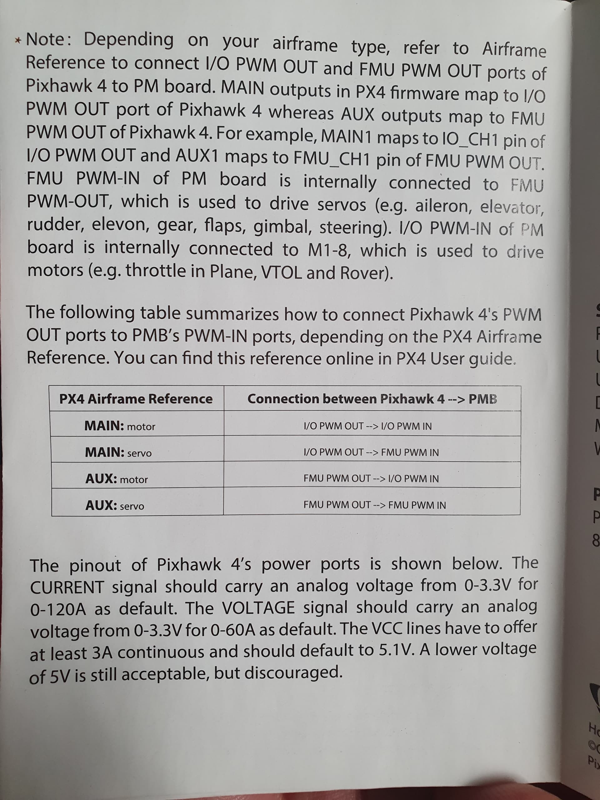
Ok the first 8 channels go to the s1 -s8 pads on the pm07 these are designed (when using pixhawk4) to drive esc but only because of their location, then ch 9-16 are designed as aux channels that go to the servo pin header for servos and auxiliaries. I just swap cables as i use it in a fixed wing. You may well be looking for pwm changes on ch9 while manipulating ch1
So when I am making changes in Mission Planner, I need to set channels between 9 and 16 to operate my control surface servos. Changing channel settings on 9-16 in Mission Planner will then send PWM signals to the FMU/PWM out pins on the PM07. Does this sound like I understand you correctly?
Hi, you can just cross plug the cable from IO PWM on the Pixhawk 4 to FMU PWM on the PM07 to get the first Ardupilot channels connected to the servo connectors on the PM07.
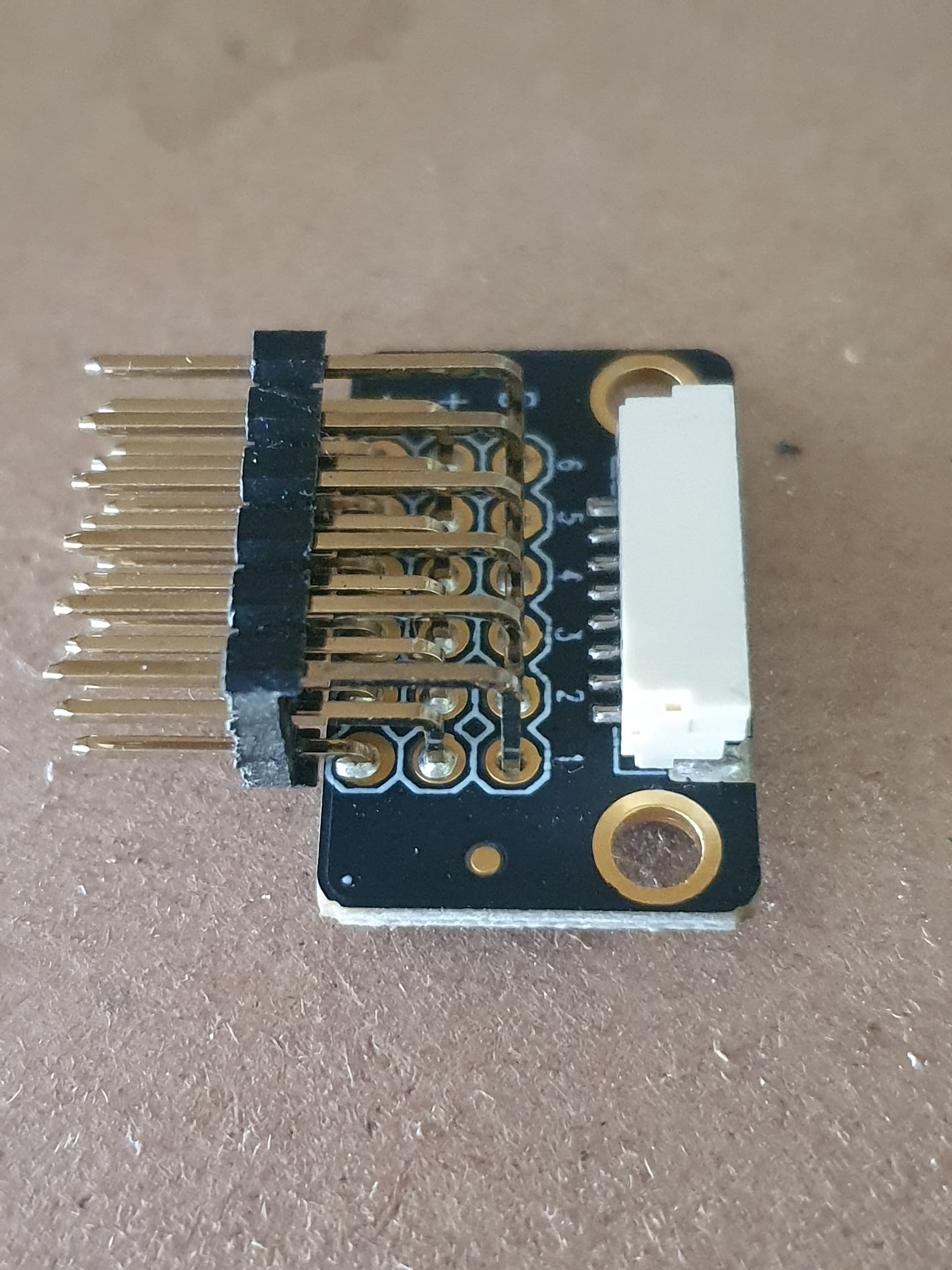
Yes swap the plugs, i actually use the small separate servo pin header board for servos and got rid of the pm07 completely as it is fully designed for a copter and i put a small power module instead that just does volt and current measurement plus supply the pixhawk .
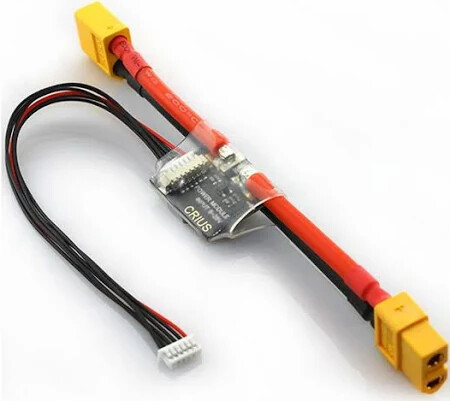
Brilliant!!! Swapped the I/O PWM and the FMU PWM wires, reassigned my throttle to Channel 10 instead of Channel 2, and everything works! Thanks so much for all of the help. I feel like I have a much better understanding of how all of this comes together now. I included an image of a Power Module. Is this what you were saying that you use, Scott_Nunan, to power a single-engine plane instead of the PM07? I can see how it would really simplify things. The PM07 that we used was laying around the shop at the school where I teach, so we decided to use what we had laying around, but the smaller power module would be so much more efficient in so many ways since we are not building an octocopter. Thanks again, everybody! I’m looking forward to seeing our creation fly finally.
Yes i use that for a power module and just the included simple plug in 90 deg header board for the servos, you can plug it into the io pwm out and have the first 8 channels available like normal. I wish they sold the pix4 in two version, the existing one as a ‘copter’ controller as this is what the hardware suits, then a separate ‘fixed wing’ version with a normal power module and just pin header boards for the pwm.
The description is very confusing but once the wires leave the fc you can make them go where you want and connect however you need.