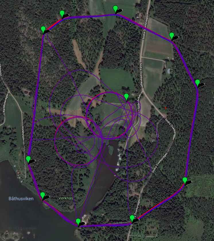
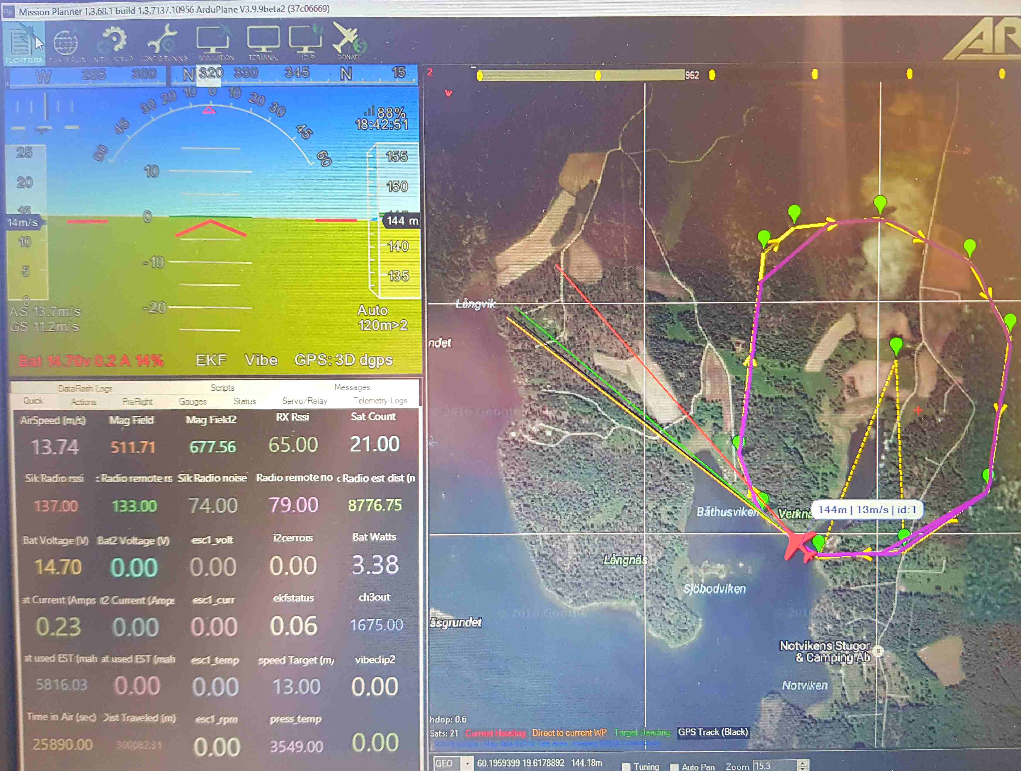
I had bad telemetry in the northwest corner of the 2500m round waypoint, bad placemend of ground antenna,
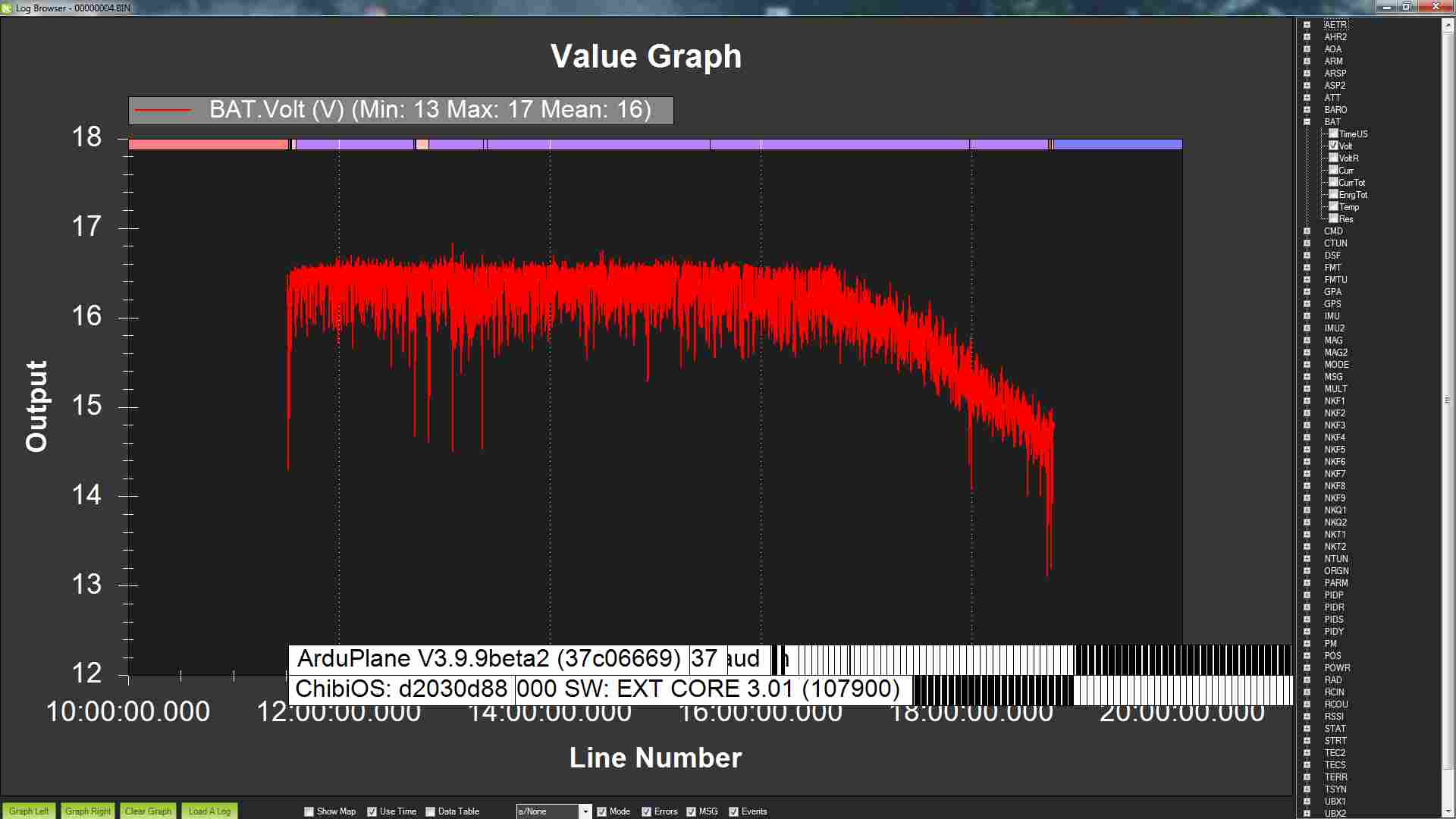
Battery voltage followed the decresing sun angle. Decided to land after more than 7h flight. Should have started earlier in the morning .
Thanks, a week later I did a 520km 11h flight. The genesun MPPT are easy to use, but remember that the solar input and battery (load output) can have common ground or common positive. Genasun GV-5 have common positive. My guess this is why Daniel (rctestflight) are having problem with measuring solar cells output voltage and current.
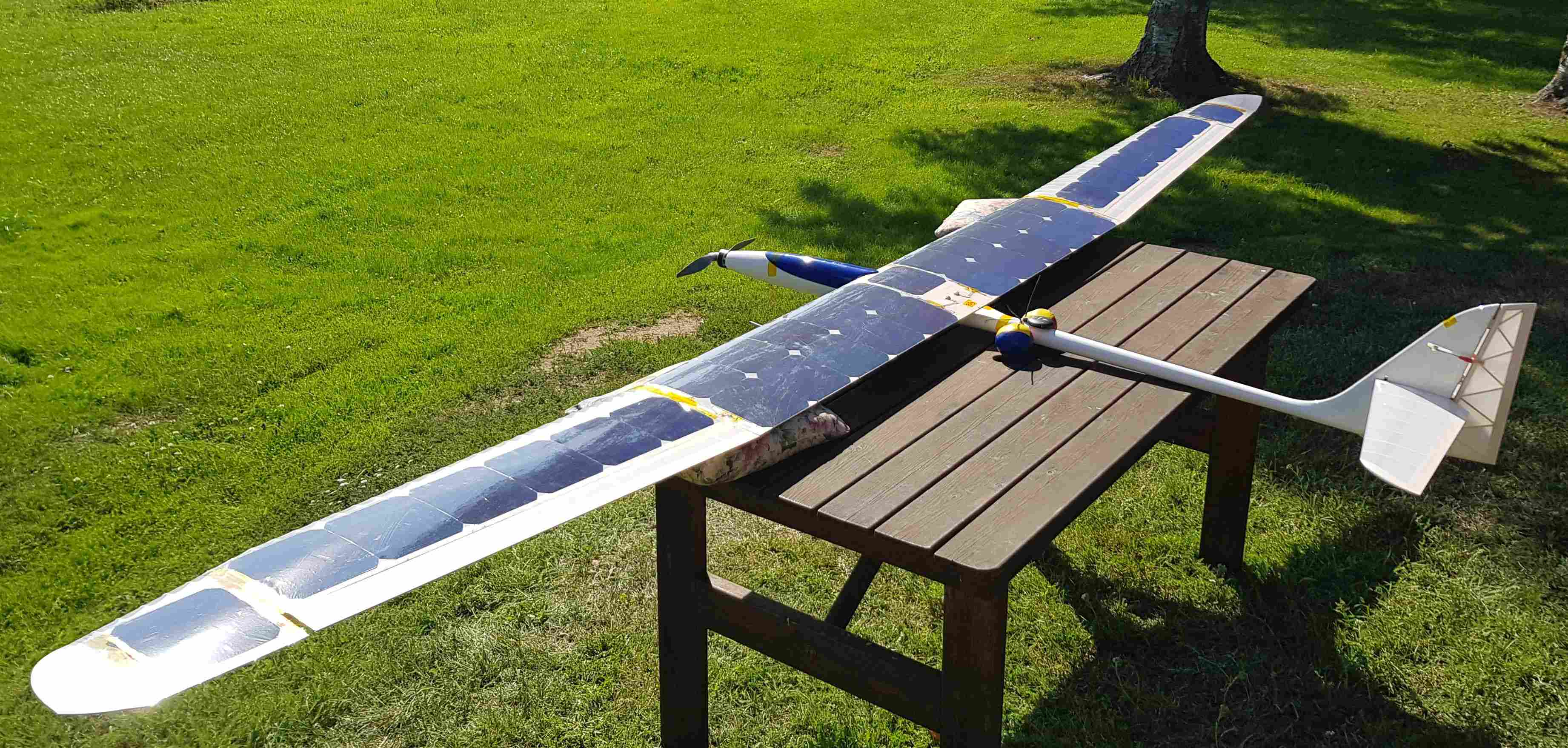
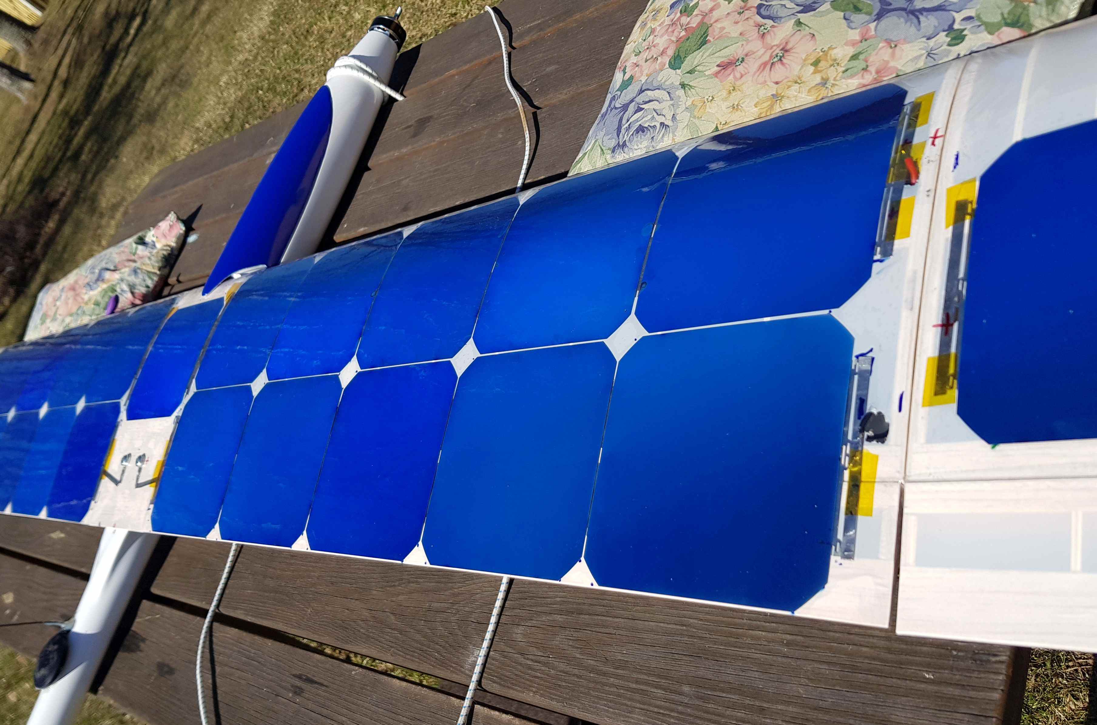
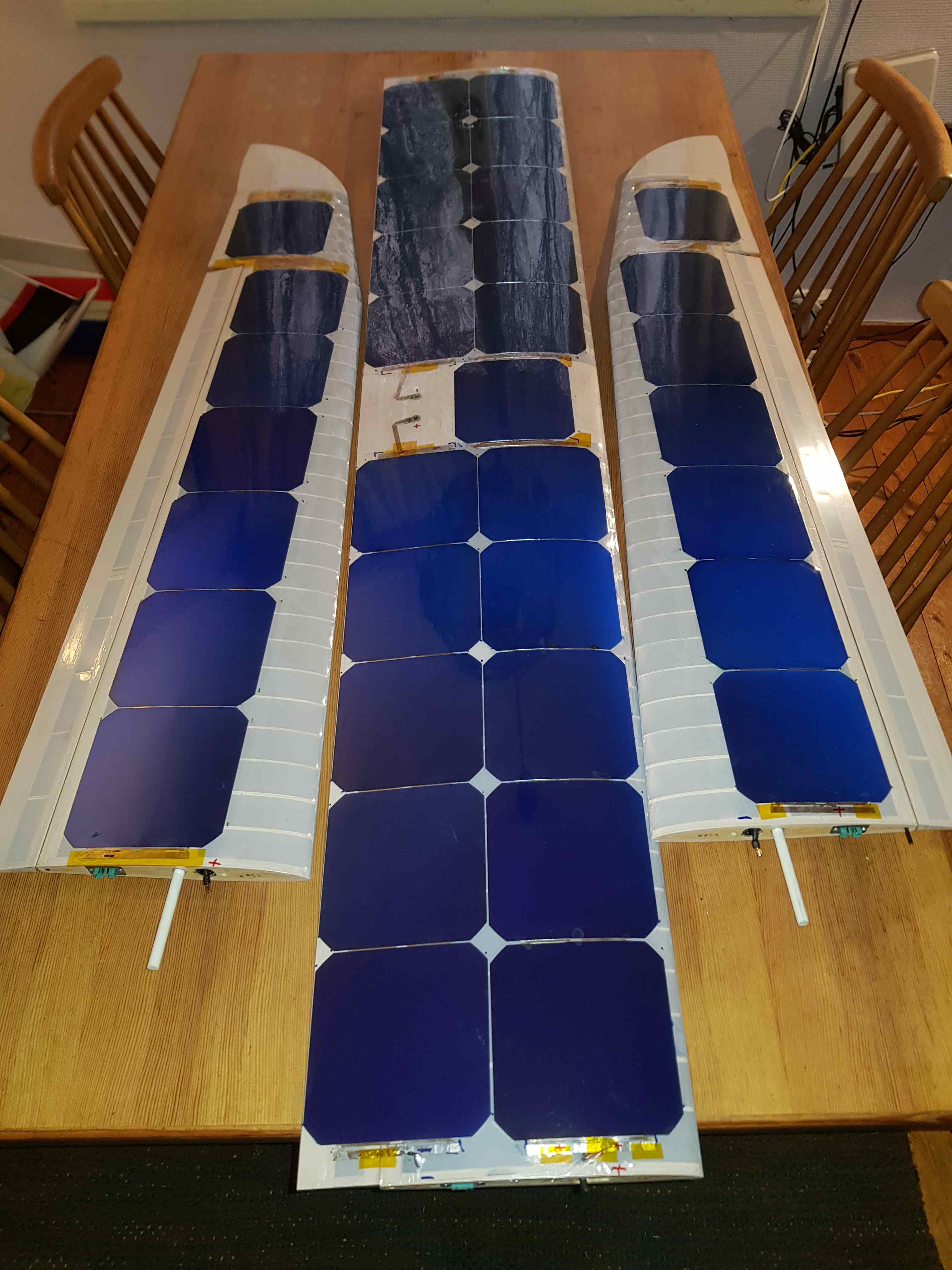
I tried multiple ways of attaching solar cells to the wing. My best solution so far, were implemented on this plane. I started with a covered wing, Oralight white. Then marked the location of solar cells. Brushed on ORACOVER AIR Adhesive on the spots were no solar cells covered the film. Then I placed the solar cells onto the wing with minimum fixation. I used Polyimide tape and some thin CA at selected spots. Then I covered the top side of wing and the solar cells with Oracover air. This to avoid adhesive on the solar cells. I cracked at least two solar cells during the process but because Maxeon C60 uses solid copper back and all connections are on the backside of cells. I did not detect any loss off output power.
It is always cramped inside a glider but there is room. I flown it with a battery 4S3P NCR18650GA 615g and maybe there is even room for a extra 4s1p NCR18650GA 208g. But the center of gravity will then be hard to adjust. And the extra weight will also have negative effects.
.
The log values from power module current measurement are off because I placed the power module close to the battery and the MPPT delivered current are not measured also when MPPT delivered current that charged the battery power module shows zero current even if it is negative. I was planning to also use the current sensor in BLHeli32 but did not managed that.
My measurement on a cloudy day shows 25W-45W for level flight including electric. Little hard to estimate, nonlinear current sensor and unknown amount of thermals. I measured the electronics power consumption and it were higher than I expected. I don’t remember exactly, but Pixhawk consume 2W, RF900x set at 100mW 2W, 4x Servos 2W average, BEC and other sensors 1W. That’s why I didn’t have a FPV Camera. Electronics consume up to 30% of total consumption at level flight.
Even with the adhesive free covering I detected a significant loss of efficiency. But were never able to measure how large, guess 80% output power compered to no covering. But with optimal angle and 800W/m2 solar input I still tested that the GV-5 maxed out at 5A. But I still decided to use GV-5 because of smaller size and weight, instead of switching to GV-10.
Good advice, some years ago I tested with Allegro ACS758 +/-150A on a quad. But got worse resolution than the 60A power module because average current draw were 15-25A on that quad. But newer variant with optimized range for the solar plane should be optimal (maybe ACS730 +/-20A).
Congrats on a couple great flights! Agree you should add ArduSoar to your arsenal, and fly even longer, further, and/or with smaller battery. Thermal up, and regenerative braking on the descent? What was your furthest distance from home on either flight? Also, I was a bit surprised by the 30% of total consumption going to electronics. I’d think one could cut that back some, maybe 25% or 20%?
How sunny/cloudy was each day?
I have a Gracia 3.2M and the Holybro kit, and have been thinking for years of ArduSoar + PV cell’d wings.
I agree that ArduSoar should be on my arsenal, but generally when you have thermals you also have lot of sun. Also it is difficult to use ArduSoar effectively and follow the rules when you are limited to 150m height. Furthest distance from home was about 500m line of sight.
I agree that 30% were a aggressive number. But power consumption of 7W for electronics were not. And also if you are soaring that percentage are 100%
You can save almost 0.5W by disabling the multicolor LED on Pix32
Both days were sunny almost no clouds, but some heat daze. Peak sun angle from horizon were 50 degrees when I landed 10 degrees and estimated sun direct radiation peak to 700-800 W/m2. I am flying at 60 degrees north
About your loss of efficiency of your panel due to your covering. Do you have by-pass diodes installed at all? Depending on the configuration of the panels series/parallel there can be significant effects of localized shading and cells being at different incidence angles on the airfoil. Or even lower performance cells in the string bring the whole string down.
Thanks, no I do not use by-pass diodes. All 35 cells were connected in series to get the input voltage the MPPT controller needed to charge a 4s2p NCR18650GA pack. My thinking was to keep it simple and thin. Also, when you fly higher than the treetops not much to shade individual cells. If you have high camber wing and solar cells on whole upper surface combined with low sun angles, maybe you could benefit from multiple strings of solar cells. I have noticed a difference in output power from the solar cells when flying towards and away from the sun. The angle of the trailing edge combined with the wings angle of attack and low sun make a big difference. If sun is at 10 degrees and the solar cells are at 10 degrees, on this plane the solar cells will produce 25W when flying away from the sun and 0W when flying towards the sun (If only considering direct sunlight). But it is difficult to only fly away from the sun when needed to be line of sight
You’re correct about shading mostly being a sunset/sunrise problem, but do consider adding by-pass diodes eventually. Unless, you characterize them yourself and reject cells or trust the binning on the cells they can have quite varying V_mpp points. For first steps it is not a big deal. But as DIYers and engineers we always want to get that extra performance out
Good luck on figuring out the encapsulation methods that always seemed like the trickiest part! When I worked on such things, we eventually gave up and paid someone else to do it.
So, you are saying that the MPP points are so different between cells from same batch during same light that bypass diodes will improve performance? I always want to find more performance, but I want to see some data on that. But very relevant if one or multiple cell breaks.
My encapsulation method is far from optimal. Heavy with two layers of covering film, there is some deformation of wing profile, too high losses, very week protection of solar cells. Always looking to improve.
When I was purchasing cells long ago the company gave us a range for which the cells efficiency was guaranteed to be within. I believe this was between 25-28%, but it could have been worse since they were reject space grade cells. When these cells got binned later most were 26-27% so if you grouped them randomly you would have lost say 8-10%. What solar car teams and solar aircraft generally do is have their encapsulator do an extra binning step so that each series string has the same efficiency.
In your case whatever is the lowest efficiency cell is going to dictate your best performance.
 .
.


 What was your furthest distance from home on either flight? Also, I was a bit surprised by the 30% of total consumption going to electronics. I’d think one could cut that back some, maybe 25% or 20%?