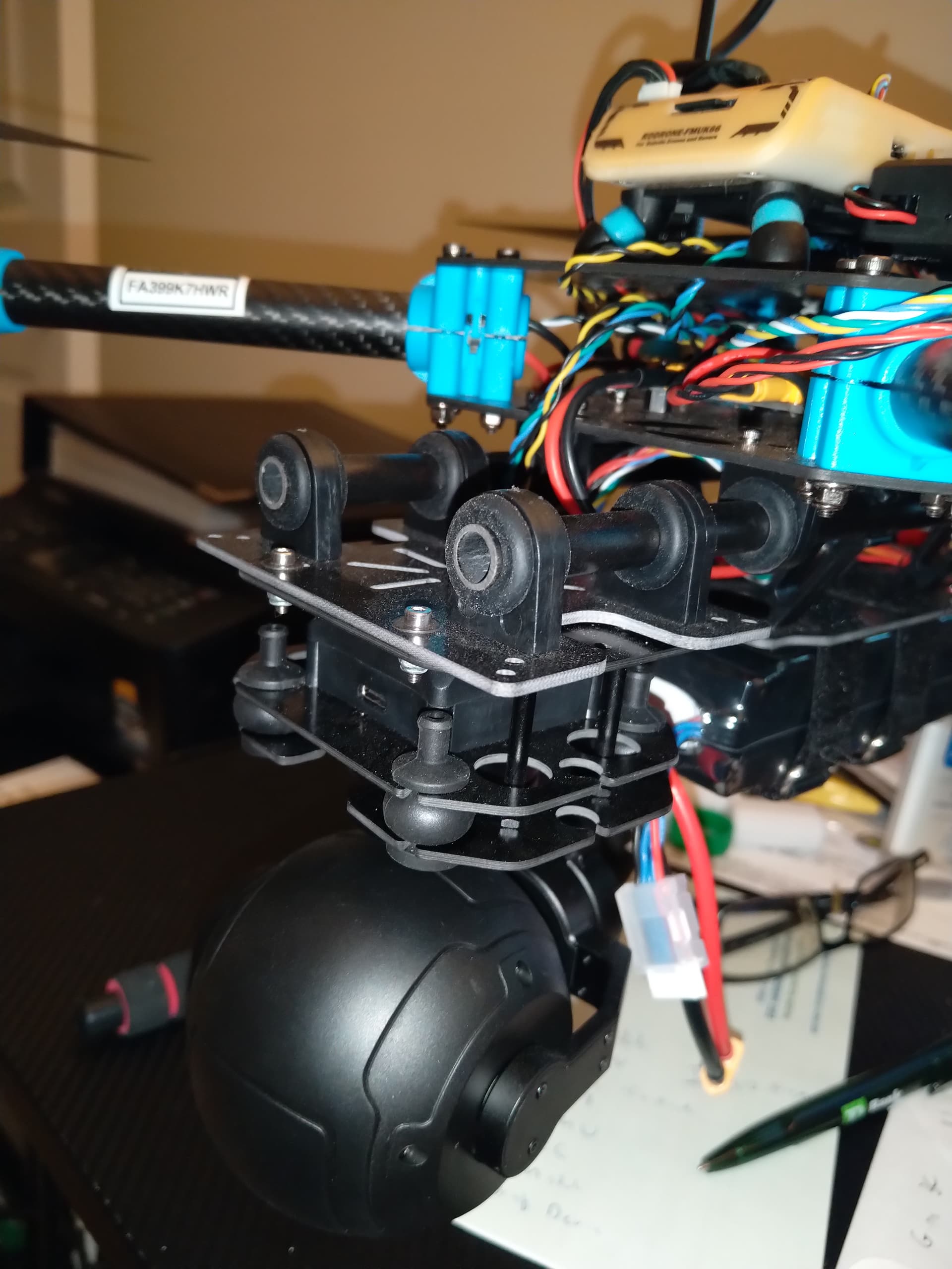
First pic is basically the skyhunter front end! I will mount it even further towards the nose so as to get more downward video! Thanks you i appreciate the pics.
You’d be surprised how few grams imbalance can make it drop performances. If you can design a 3d part with same weight and same cog than you are all set.
I want SIYI to do the design, TBH. Think that this is reasonable to expect.
2 Likes
I think for good customer relations SIYI should produce A new back plate and distribute it free of charge to those that have the wrong back plate
Chinese companies will never do that. They will probably modify it than tell you to buy the new version.
@Hacky @Marc_Dornan @Mark_Rosser @MartyMcFly @MshUav
Thanks to everyone’s attention.
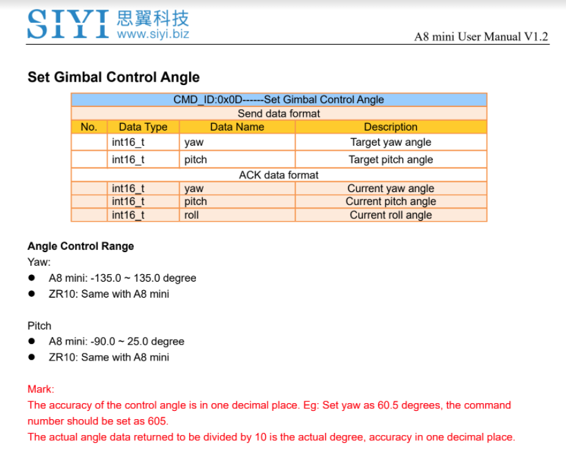
According to my experience, the chance to let the camera box hit the motor plate is very low when the gimbal is powered. Only when it is under following mode, tilt anle is 45 degrees, roll angle is more than 30 degrees (software limit of the roll axis), and the gimbal does not center automatically after reaching to the limit position.
However, we are not going to ignore it.
The team will look deep into this issue and will offer a solution considering the situations you have mentioned here and our own ideas. Please also understand that the final solution cannot be quick since it is something physically.
And we hope that customers who have received A8 mini or are going to receive A8 mini can actually test it under the conditions I mentioned above if you are worrying about this problem. If it was indeed very difficult for you to use the gimbal because of this little issue, please feel free to write to support@siyi.biz and we will put you on the contact list and notify you immediately with the final solution when it is ready.
3 Likes
Mounted underneath a plane pointing down 45° and the plane banking 31° degree roll during a turn is easily reachable.
Design is flawed, wonder how you didn’t catch it before shipping to customers or maybe you did…
If SiYi does the same on gimbal as they did with problems on radio they released, they will just keep rushing out new products, leaving old ones die.
When top mounted there is no issue here and the gimbal cannot touch the yaw arm under any circumstances. Only when mounted on a quadcopter underslung is an obstruction possible. So plane users need not worry about the gimbal striking the yaw arm. It does seem like a good option for a plane or rover gimbal, but I have yet to try it. I agree it is odd to have a gimbal striking at near 30 degrees roll but I do appreciate Siyi’s engagement on these forums.
I have one other question to Siyi – can we get a few more degrees of roll stabilization in ‘upside down’ mode? Say 38 degrees?
Also can we use this gimbal with gyroflow? Are you including IMU data in the video file?
i wrote “underneath a plane”, so actually yes.
Sorry – I misread your post. Yep – that’s a problem.
I build VTOL always hang the Gimbal underneath, and when flying the pitch is usually at a 45 degree angle and my planes roll is limited to a max of 35 degrees this could be a problem.
Obviously it is in your configuration. Maybe they’ll recall the gimbals and modify them free of charge.
@SIYI Frank, thanks for your statement. I appreciate that you take care.
Still, your “30 degrees software limit” seems to by pretty artifical. Looks to me, that the spec was adapted to that design flaw after it already happened and there was no time left to fix it. Would be very surprising to me, if someone specifies and designs a 3-axis gimbal from scratch with a 30 degree roll axis limit - or did you have only rovers in mind? Planes and multirotors easily exceed 30°.
If you set a software limit, may be that you do not allow external commands to roll the gimbal outside this limit. Fortunately there seems to be (currently) no software-limit that stops readjusting the roll motor, in order to keep the horizon stable if the mount is turned more than 30°. You can test that when the gimbal is activated and hear the motors clicking when the camera case hits the yaw mount.
I desperately hope, that you will NOT issue a firmware update, that also limits this behaviour (and stops readjusting the roll axis to keep the horizon when plane rolls more than 30°). Instead at least I (and probably most of the others early adopters here) would like to go my own way and fix the problem with a modified back plate until you can provide a better solution.
I do not see a performance problem caused by this really minor imbalance of a modified back plate as the gimbal seems to use also encoders to control the position (not only IMU). Encoder based gimbals have much more reserves for imbalances like this compared to traditional, encoder-less gimbals.
Looking forward to a solution by SIYI but until then, will help myself.
Another whish I would have for a redesign of a “A8 Mk.II” is a wider voltage range. Many of my small drones use 3S LiIon batteries (discharged down to about 9V). Currently, this means that I would need boost voltage regulator to provide at least the 12-13V that the current “pre-sale batch” version expects (4S - 6S according to specs).
Hi Frank,
Could you please post a CAD (STL) file of the back plate.
Thanks
Hi All,
I want to modify the camera case back plate shave all for corners off the top of the backplate so they recessed about 100 microns below the camera case corner then fit the new case and then may need to take off that 100 microns of the case corner with a finger nail file will need to put a tiny bit of sealant around the back plate so as no dust gets into the camera case. Here is a link to the SIYI *.STP CAD file
https://drive.google.com/drive/folders/1aSulEJW6OYt8UTtW0osgL20lkXcMuGxp?usp=share_link
The back plate in the STP file is there in four parts including the recessed perimeter on the under side of the plate can someone get the plate out of the file I only have very basic CAD skills. Once I have the plate STL file I can shave the corners with 3Dprints until I get it right. It does need the perimeter on the underside of the plate.
Thanks
1 Like
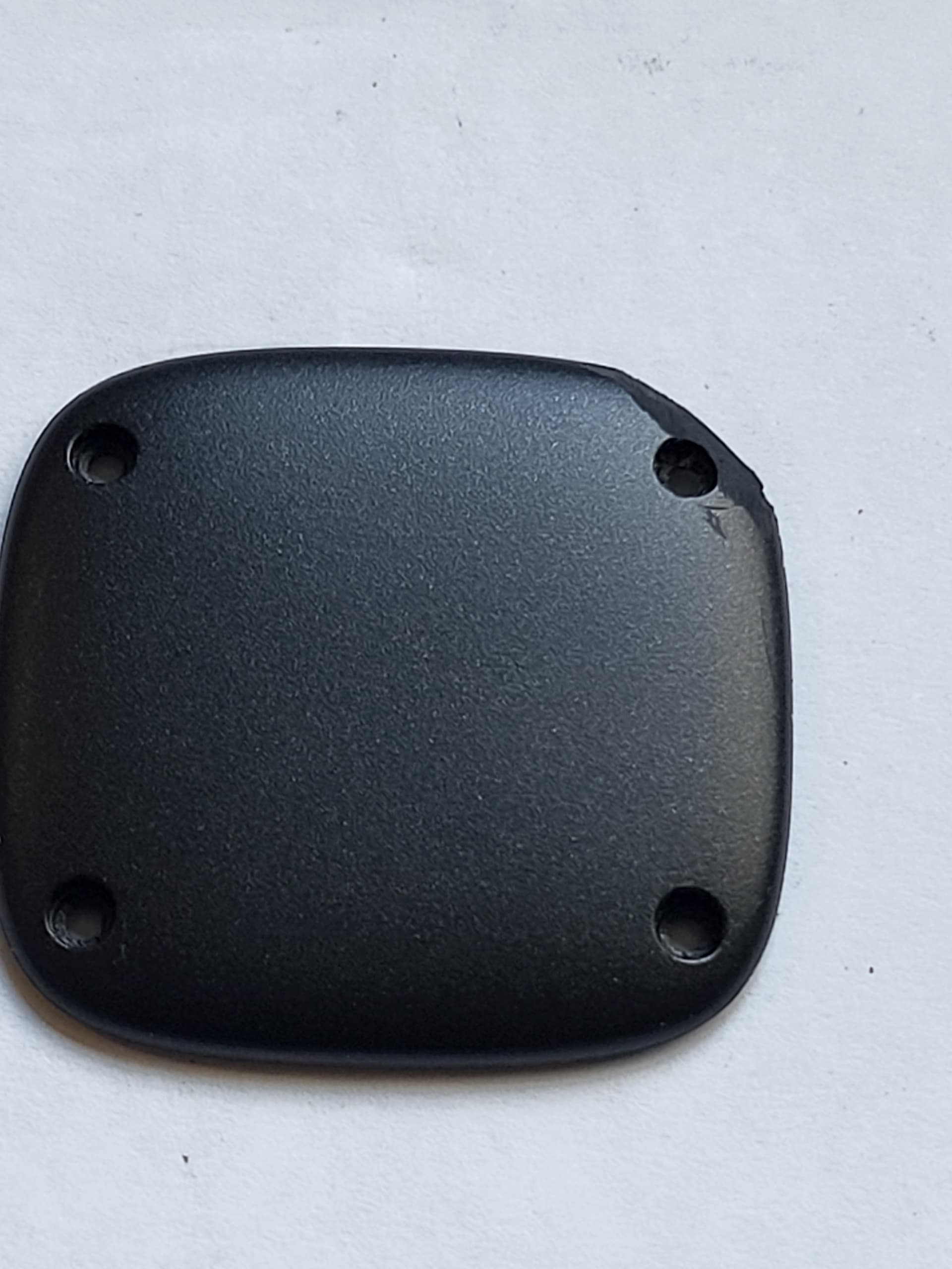
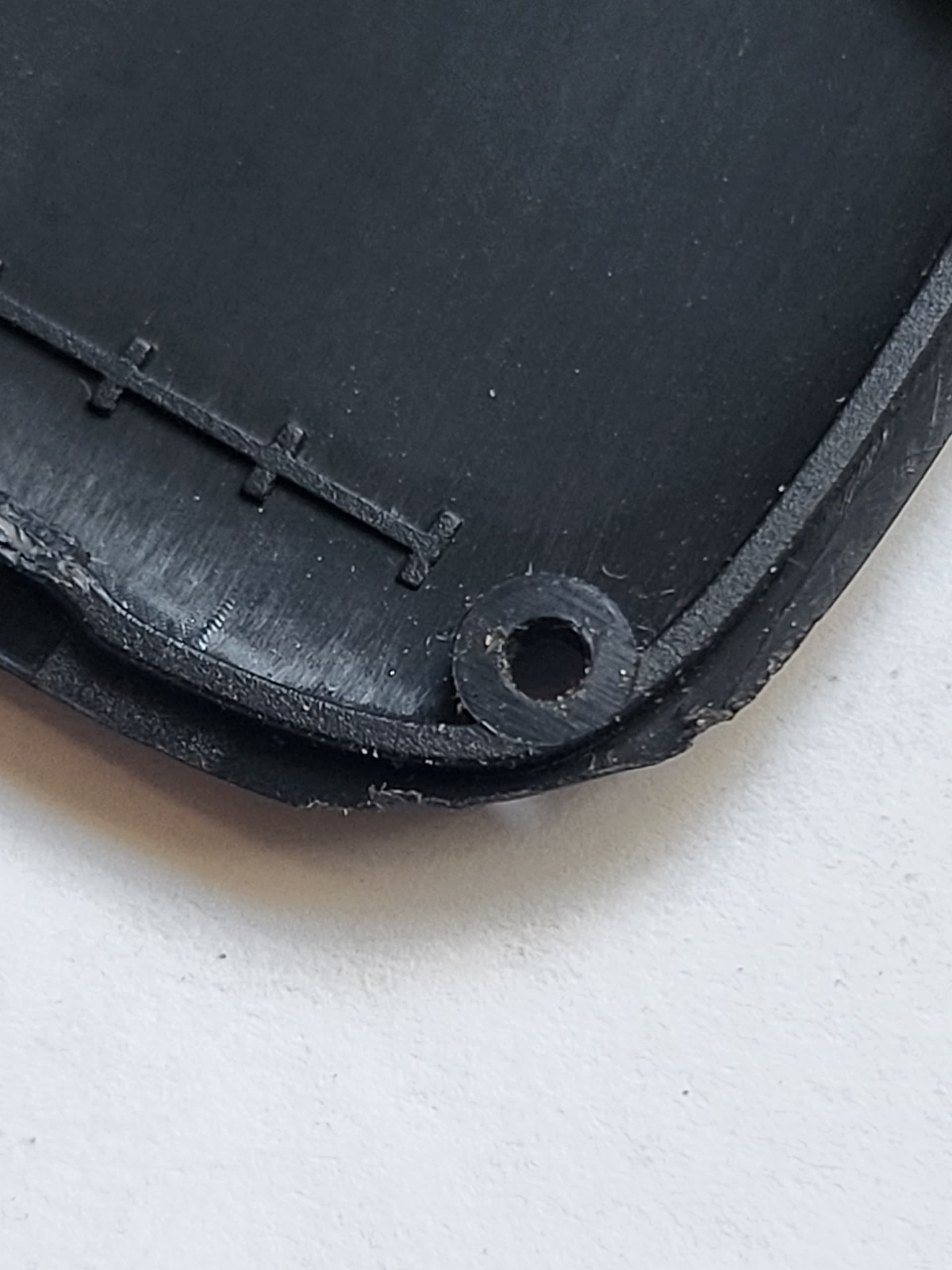
I have found a crude fix. The main problem is more the camera case corner than the back plate. take off the camera back plate ( the camera PCB is held in place by the back carefull it is loose also dont let any dust in) file all four corners as in pic_1 & Pic_2
then re fit the filed plate then take off the case corners until it misses the yaw arm one file at a time until you get it right. Pic_4 is how I tested it works before modifying the back plate
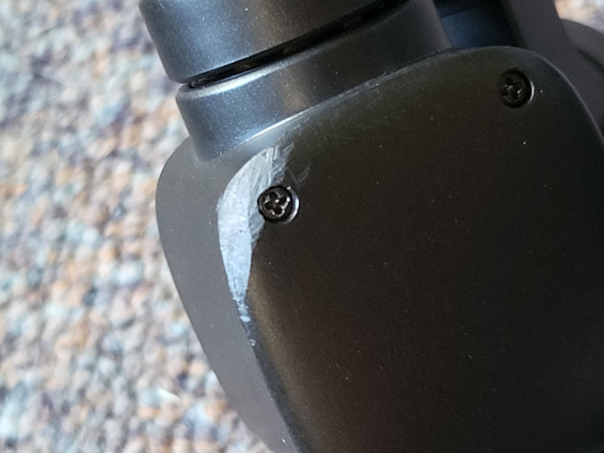

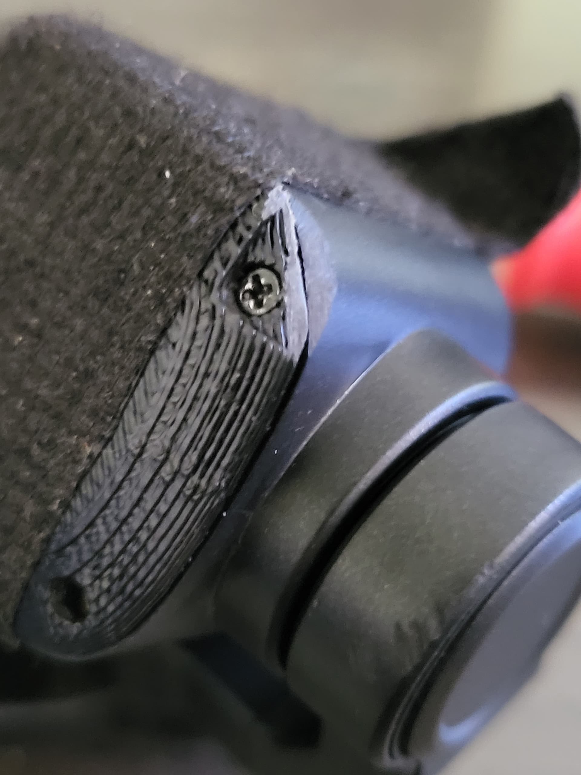
Cant see any other way to fix the issue as the camera case corner needs to be filed as well as the back plate corner
Note: the camera case is not square 32mm x 30mm see Pic-3
wash the back plate after filing before refitting so as to remove any dust
3 Likes
What would be the recommended way to mount this to a Holybro x500 V2 frame? Is there a product that would allow me to connect it to the mounting rails? Or should I buy another payload platform board from Holybro (I’m using the one that came with the frame for a companion computer) and attach the A8 to that platform board? Would that work? Thanks in advance…
1 Like