Hi all,
I want to write the Wiki for using RPM sensors.
I don’t know everything about implementing the various sensors on the various flight controllers out there. So I am creating this thread to encourage others to share their own knowledge and tips. Also, if I have made a mistake in the information I have written below, please do point it out. I will then collate all of the information into a Wiki page.
What I know so far:
In principle, any rpm sensor that outputs a PWM signal can be used by ArduPilot. Common RPM sensor types include:
- Hall effect sensors such as this.
- Back EMF sensors such as this
- Optical sensors. Need an example, and have not got any experience with getting these working.
Note that this guide will be covering external RPM sensors using the AP_RPM library. It will not be covering the ESC RPM that can be obtained using a UART for ESC Telemetry. The wiki for that already exists here.
There are already few forum threads which discuss RPM sensors. The two with the most info are these:
- Thread here
- This thread is looking at getting RPM sensing for IC engines
Getting the hardware setup
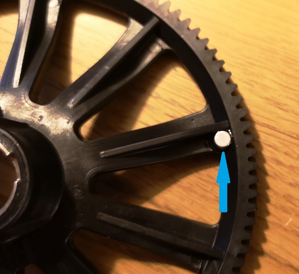
For using hall effect sensors a magnet and pick up sensor are required. Often, a hole or recess needs to be drilled and the magnet glued in. For traditional helicopters the best place to glue the magnet is in the autorotation tail rotor drive gear. For example:
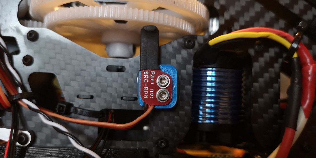
The hall effect sensor will then be installed on the airframe, being careful to ensure that the sensor and magnet are sufficiently close for the magnetic field to affect the sensor. For example:
For IC engines the magnet should be mounted onto the output shaft and the sensor onto the case. For example:
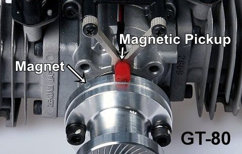
All 2-stroke and 4-stroke ICE will need the magnet and sensor installed for ignition timing. The same sensor can be used to read the RPM in ArduPilot.
The orientation of the magnet does matter. The sensor will only change the output voltage in the presence of one of the poles of the magnet (N or S). The polarity depends on the sensor. To easily identify which is the correct polarity I have adapted an Arduino sketch from diyhacking.com. You can find the sketch here.
To use the sketch, connect the signal pin of the sensor to pin 2 on the Arduino (an interrupt pin). Connect the Gnd to Gnd and Vcc to 5V. Set the detect_on variable to true. Upload the code to your Arduino. Open the serial monitor. All being well, when you bring the magnet close to the sensor, with the correct polarity, the serial monitor will print ‘detect’.
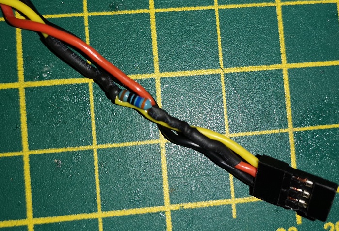
I have found that the hall effect sensors that I have need a pull up resistor to be added. Solder in a resistor (resistance value doesn’t matter too much. I used 360 ohm because I had it lying around.) between the 5v line and the signal line, like below:
It is also worth noting that not all sensors are made to adopt the ‘standard’ wire colouring that you might expect. This sensor for example requires that the GND and VCC are swapped from the norm (i.e. red is GND and VCC is black). So the Arduino sketch above is a good way to debug this and easily swap the sensor leads around until you find what works.
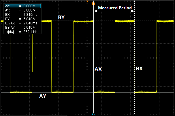
Final note on the Arduino sketch. It will also plot the measured rpm to the serial plotter. To do this, set the detect_on variable to false. Set the number of magnets using the n_magnets variable (for example, some choose to have 2 magnets 180 degrees opposed). and open the serial plotter tool. This offers a relatively easy environment to get the sensor working properly, before introducing the additional complexity of ArduPilot into the mix.
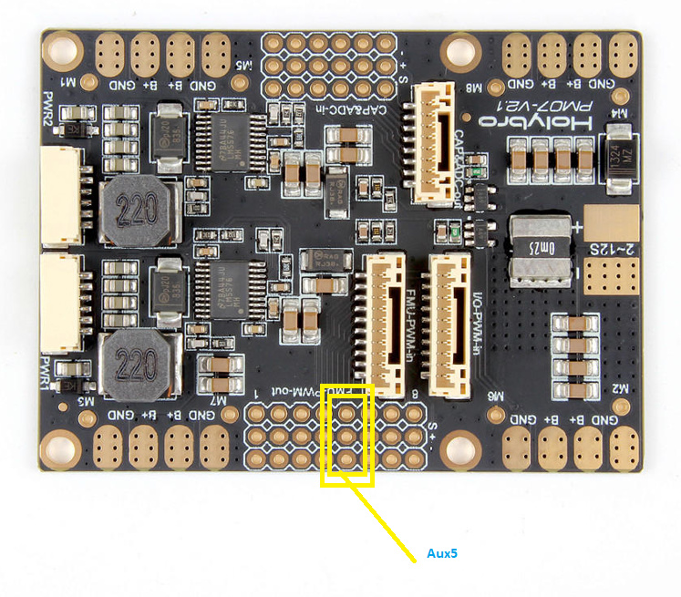
If using a back EMF sensor for a brushless electric motor. Something like this. Hardware setup is straight forward. Simply solder the two input wires to any two of the three AC motor wires. The order does not matter, any two will do. The three wire output then gets plugged into the flight controllers AUX/PWM rail.
Setting up ArduPilot
You will need to plug the rpm sensor into either an AUX port on a Pixhawk, or a PWM port on a different flight controller.
The next step is to ensure that the port you have plugged the rpm sensor into is configured as a GPIO pin to receive a signal input. You can do this by setting the BRD_PWM_COUNT parameter. Set this number to the highest PWM output number you are using. All remaining FMU outputs are then assigned to be GPIO, and are therefore available to read an input. For example, on a pixhawk, setting BRD_PWM_COUNT to 8 will leave all AUX pins as GPIO pins.
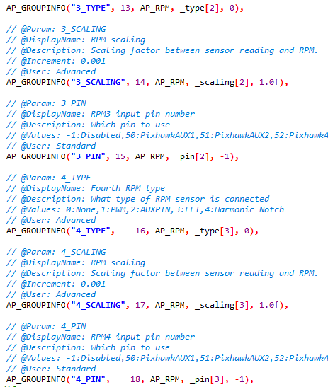
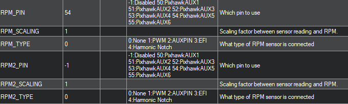
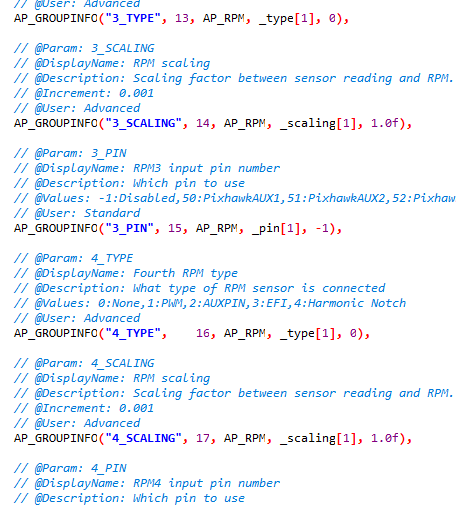
The next step is to let Ardupilot know which pin the RPM sensor is connected to. This is done by setting the RPM_PIN parameter. Note that this is not the pin number as printed on the casing/silk screen but the pin number as it is assigned in the hwdef.dat file. For example, if you are using a pixhawk then Aux pin 1 is set as pin 50. If you aren’t using a Pixhawk, to find out what the pin number is for your board then look through the list of hwdef.dat files here to find the firmware for your board. Then find the PWM out list, and the number you want will be in the brackets of the GPIO() function. For example, for an F405 wing PWM 9 corresponds to 58:
PA8 TIM1_CH1 TIM1 PWM(9) GPIO(58)
If you have multiple magnets then you will need to set the RPM_SCALING parameter. E.g. for 2 magnets set RPM_SCALING = 0.5.
If using the AUX ports on pixhawk then set RPM_TYPE to 2. If using a PWM port on a pixhawk or a different board set RPM_TYPE to 1.
^^^ I am not 100% sure that this is correct. Can somebody please verify when it is correct to set RPM_TYPE to 1. The difference between the two wasn’t obvious to me looking at the code. ^^^
In principle the RPM sensor is now set up and should work. You can verify by plotting rpm1 and rpm2 in the live tuning plotter on mission planner.
Initially, don’t change the RPM_MIN, RPM_MAX, RPM_MIN_QUAL parameters as these could make it appear that the sensor isn’t working at all. For example, if the scaling isn’t correct and the RPM value is greater than RPM_MAX, then the value in mission planner will just indicate ‘0’. Once you are happy that you have got a clean and reliable RPM signal, then think about changing the aforementioned parameters. Keep in mind, if you have two rpm sensors then the aforementioned parameters are valid for both rpm sensors and should be set accordingly to encompass the RPM range seen by both sensors.


 ny tip will be really appreciated. Thank you.