I’ve looked all over the place and found many discussions going back as far as five years ago talking about this but I haven’t as of yet found one that is a completed project.Some talking about hall sensors, optical sensors, some trying to convert the signal to PWM and input to a aux channel and some trying to interface to the I2c bus. Just being able to log rotor RPM in the pixhawk would be great. Is anybody doing this and willing to share how? Motor RPM is important but I think that rotor RPM is what most people would be interested in.
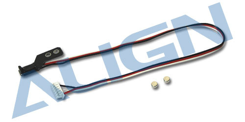
I have the motor RPM working perfectly with a Pixhawk 2.1 which really helps for optimizing efficiency, but picking up the rotor RPM would be more valuable, especially if you could put the sensor on the autorotation gear. I’ve found a few posts on the same topic too, and have located what I think would work, its an Align Governor sensor for $10:

Its intended for Nitro helis, but I think it could work if you pickup the signal wire the same way I got the motor RPM signal wire working through one of the Aux ports. I’m not sure if the autorotation gear is different on the Nitros, you can see the two magnets that need to be mounted on it, not sure if they have molded-in spots in the gear for them or if you simply have to glue them on.
I haven’t built any Nitro helis, but I did find that this sensor mounts on the motor’s fan, and it does have molded-in spots to mount the magnets. So, I think it would be possible to mount these magnets on an electric autorotation gear, but you’d just have to epoxy them on the inner rim of the gear on both sides to keep it balanced. I may try to do this over the winter, just haven’t had time to get to it yet, if I do attempt it and get it working, will post the details.
I found this project where he’s trying to use the I2c bus. I think this would be the best way to go. I used to use a product called “CarbSmart” on my Nitros that controlled RPM with a hall sensor and also controlled the mixture by monitoring engine head temp. It actually worked very well.
I actually just got this one working:
Granted, this reads motor RPM/ESC pulses, so if the motor/ESC fails, you wont get any RPM data, but it’s a simple option if you just want RPM info.
Sorry to revive an old thread again, but is there no way to mathematically calculate the motor RPM from Pixhawk log file data? If you know the specs of the motor, number of poles, amps used, etc.?
Real time RPM data would be nice too but I want to go back through my logs and see the average RPM I was using to hover in Loiter, etc.
Thanks
You could maybe arrive at a very rough estimation using the motor kV, loaded voltage at the time, factor in an efficiency value, and use the throttle out messages in the log to apply a percentage of throttle. But that will only work if you using the throttle curve, or are using a RSC Mode 1 signal from the radio with no governor in the ESC.
Typical calculation would go something like 500 kV motor @ 45 volts loaded = 22,500 rpm x 0.9 (efficiency factor) = 20,250 rpm x 65% throttle = 13,160 rpm.
There is no way this can be accurate because the efficiency of the motor changes with load. It can be at zero rpm and 100% torque at 65% throttle if it is stalled. But it might give you some really rough guestimations for comparison between hover and cruise flight or something.
Real time rpm is most useful with RC telemetry. Just about all RC systems with two-way links support it these days. And it is usually just a simple matter of installing a rpm module on your radio receiver and set up your RC radio to display it on the screen. It is less useful in the Pixhawk logs and/or MavLink to the ground station. Because you may or may not fly with a ground station all the time. But you always fly with the RC radio.
Looking forward to pix can support speed monitoring and implementation of GOV through the ESC speed sensor for a long time.
Thanks for your reply. I’m actually trying to figure out average RPMs on a quadcopter hovering in Loiter because I want to determine the excitation frequency of the motors/props.
I want to know the excitation frequency in order to best eliminate vibration harmonics between the motors and the natural frequency of the frame I’m designing.
I’m not sure if this is helpful but with helicopters if you take an FFT of the gyro signal, it is very clear what the rotor speed is based on the peak in the FFT. Not only do you get a peak at the rotor speed frequency but also at the frequency of the number of blades * rotor speed. Now with Multlcopters, I don’t think the peak would be as pronounced but I would imagine that you would get some wider frequency range with increased energy/amplitude on the FFT. You would definitely have to keep the aircraft in a stable hover so as to minimize the variation of prop speeds.
The only other way I can think of is buy ESC’s with logging capability and download their logs after the flight. At that point it is just matching ESC log to what you were doing in flight or to the pixhawk log.
Good luck!
Okay so Fast Fourier Transform? And what parameter would be the “gyro”? IMU? something else?
Thanks
So it could be just about any of them, at least that is the case for helicopters. I would suggest using the batch logging feature described here.
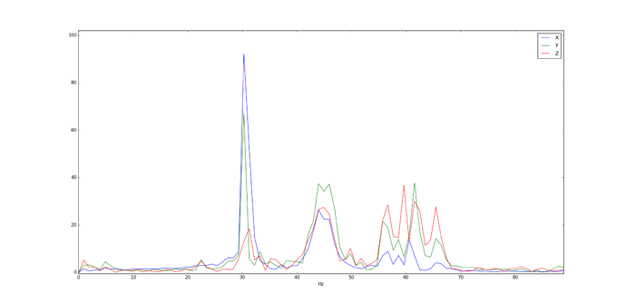
Here is a plot from the sampling that I did with my helicopter. Here is the FFT of the Accels
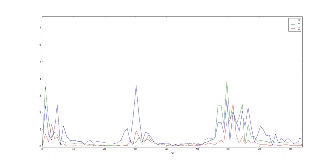
And here is an FFT of the Gyros
My rotor speed was 30 hz (1800 RPM) and you can see the nice large peaks in the X and Y accelerometer. So maybe those two would be your best bet. I have never done this with a multicopter so you may have to experiment to see what signal works best.
Good Luck!
Ahhh, thanks for the link!
I talked to Rob at AUVSI-Denver and he said that Tridge had Rotor RPM sensing input on Aux-5 and governor control working and he thought it was in the Master but I can’t find it anywhere. Maybe its still in a branch somewhere. Maybe someone else could look around and see if it can be found.
I did find this in the Library https://github.com/ArduPilot/ardupilot/tree/88abd34d401456ee9a52d5400e52db377d6bd4ae/libraries/AP_RPM
It talks about setting the input pin and type of sensor and appears to include Hal sensors.
Also, Rob said that Tridge had set up the PID loop code for the governor function and that it would work down to about 10 rpm
Doug,
Rotor speed control using the rotor RPM would be accomplished in the motors heli RSC library. I am not aware of a closed loop control algorithm that was added to this library. However the RSC controller was originally designed to support a closed loop algorithm if/when the control algorithm was developed. So now that we have rpm sensing it would not be hard to implement this. If anyone wants to code this capability, Chris and I could work with them to get it merged into the code.
Regards,
Bill
There is rpm code, but I am not aware of any governor functions in ArduPilot. I have rotor speed sensing with hall-effect sensors on all my heli’s. But I use it on the RC telemetry and not in the ArduPilot code, or for logging.
On my gas heli’s I have two sensors - one for the engine governor and the other for the RC telemetry. I drill a hole in the autorotation gear and put the small magnet in the hole and epoxy it in there. Both sensors use the same magnet.
I found it most useful on the RC telemetry for several reasons:
- On my commercial heli’s I never look at the logs unless there’s a problem. I fly them for a full year sometimes without ever pulling any logs out
- Some of my flights I don’t use a ground station - but I always use the RC radio and have headspeed (and engine temp) no matter if I’m using a ground station or not.
- Most all heli ESC’s have built-in logging and governors these days
- The commercially available governors for piston heli’s are not expensive, and have advanced features like being able to turn it on or off with a switch, and set different governed headspeeds with the flick of a switch.
- The FADEC controllers for turbine engines have their own governor and speed sensing for N1 and N2.
One useful thing headspeed sensing might be used for is automatic autorotation if the engine stops in flight in auto flight mode. But, as I said, the code already exists to read it - what doesn’t exist is any methods to use it.
Very much needed!
Because the current ESCs all have GOV functions, for example, the V4 series ESCs of HOBBYWING have very high quality. At the same time, they have speed signal terminals. It is easy to realize speed monitoring and constant speed control of the ESC in Pix. I recommend incorporating these codes and functions into the firmware!
Bill and I will put together a “road map” of things TradHeli needs (or doesn’t need) for the future, and some sort of assisted autorotation is one of the things we have talked about. Which will require rpm sensing for the headspeed. We have many other things on our plate right now with the 3.6 release candidates in testing phase to make sure TradHeli is stable when 3.6 hits the first point release. As Bill mentioned, if someone would want to help by using the existing code to make a logging function (or feed it to a MavLink message to the GS), and test a suitable sensor that works, we would certainly help get it merged to master.
And then this would be in place when we do autorotation code for 3.7. Or it could also be used for a governor function in ArduPilot. However, I’m not sure we can duplicate the quite advanced features of the commercially available governors. We can do governor code, but the problem is that it requires more parameters, and 3.6 is up to 800 parameters. The brakes need to be put on some of these things that keep adding more parameters to the code or ArduPilot will become so compilicated it will be difficult to set up and use for the average user. All those parameters in 3.6 are not for heli, but one of the things on our plate is to make heli more user-friendly for setup.
Chris, I have have a Hal sensor for rotor RPM coming back through the RC telemetry link and I manually control turbine RPM. This is a 1.5 meter rotor Heli and once it’s airborne and RPM is set I don"t have to mess with it much but for the transition to flight at lift off I have to be careful not to overspeed the blades. I’ll look around some more when I get a chance but from what Rob said Tridge did this for a special project he was working on and had this fully working with closed loop control with adjustable PID’s. And, yes this would be the predecessor to Auto-rotation.

