I’ve started setting up my mRo Pixracer R15 with mRo SAM GPS unit, on the bench, out of the model, but am struggling with calibrating the magnetometers using Mission Planner. The R15 is set up as a heli, with Arductopter heli v4.1.0. According to the manufacturer’s data the R15 has “MPU-9250 3-axis accelerometer/gyroscope/magnetometer” and “ST LIS3MDL magnetometer”, and the GPS has an IST3806 magnetometer.
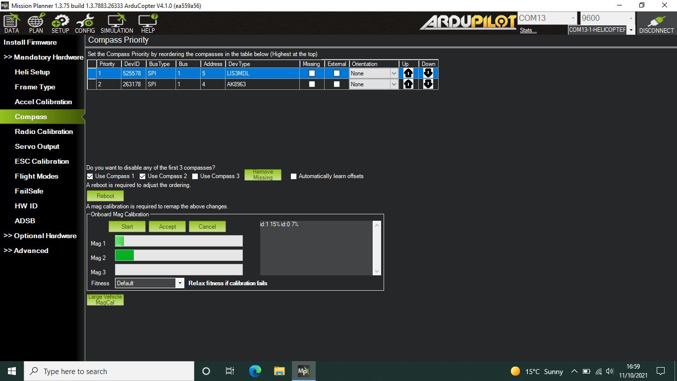
My first query is, the MP screen shows LIS3MDL mag and AK8963 mag; the LIS3MDL is clearly the one on the R15 board, but is the AK8963 the one on the GPS, or is it part of the MPU-9250? MP won’t allow me to check its ‘External’ box.
My second query is, the attached screen shot shows how far calibration got after 30 minutes outdoors away from any magnetism. I don’t remember it taking this long with my Pixhawk 2.4.8. At this rate it’s going to take at least 5 hours to complete (and run down my laptop battery!). Is this normal?
It’s the internal one on the SPI bus. If it’s external it will be either I2C or CAN depending on the module you have. The external mag is not being recognized.
It’s pointless to do compass calibration out of the model. The whole point of the calibration is to learn offsets from on-vehicle local interference.
No. What were you doing with it for 30 minutes? It typically takes a minute or few.
Sometimes if you have interferences on the mags you need more time for perform a good calibration.
Just keep far as much as possible the fc and the gps with mag far from antennas… and Power cables.
Check to rotate the vehicle on all axis… not too fast and not to slow.
Dohhh! Another ‘senior moment’! I’d forgotten the bit about moving it around on all axes! It was just sitting still on my bench.
So, my biggest issue is how do I get it to recognise the IST3806 compass in my GPS module? Or how to check that the IST3806 is actually connected and working.
Never heard of an IST3806. You have this one?
mRo SAM GPS + IST8308 Mag
Is GPS working indicating the module is getting power?
BTW-You will most likely want to disable those 2 internal compass’s when you get the external one working. You will know when you start receiving compass error messages.
Thanks Dave. Doing the calibration correctly, I’ve now got both onboard compasses calibrated within about 30 seconds
So now my problem is how to get Ardupilot to detect the external compass. As you suggest, I mis-read and/or mis-typed, and it is in fact mRo SAM GPS + IST8308 Mag according to my delivery note, although on the board it says “… IST8610”. I’ve tried switching compass auto-detect off and write params, then switching it on again and write params, but still I only get the two onboard compasses shown in my original screenshot. I’ve checked the pinouts of the R15 and the SAM GPS board to make sure the connections line up correctly, and I note that the SAM GPS board has a separate I2C port with “(1.5k pullup on autopilot)”. Should I be using that instead of the plain vanilla SCL and SDA pins (no mention of a pullup) that are in the 6-pin cable that I’m using?
The i2c port on your gps module its only a bridge of the main Uart port of the module… the 6pin connector already have the i2c coz its 5v-sda-scl-tx-rx-gnd, so you don’t need.
just use the 6 pin cable.
Check if powering the vehicle with a battery you recognize the compasses.
in case go in advanced parameters tree in MP and check under compasses the settings internal or external
That’s what I assumed about the 6-pin cable, but the SAM GPS does say that the I2C port is for “1.5k pullup on autopilot”. I’ve had experience of having to install a pullup on another board with iNav, so I was wondering if that’s an issue here. Shouldn’t be, because R15 and GPS are from the same source.
With 5v power supply I still don’t get the GPS compass. COMPASS_ENABLE = 1 and COMPASS_USE, COMPASS_USE2, and COMPASS_USE3 are all 1 too. I can’t see any other COMPASS settings that might affect detection.
From the “what’s included” it looks like there are 3 6-pin cables supplied for GPS/compass modules depending on the module you have. It wouldn’t be the 1st one.
1x MRC0200- Cable [6-Pins JST-GH] to [6-Pins DF13 + 4-Pins DF13], 150mm (Old 3DR GPS with Compass).
1x MRC0206- Cable [6-Pins JST-GH] to [6-Pins JST-GH], 150mm (For latest GPSs).
1x MRC0222- Cable [6-Pins JST-GH] to [6-Pins JST-SH], 150mm (Ready to Fly Quad uBlox M8 GPS).
I have 3 pixracers, no Mro GPS modules, and have not needed pull-up resistors.
Thanks David and Dave. As you say, there are several cables included, several which are exactly the same as each other. The one I’m using is one of the only ones that fits the 6-pin ‘snaplock’ connectors on the R15 and the GPS board, and from the pinout diagrams it looks right. The the GPS is working, so at least +, GND, Rx, and Tx are connected correctly. The only thing I could think of is if the SCL and SDA pins are reversed from what I think the diagrams are showing me, but none of the included cables have those two wires crossed over. I can pull the SCL and SDA pins on one end of the cable and cross them over to see if that works, but I don’t know if that’s going to damage anything if it’s wrong.
As previously said you don’t need add external pull up resistors coz are already on the board.
if you are sure that sda and scl are reversed you can reverse the connection pin of the cable
Yes, I understand about not needing pull up resistors.
I’m not sure the SDA and SCL are reversed, indeed according to the pinout diagrams I’ve got they’re connected correctly. But what I’m wondering is, if I reverse the connection pins to check the possibility that they’re wrong way round, will it do any harm to the R15 or the GPS?
I’ve got a few chores to do around the house before winter sets in, but as soon as I get a chance I plan to (a) swap the two wires just in case that’s the problem, then (b) try another GPS/compass module that I’ve got from an old quadcopter. I’ll have to jury-rig the connections because the plug is different, which is why it’s not the first test
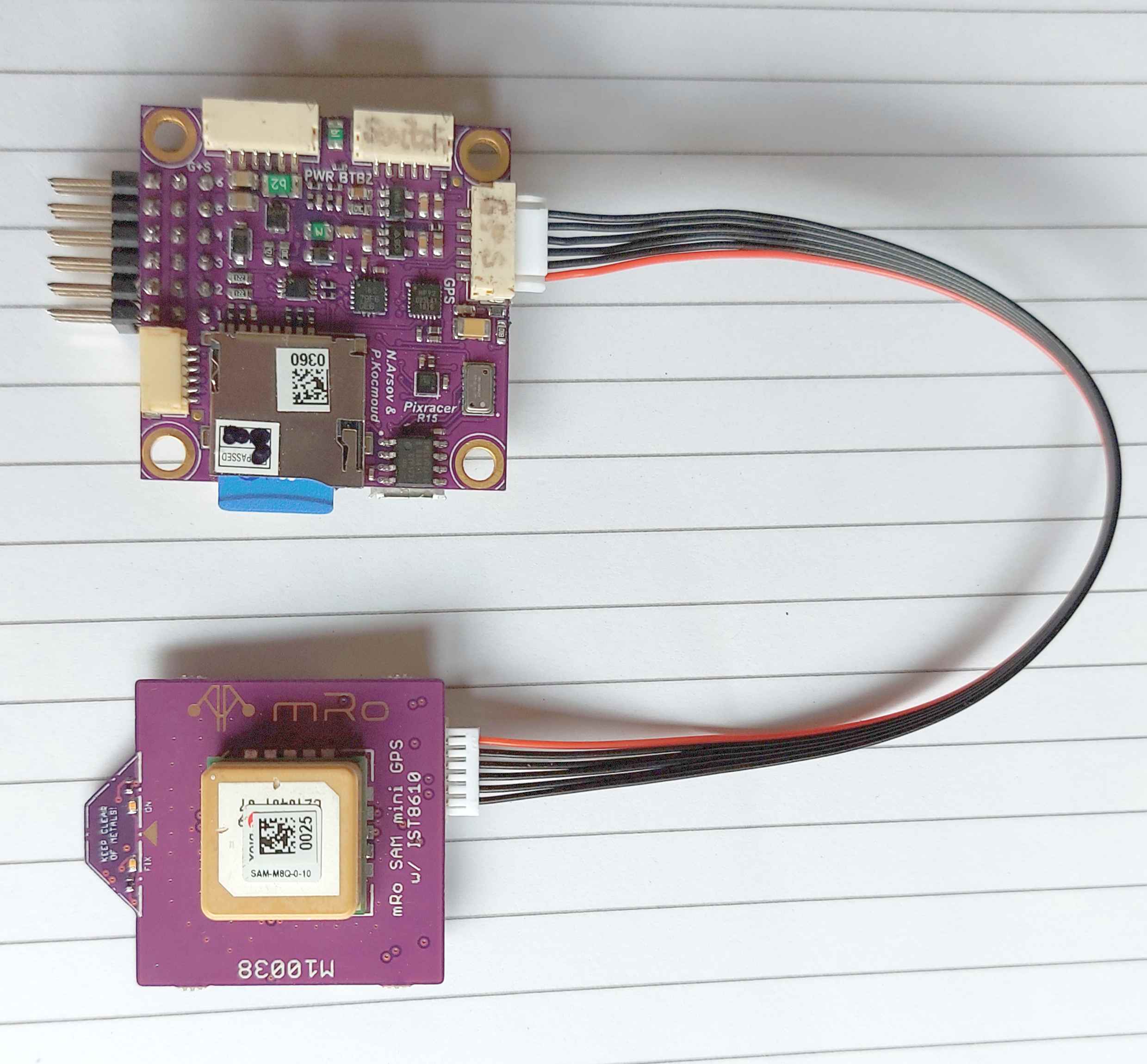
Attached is a photo of my setup with the GPS module connected to the R15. I’ve tried using a different 6-wire cable in case it was faulty, but same result – GPS is working but external compass not detected. Just in case it’s not clear in the photo, none of the wires in the cable are crossed – they’re in the same order at each end.
I’ve come to the conclusion my R15 board is faulty out of the box
I’ve connected the GPS module from my RadioLink Mini Pix (I knew it would be useful for something!) to the R15 board, and MP still doesn’t detect the external compass. But when I connect the mRo SAM GPS to the RadioLink Mini Pix, MP does detect the external compass and shows it as IST8308.
Could there be any explanation other than a faulty R15 board? I’ve contacted mRo with those findings.