Precision GNSS RTK supported Auto Landings

We have been impressed with videos showing the butter smooth landings of the Elanus Duo (Believer frame made by MakeFLyEasy, assembled and configured by DualRC) and decided to choose it as a mapping platform for work in large African cities. Initially we were going to train operators onsite but Covid19 put a rude end to that idea. Instead travel restrictions led to a different approach: Why not equip the platform with precise navigation systems so that precise landings can be safely executed on short runways automatically, thereby reducing or eliminating the need for piloting skills and long runways and hence for onsite training?
In our first tests the manufacturer recommended that final landing approaches should be 300m long from an altitude of 30m resulting in a very flat approach slope of less than 7 degrees. That approach requires runway lengths well in excess of the soccer field sized landing fields that would be available for operations in dense and informal urban environments. We thus had to come up with an approach that required much shorter runways.
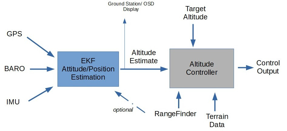
To achieve spatial precision in automated landings we specified a dual frequency GNSS RTK capable receiver for very precise navigation in RTK mode. Accordingly, DualRC installed the uBlox based dual frequency F9P receiver from Drotek. To provide redundancy in accurate height measurements during landing, we installed a TF Mini Plus Lidar sensor to act as rangefinder (altimeter). After some modifications we managed to rapidly get stable RTK fixed solutions near the launch/landing site. (We set up a V-Map receiver to provide reference data in real time via Mavlink.) The maximum range finder range is 12m. Prior to any further experimentation the platforms were weight balanced and tuned.
To experiment with approaches leading to shorter runways we started off by designing a short waypoint program with a landing sequence of which the last leg started off at 200m away from and 60m above (resulting slope of 17 degrees) an accurately (2cm) surveyed touch down point. Our horizontal LAND coordinates were obtained by placing the plane on the desired touch down point while in RTK fixed status. The GNSS RTK derived horizontal “home position” coordinates were entered in the coordinate fields of the LAND point in the waypoint program. This was obviously done prior to writing the waypoint file to the drone.
In all our test flights we followed the following procedure:
• Place drone flat on ground, centered over the desired touch down point.

• Ensure RTK status is fixed.
• Arm the motors.
• Launch in auto mode.
• Complete the entire flight in auto mode.
• Wait for drone to disarm.
• Repeat same procedure for next flight

We understand that the absolute height attached to the desired landing position is determined by the height of the drone at the time the drone is armed. For a robust investigation of landing repeatability it would thus have been necessary to arm the drone on the surveyed touch down position for each and every flight. Since the landing strip we used had a very flat profile, we did not always arm the drone at the touch down spot but rather at the position where the drone came to rest after landing. The maximum vertical difference between touch down position and take-off arming position is, in our estimate, less than 10cm and presumably insignificant from a practical point of view.


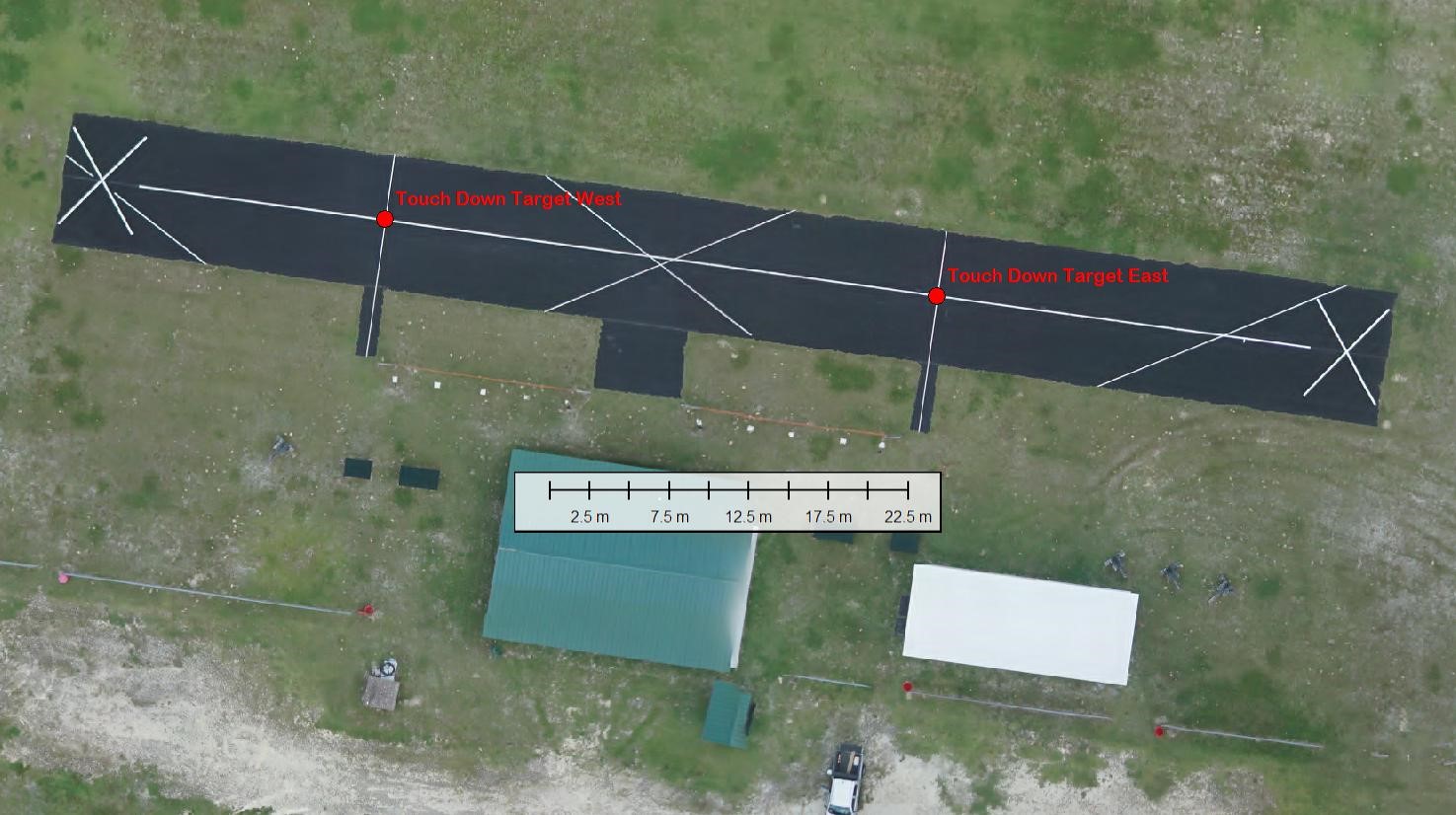
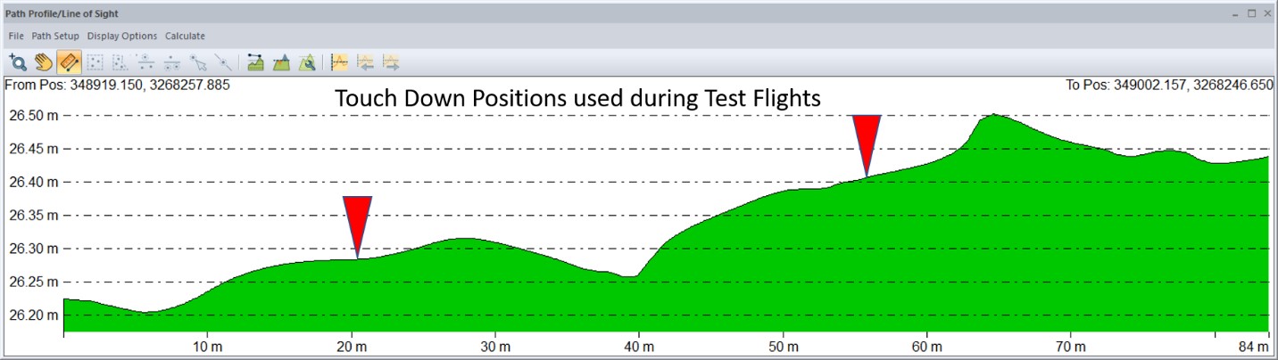
Figure 1:Center Line Profile of the runway used in our experiments.

Following the above procedure we performed 25 flights on 09-09-2020, all in exactly the same manner as described above. All the landings were overshot. The longest distance between desired land position and where the plane came to rest was 26.5m. The lateral distribution of the final trajectories – i.e. between touch down and end-of-skid is 4.5m. Hence, based on the landing trajectories of the 25 test flights one could state that under the given conditions and with the settings in place at the time of the flights, a landing patch of 10mx30m would be sufficient to land the plane safely in automatic mode.


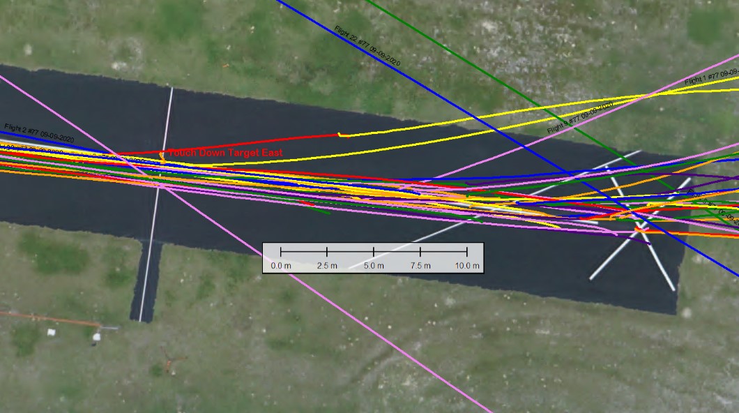
Figure 2: Plan view of 25 test landing trajectories


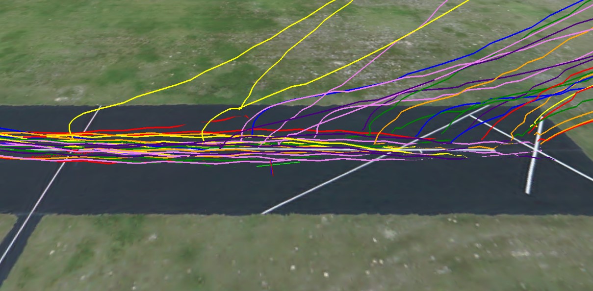
Figure 3: 3D view of 25 test landing trajectories


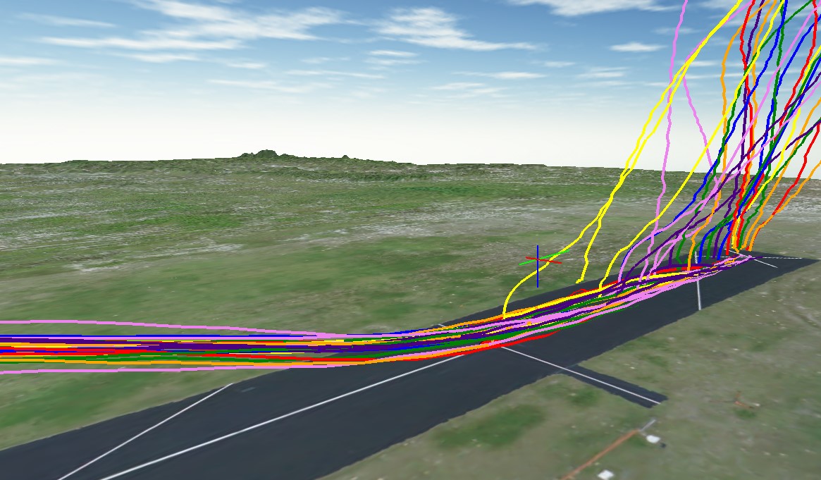
Figure 4: Another 3D view of 25 test landing trajectories

To test the entire mapping system we flew two automatic flights with the same plane on 09-11-2020, this time including aerial image acquisition in the waypoint file. These flights were conducted with the identical payload, weight balancing and parameter settings as during the test flights on 09-0-2020 and to our great disappointment the landings of both the flights fell well beyond the established 10mx30m landing footprint which we thought we had established with the 25 test flights.
For flight 1 the final rest position was 52m beyond the desired touch down point while that for flight 2 was 42m.


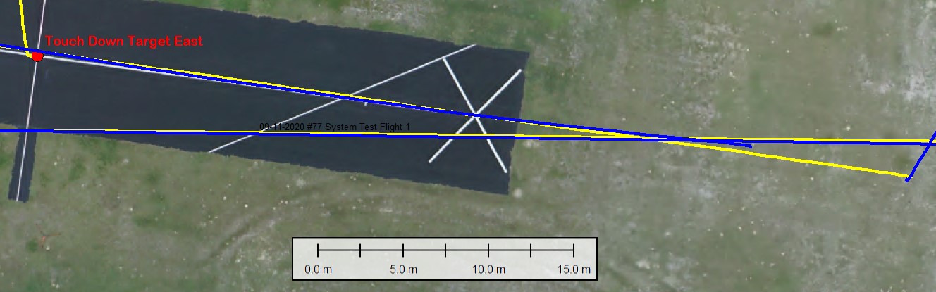
Figure 5: Plan view of system test landings (Flight 1 blue, Flight 2 yellow)


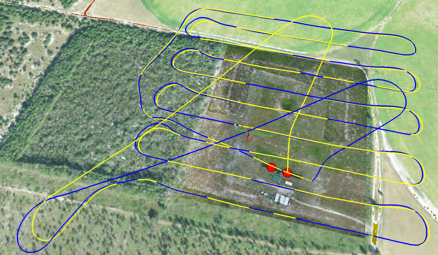
Figure 6: 3D view of two system test flights (Flight 1 blue, Flight 2 yellow)


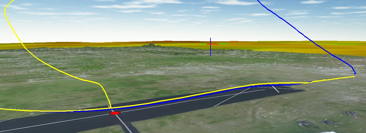
Figure 7: Detailed 3D View of System test landings


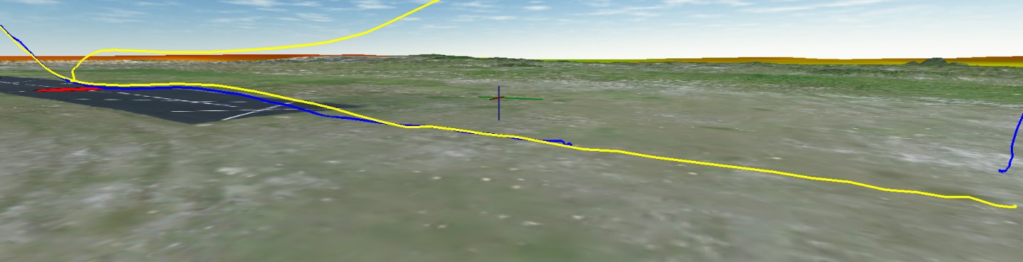
Figure 8: Another detailed 3D View of System test landings

Videos and logs of all the landings can be found here:
https://drive.google.com/drive/folders/1nUr7FypA2kKZzI-_-Hw76K1XY1ko_B1p?usp=sharing
Some observations and notes:

  1. Prior to performing the test landings we experimented MAINLY with the following parameters:
    a. LAND_FLARE_ALT
    b. LAND_FLARE-SEC
    c. LAND_PF_ALT
    d. LAND_PF_ARSPD
    e. RNGFND_LANDING
    f. TECS_LAND_SINK
  2. We consistently overshoot.
  3. RTK fixed mode very stable – hence cm positioning was available during all the landing phases for all the test flights.
  4. Range Finder is rarely utilized/engaged above 2m… settings allow for use of Range Finder as primary height source at 70% of 12m.
    Questions:
    a. Why is there a separation in the procedure to determine horizontal land position coordinates and vertical position? When RTK is fixed the accuracy of a cm is virtually guaranteed and for all practical purposes the same in all three dimensions.
    b. Why can’t one enter an absolute height for the landing position - like entering a latitude and a longitude?
    c. Is it at all possible to land automatically at a position with an elevation that differs significantly from the elevation determined when the platform is armed? If so, what is the recommended procedure?
    d. We are rather impressed by the consistency in the landing precision, but given the high accuracy of the navigational inputs – i.e. RTK fixed (1cm) and lidar range finder (also about 1cm) - why are we not getting touch downs much closer to the landing position? Is the flight controller fully utilizing the high degree of accuracy and the high confidence levels associated with RTK fixed solutions?
6 Likes

I could surely respond to 4a.

With such heavy airplane we expect stall speeds at high alphas in the range of 12-15m/s I be seen duos to stall at 18m/s.

Your GPS refresh rate is 5hz and your RTK refresh rate is 1 or 2 Hz, thus even in perfect world scenario and with the best class reception with your flying speed you could be moved up to 10meters!! Between measurements, or 5 at best.

Now given the fact that EKF blends all this info with your IMU it may fix things, but if you were a dev, most probably you would choose the higher refresh rate that a lidar can offer.

Also RTK may offer cm accuracies, but the aircraft still doesn’t know the terrain alt at any desired landing point you may choose, while lidar does.

Regarding 4d.
I have found that in order to consistently make precision landings you either have to tune your tecs to the edge(along with the params you mentioned) or just fix your landing patterns to meet your aircraft/tecs potentials. I.e. if you overshoot 25m then just prolong your waypoint before landing 25m or slightly decrease the altitude until you make it touch down on your target.

A! 4b. You can if you fly at absolute altitudes
4c. Check my lidar and previous comment

Overall bravo!! very determined and detailed experiment. Thanks for the write-up.

Best,
Dimitris

In case you are asking this in order to have a fixed landing coordinate at which you can always set your landing, I think this isn’t going to work:

Unless I’m wrong, RTK GPS will give you cm-level position solution relative to your base-station, not to the geoid itself. So from day-to-day your initialization coordinates (and height, of course) might differ slightly.
Unless of course you input your base-station coordinates yourself or let it settle on a very precise fix over a long time (more than half an hour). How this works depends on the GPS module itself.

P.S. Hi @Dimitris_Stefanakis

The Septentrio Altus NR2 RTK basestation corrects it`s own position using NTRIP. So the geoid position is accurate to about a couple of cm. And that is then passed on to the rover RTK GPS, effectively making it also very accurate relative to the geoid. You should get something from 3 to 20cm depending on the distance to the NTRIP server antenna.

Please do not forget that the horizontal RTK accuracy relative to base station is topically 1 to 4 cm. but the vertical accuracy is about 3 times worse.

like @proficnc explains bellow RTCM rate has (almost) nothing to do with GPS refresh rate. The septentrio rover delivers 10Hz updates, regardless of RTCM rate.

Guys, as I mentioned, it’s not about absolute accuracy only. It’s about actual and usable refresh rate of any accuracy, meaning RTK at base rover configuration is 2hz ( except if you afford to buy two septentrios at 50Hz!!) Or with NTRIP you have GPS at L1/L2 usually at 2hz and GNSS at 1hz mostly at L1 plus the telemetry latency. Which rounds at 1Hz.

So even if you fly a bixler your best bet is within 5m, relying on RTK. A viable solution could be a PAPI light like beacon and a camera.

P.S. hi George :grin:

The RTCM update rate is not directly related to position accuracy, the rtcm messages tell the RTK gps what corrections need to be done, this is not something that changes fast, so base station updates need only be at 1 hz

Yes, the GPS will give position at 5Hz, but then the EKF consumes that an interpolates the mid stream position.

There are other factors at play other than the absolute position however.

The point about a lidar for final flare is valid though, as this gives true height above terrain

2 Likes

Hi Dimitris_Stefanakis, thank you for your response. We thought about this issue with GPS hz rate and have since increased the rate to 10hz which gives us a position update roughly every 1.3m during landing. We also incorporated the use of Lidar at 1khz to more accurately determine height. As you can see from the logs, there is room for improvement for precision landing, especially with the rich and accurate data we are getting from the sensors

So, if you zeroed out any sensor issues and your EKF is fed with excellent data as most mentioned above, then for sure you must give more weight to your physical aspect of landing. ie the landing pattern vs the flight envelope.

As you mentioned in the beginning, vendor proposed 300m long and 30m Alt for last waypoint @ 7 degrees slope, whereas your test went up to 17 degrees!!

I wouldn’t like to mess you with the aerodynamics, but in short, its very difficult to flare and de-accelerate a DUO that gains speed at -17d. I have a hunch that 12d should do the job more consistently

Best,
Dimitris

1 Like

We are pushing RTK fixed solution quality NMEA at 10Hz plus we provide 800Hz lidar for altitude. Since we will be operating in remote areas with no or limited access to the internet we will always be using our own base station.
For the case where take-off and landing are in the same location you can use standalone (approximate) coordinates for the base - as long as you don’t change the base position or coordinates in the time between take-off and landing. In this case you don’t require absolute positioning and heighting of the land position. If however you want to land at a location different from the take-off you must make sure that the coordinates of the base station are on the same reference frame as the coordinates of the landing position.
We are still hoping that the use of 10Hz RTK and lidar altitude inputs together with reverse thrust will give us a safe automatic runway length for automatic landings of some 10m. Do you think this is at all a reasonable expectation?

Why not trying in SITL, you will know really how it works in simulation area. Play with EKF : disable EKF to test.

GPS, Baro and IMU affect altitude :


Source : https://ardupilot.org/plane/docs/common-understanding-altitude.html

Play with EK2_ALT_SOURCE:

Value Meaning
0 Use Baro
1 Use Range Finder
2 Use GPS
3 Use Range Beacon

https://ardupilot.org/plane/docs/parameters.html#ek2-alt-source-primary-altitude-sensor-source in combination with https://ardupilot.org/plane/docs/parameters.html#ek2-rng-use-hgt-range-finder-switch-height-percentage as mentionned.

Play with EK3_ALT_SOURCE:

Value Meaning
0 Use Baro
1 Use Range Finder
2 Use GPS
3 Use Range Beacon
4 Use External Nav

https://ardupilot.org/plane/docs/parameters.html#ek3-alt-source-primary-altitude-sensor-source

Play with some parameters and TECS :

  • LAND _FLARE_ALT
  • LAND _PITCH_CD
  • LIM_PITCH_MIN
  • NAVL1_PERIOD
  • TECS_SINK_MIN
  • TECS_SINK_MAX

Thanks for the good advice Sylvain.

One more question: Does GNSS RTK improve precision in automatic landings or not?

Just one more input: you put a survey grade gnss but forgot that you still have a less precise inertial sensor onboard. I didn’t test but I’m thinking that a survey grade INS like vn200 or other in combination to a survey grade GNSS could improve situation …