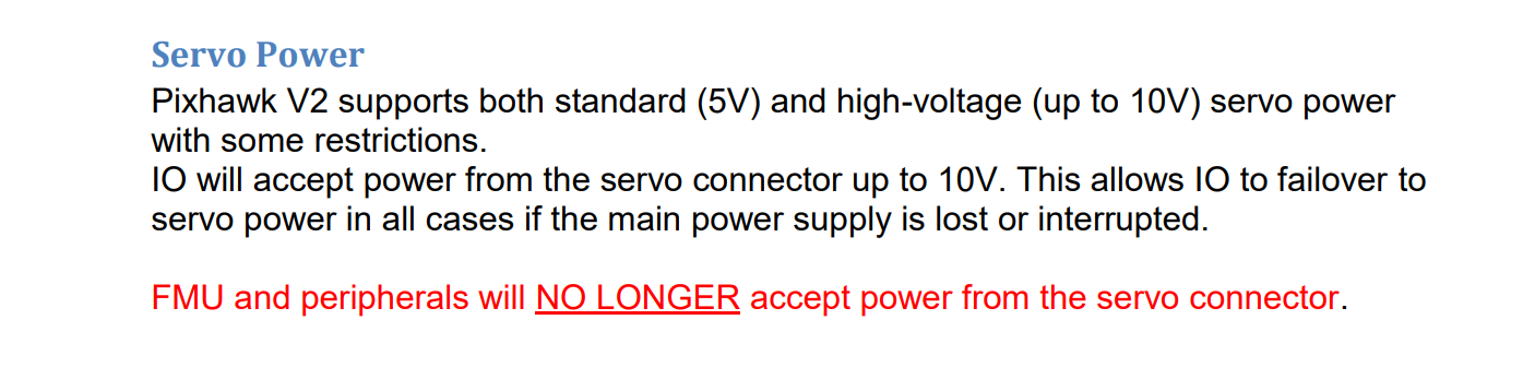
Hi everyone. I am a novice RC member whom is doing a university project that might use a flight controller to actuate high voltage digital servos. It is part of a ducted fan rocket. The servos : https://hitecrcd.com/products/servos/digital/coreless/hs-7235mh/product ideally would work with 6v-7.4v. They are part of a thrust vectoring mechanism whose actuation is governed by a Pixhawk flight controller: Pixhawk px4 2.4.8 flight controller 32 bit arm px4fmu px4io combo for rc drone fpv racing Sale - Banggood.com sold out-arrival notice-arrival notice . We intend on using a 6s Lipo battery to power the components. I would like to confirm if this flight controller is capable of handling up to 7.4V to these servos (the stall current is 1.6A). I had seen in a documentation that the pixhawk can handle up to 10V, as seen in the image . I would like to confirm if this is true, as I am not 100% if servo power refers to this. Additionally, I would like to know if anyone has successfully attempted such a setup.
Not a pixhawk dev, but … This seems to be for the power rail, you don’t have to give juice to your servos through the power rail, directly connect them to your 6-7.4v output if you have any doubts.
There are a lot of misconception on the power rail, please look up what it is. Basicaly, all the + pin are bridged together but not connected to anything (this was not exactly the case on mine, so be careful), this way you input the voltage/power you want on the rail, and it will not disturb the flight controller that should use a second power unit for stability reason.
The PWM pins (relative to the ground pins) are the ones that are connected to your Pixhawk.
Hi 2lian, cool to hear of you again! Yes you are right. From checking a video by painless 360 ( Common PixHawk Setup Problems and How to Avoid Them) and through the wiki it seems only the receiver channel is powered through the Rcin in those rails.
I was quite confused about it. But it seems like its as you mentioned earlier. Something along needing a separate BEC for powering the servos first from a source, then them connecting to the power rails. Im still looking for aa proper circuit of it being done
Make sure you watch the section about power distribution in this video. The power distribution part starts at 5:59.
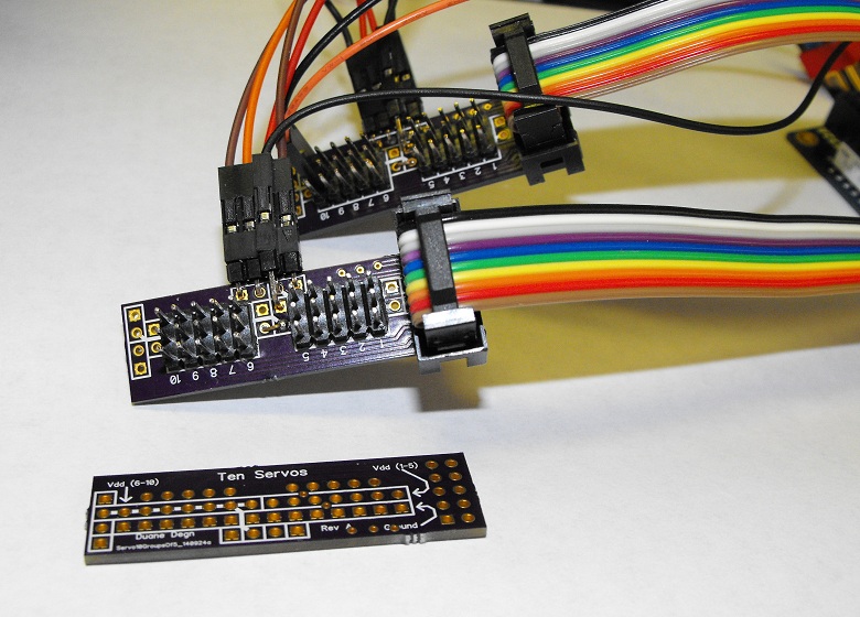
I don’t know what sort of power distribution boards are available for this sort of stuff but I’ve made a few of my own power distribution boards for my robots. Here’s one design which excludes the solder mask on the bottom of the power line of the PCB. This lets you add a layer of solder to allow even more current to flow without heating up the board.
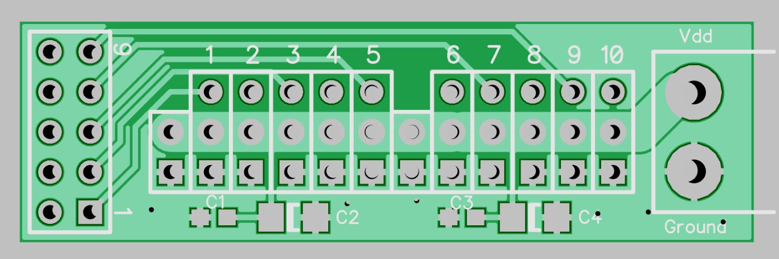
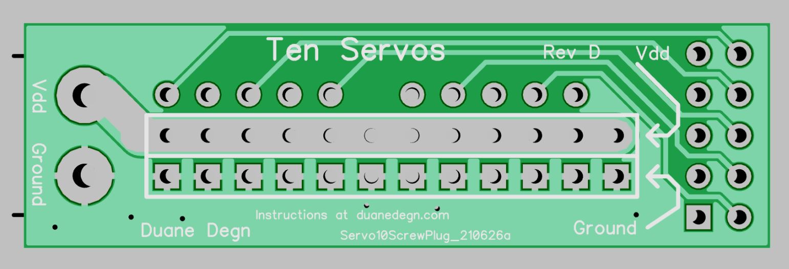
The signal lines can connect to the 2x5 header on the left (looking from the top) I often use ribbon cable to make this connection.
Here’s a link to the zipped Gerber files for the board above. If you submit this zip file to OSHPark, they’ll make you a set of 3 for $5.
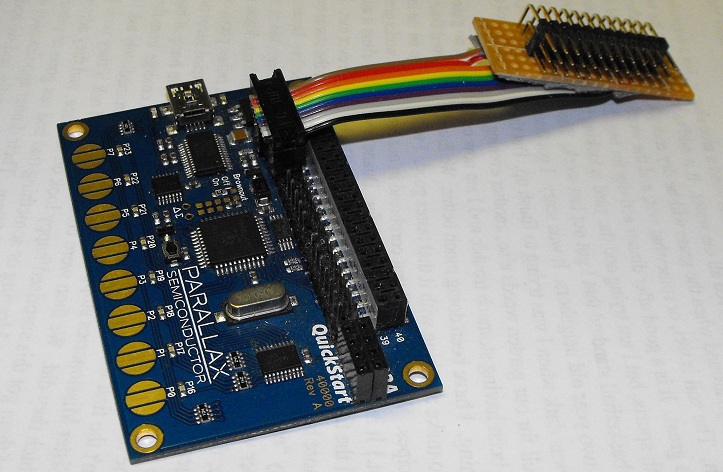
Here’s a photo of an older servo power board I made.
While I used a ribbon cable in this situation, I often just use separate wires as well.
These sorts of boards are easy to DIY using some perf board. Here’s an earlier version made from perf board.
I’m new to all things Pixhawk so there may be plenty of other solutions which I am not aware. I just thought I’d share some of my experiences using lots of servos.
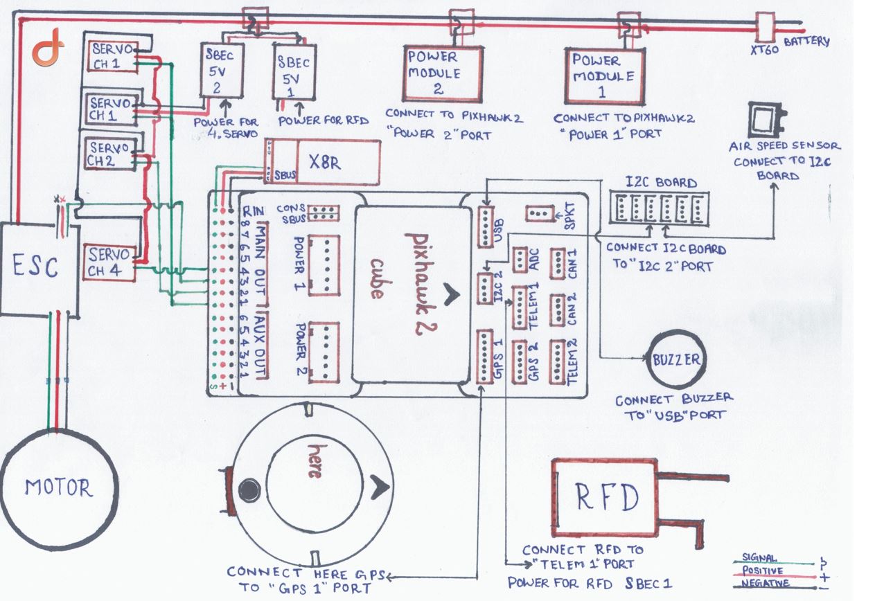
Hi Ddegn. Thank you for sharing your power distrubution board designs and for the link! That video did provide alot of clarity surrounding the servo rail and inputs required. In addition, I had came across a schematic done by another person that may be of use for anyone in a similar situation.
. I believe this method is as was mentioned in the video you sent.