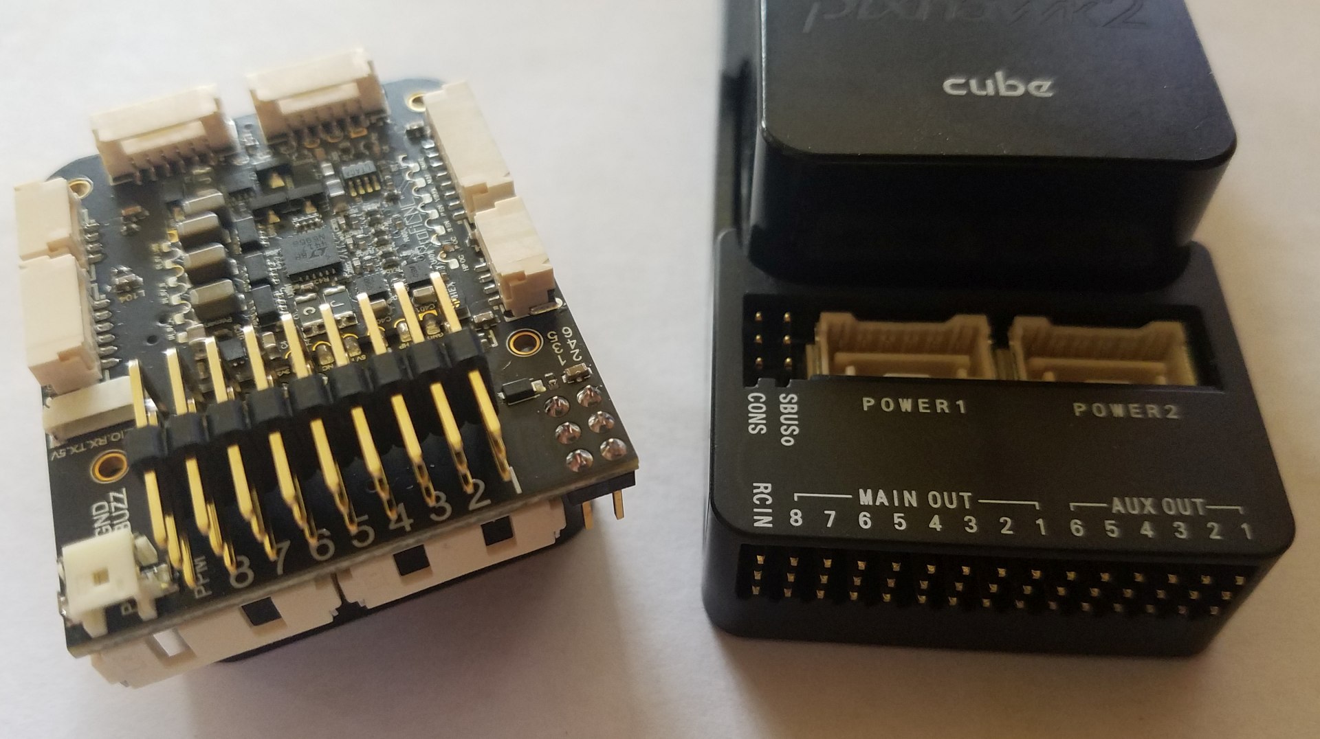
Just recieved my PixHawk 2.1 cube mini carrier board today, I haven’t put this build together yet but I am looking at the connections and I don’t see any connection for my Spektrum RC receiver on the mini carrier board. the standard “full size” board has an RC IN port, but this mini carrier has nothing like that at all.
where does the RC receiver plug into?
also, I do not currently have a telemetry radio for this build, I need to order one. What should i buy? and also, can I fly without it if I’m flying with my DX9 in a GPS assisted mode such as Loiter mode?
I just want to be able to fly and see how long my battery lasts currently.
you plug receivers into the ppm pins at the opposite end to were you plug your esc’s in check the voltage.Regarding telemetry it aint required but is a nice thing to have https://www.3dxr.co.uk/?s=telemetry
Interesting.
I am going to be asked to install one of these mini carriers soon and your post prompted me to go digging for the documentation in preparation.
I could not find any docs on these boards???
Does anyone know of ANY documents?
Or is the screen printing on the board all we get?
As per all ProfiCNC boards… the Facebook forum is where I am, and the best place to ask any questions etc.
This board is a developer pre-release board… unfortunately that little tip got missed at release, and so it’s out in the wild a bit early…
The wiki is a community effort, it always has been, and always will be. That’s why things are so cheap! If we had to have technical writers and wiki maintainers on staff to do that, then prices would be higher, and we couldn’t do prerelease batches like this.
So… I will answer any questions you guys have… but in return, I expect that you guys will update the wiki at ardupilot.org… its publicably editable.
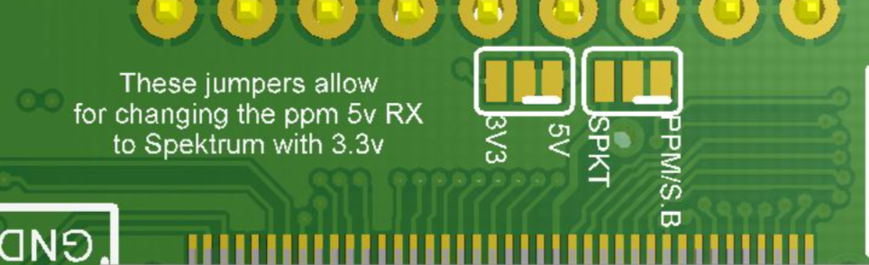
Yes, it has Spektrum RC in…
If you look on the cube side of the board, you will see two jumpers…
I talked to ProfiCNC on Facebook, the pins on the mini carrier board are the same as the larger or standard sized board. The bottom pins are signal, Middle is 5v, and top pins are ground.
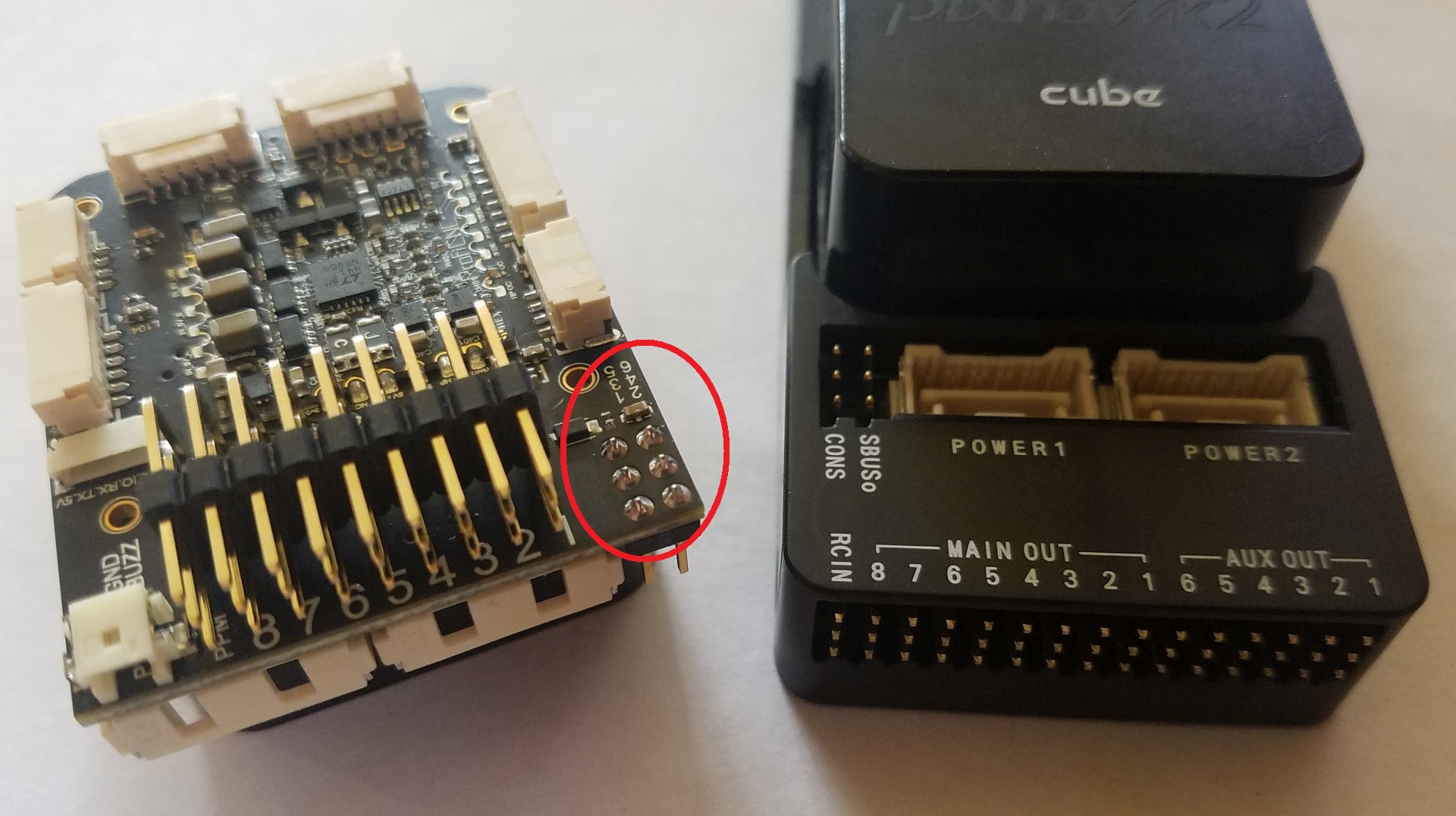
if you can find a pinout of the standard carrier board, you should be able to reference the numbers from it. I’m not near my drone right now but when I get back I’ll take a pic for you.
Can you please provide some form of schematic for the Mini carrier board? I’m sure that you guys had to provide a schematic to have them produced in China.
The pinout is not the same as the standard board actually, the top and bottom rails on the mini are flipped from the standard carrier board. I’m not at my drone currently but if I remember correctly, the top rail on the standard board is ground, middle is 5v, and bottom rail is signal.
On the mini board the top rail is signal, middle is 5v, bottom rail is ground (this is just from my memory so I could have it mixed up truthfully) but the top and bottom rails are definitely flipped on the boards.