no, don‘t connect anything above 3.3V to your MCU directly!
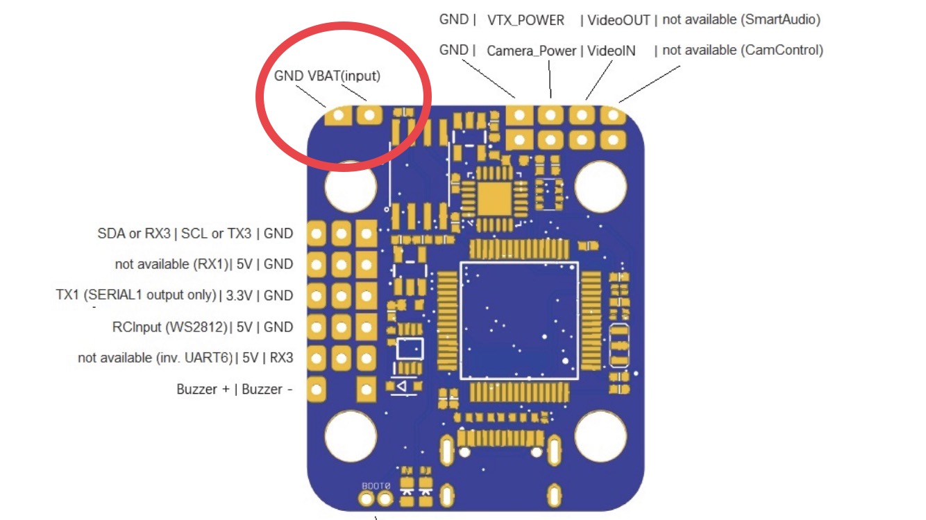
what i meant was to use the dedicated pads to connect your battery as a place to start from:
Yes, I supposed the same. VBAT gets the direct voltage from battery but it does not work. It seems I have defective board unfortunately. Thank you for your help.
so if you
- reset all your parameters to default
- reboot
- set BATT_MON = 3
- reboot
- connect your flight battery to the batt pads
what batt voltage does MP show (and what is your actual batt voltage)?
I have done that you proposed. In addition I disconnect the 4in1 ESC from FC just to be sure. In this case the battery voltage monitoring works. I did a debugging and it turned out the battery voltage monitoring works only if the current PIN is not connected from ESC to FC. I am using the following ESC: https://www.aliexpress.com/item/32845314114.html
The socket pins are not identical I took it into account. So the ESC current pin goes to CURRENT_SOCKET PC2 pin directly. The ESC current pin provides 7mV in idle state and if motors rotating on 20% throttle the current pin provides 110mV. I guess this signal should fit for MCU, shouldn’t it?
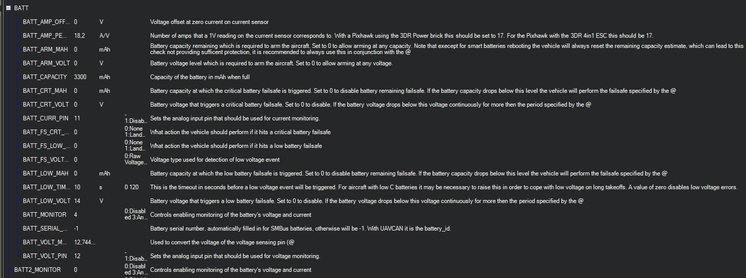
So if this pin is connected the battery voltage monitoring shows 0,2V instead of ~16V. The BATT_MON value does not matter (3, 4). Parameters are the following:
So it can be problem with the firmware? I don’t understand why the battery voltage monitor does not work if Current pin is conencted between ESC anf FC.
imho you need to recheck those socket pins are matching, which is not excatly facilitated by the different socket pin-maps provided on V6.1 and V6.2 revision.
PC2 (PIN12) by hardware def is used as VOLTAGE pin, not current
PC1 ( PIN11) is the CURRENT pin.
This diagram was shared by Ari Krupnik on 23th August:
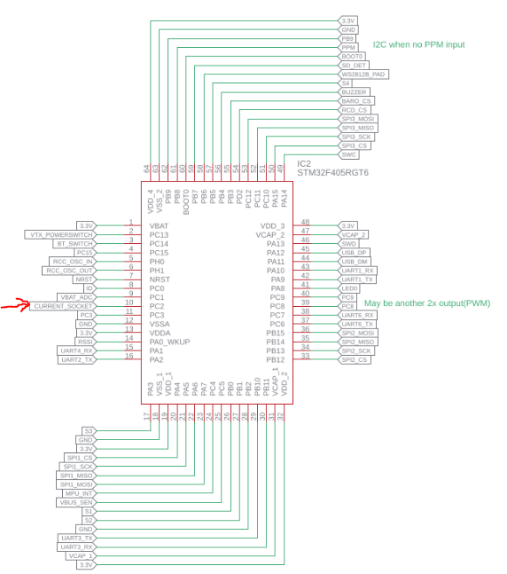
I’ve got the ESC current signal on the pin I highlighted with red arrow (CURRENT_SOCKET [PC2]) I measured it. Is this pin defined as PIN 11 in AP? Voltage monitoring works with PIN 12 settings.
see hardware pin to adc_chan (= runtime pin no) table:
Thanks for the table it helped a lot. Based on the diagram that Ari shared with us we can see in case of STM32F405RGT6 the current pin is PC2, the voltage pin is PC1. In the table you provided the PC1 is pin 11 and PC2 is pin 12. So at the end the default pin for V6.1 board (voltage: 12, current: 11) is not correct. It needs to be exchanged to voltage: 11 and current 12.
My observiations:
- Test with voltage - Pin 12, current - Pin 11: Voltage monitoring is working only if the current signal cable is completely not connected to the board. In this case there is no current monitoring.
- Test with voltage - Pin 11, current - Pin 12: It is working well even if the current signal is connected to the board -> current and voltage monitoring available.
The solution is to exchange the default pins for voltage and current monitoring in case of V6.1. I don’t know why it should be but maybe the V6 has different MCU and not STM32F405RGT6. (I’m not sure.)
Has anyone tried the voltage and current monitoring using onboard voltage sensor and current pin with V6.1 board?
I received this diagram from an employee of the vendor. There is no guarantee that it is correct to the board you have. The vendor may have made changes to the board, or the schematic, or both, between when the board went to fab and when I received the schematic.
Ari.
Yes, I use both Voltage and current monitoring working well on V6.1. The hwdef file is correct. The vendors’s diagram seems to have been more of a planning document and is not correct for V6 or V6.1 in this respect.
Current pin should be set to 11, Volt to 12. After calibrating both current (via total consumption measured during charge) and voltage, I have voltage multiplier set to 11.775 (voltage divider resistors vary in accuracy from board to board) and amps/volt set to 38 with offset of -0.013 (both of these numbers vary by ESC design.
Note that getting the current reading setup to be accurate both while flying and on the ground may take a few tests. Some current measurement hardware is not completely consistent as the voltage changes and at low currents it may not be very linear.
–Brad
Maybe the diagram is not valid for all V6.1 boards but that helped me out in this topic. I’ve got the board on 17th June so it was the first pack of the new version that’s why it differs to newer ones maybe. With initial calibration I’ve got 11,18 for voltage multiplier and 33,63 for A/V but I used pin 11 for current and pin 12 for voltage.
Anyway thanks all of you who helped me in this investigation. I appreciate it. 
imho it is safe to say that pin definitions and default voltage divider set in hwdef works on all board revisions.
afaik it’s not so safe with the 4-1 socket pinout. i’ve at least seen two diverging 4in1 socket pinout mappings, which is kind of criticial as it involves VBat which will easily fry your board if connected to anything other than the board’s designated ADC.
i’ve updated the board wiki’s pinmap images respectively and added a note to double check.
Hello Guys,
I would need your help again. I would like to use sonar sensor on my drone only for inside purposes. I have HC-SR04 sonar that requires GPIO pins. Is there any possibility to use this sonar on TX3 and RX3?
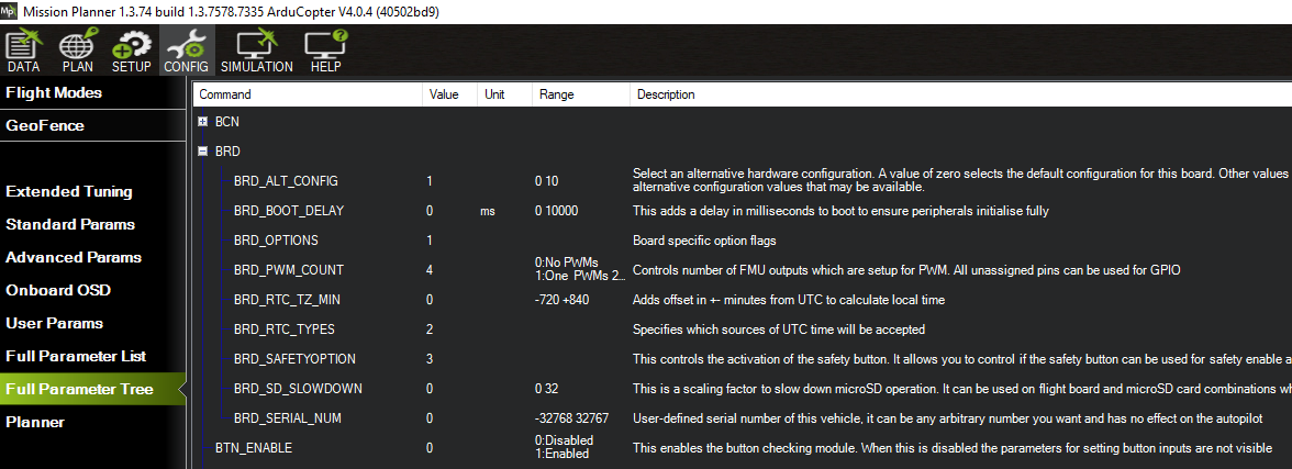
I will set BRD_ALT_CONFIG = 1 to use I2C and SERIAL3 for GPS/compass combo is on PPM (=SCL), PB9 (=SDA), RX6 and TX6 pads.
I know in this case TX3 and RX3 will be SERIAL4 but as far as I know I can change the code and build my own firmware. So my question is that is it possible to set those pins to GPIO pins and set the corresponding pins for parameters: RNGFND1_STOP_PIN and RNGFND1_PIN?
Thank you for your help in advance.
I would have another question.
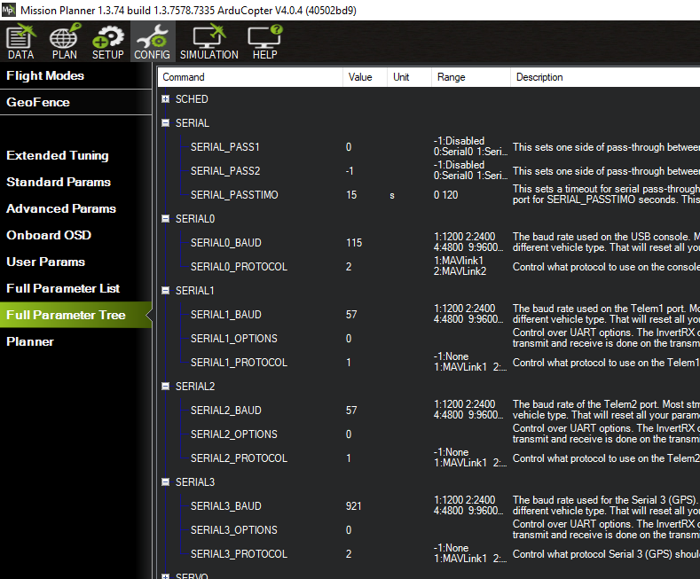
When I set BRD_ALT_CONFIG = 1 then RX3/TX3 would be SERIAL4. Even after rebooting I could not find the correspoding parameters (SERIAL4_) in Mission Planner. I searched for it on AP wiki but did not find anything. What should I set to get SERIAL4_ parameters in Mission Planner?
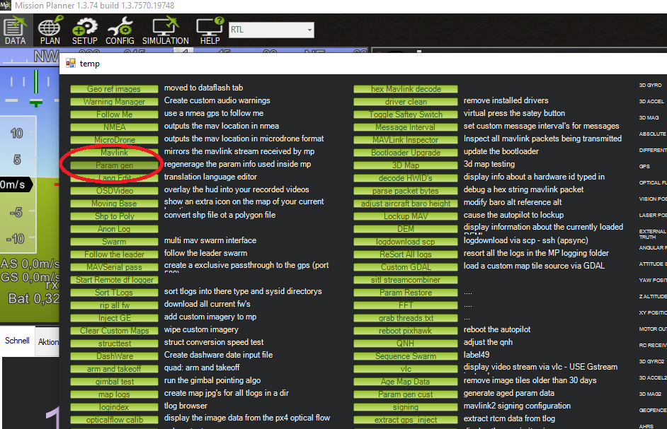
make sure you’re using an up to date MP version. alternatively, try hitting CTRL+F, then click the “param gen” button to regenerate the currently used firmware’s parameters inside MP:
Thanks for your reply but unfortunately it does not help. I removed and installed newest beta version of Mission Planner. I erased the chip and reflashed bootloader from here: https://firmware.ardupilot.org/Tools/Bootloaders/OmnibusNanoV6_bl.bin
and firmware from here:
https://firmware.ardupilot.org/Copter/stable-4.0.4/OmnibusNanoV6/arducopter.apj
I made a ‘Param gen’ on it after setting BRD_ALT_CONFIG to 1 but it does not work. With reboot it is not working as well. I can not find SERIAL4 params.
Do you have any suggestion? Maybe I missed something?
i see you‘re using copter stable 4.04. as for now, you‘ll find that alt config option in latest (master) firmware only.
Okay, I see. I thought that your changes is included in the most recent (4.0.4) stable version since your PR is merged before the new version is announced but I was wrong. Next time I will check it on git directly. Thank you for your help.
Hi all, I have a R1 + plus jumper and I would like to use yaapu script with FC omnibus F4 nano V6.0. I need the S.port and therefore with F4 a non-inverting pad on the rx. I connected the SERIALI 1 of the FC but I cannot read the telemetry on S.port. On the RX I have not updated the FW.
The question is:
on nano V6.0 is it correct to connect S.port to SERIAL 1 pad TX1 on nano v6.0?
Thanks
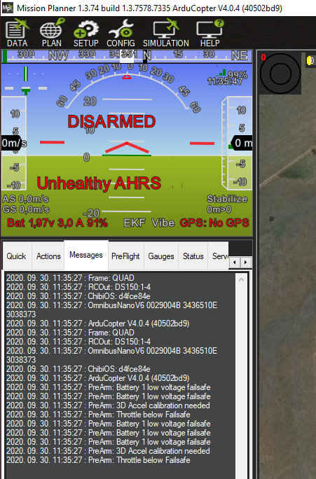
First post here.
MP 1.3.74 with ArduPlane v4.0.7 on Omnibus F4 nano v6.2
BRD_ALT_CONFIG = 1, but no SERIAL4 ??
What I am missing?
br