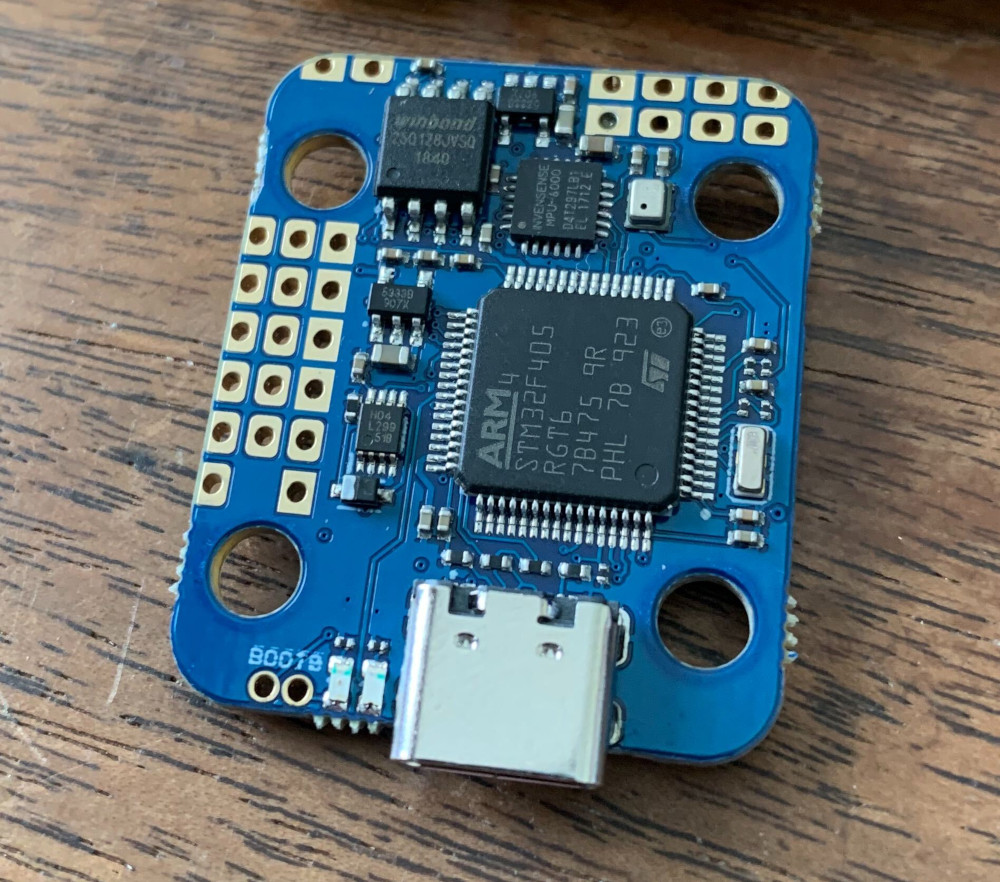
We were able to flash AP bootloaders on them with dfu-util, and install ArduCopter on them. We’ve run into some difficulty finding where the different serial ports come out, and Google turns up surprisingly little. (There are many threads about similar boards from the same vendor, but with different pinouts).
Who is selling them without pinout documentation? The one from getfpv.com is not completely accurate anyway. So far I’ve only confirmed power and ground pads but I’ve already found errors.
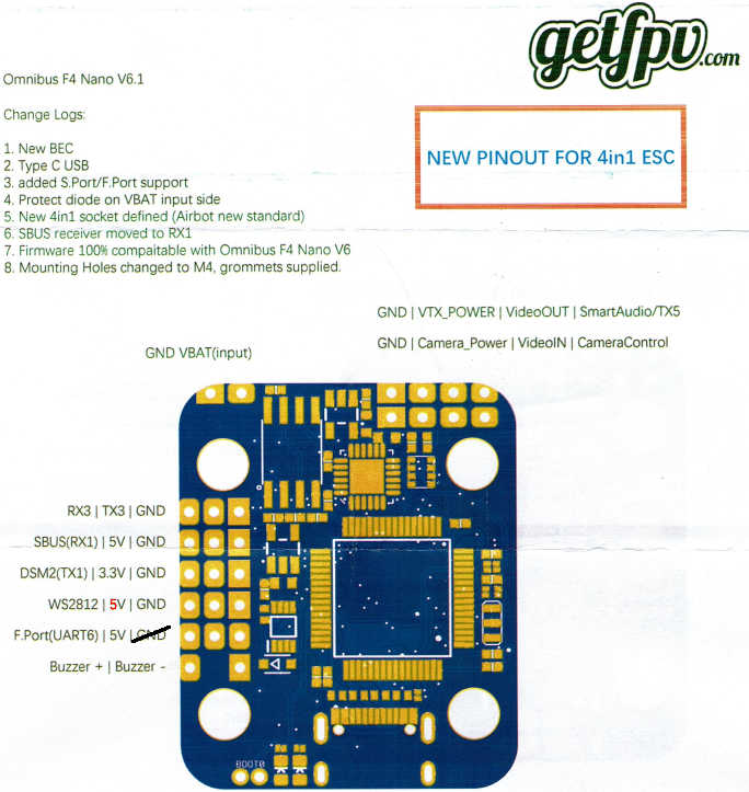
Note that the 5v in red seems to be the BEC while the others seem to be the normal 5V supply.
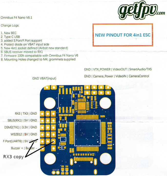
The pin marked GND near the F.Port pin is not a ground pin. It seems to be a driver, perhaps inverted TX6?
The Version 6 board had two 5 V supplies, one labeled 5V, and one higher current supply labeled 5VDC which, I believe was a separate 2A supply. The one I colored red is slightly higher voltage than the rest of the 5V pins so I think it is the separate supply.
Also, that pin is not supplied when powered only from USB
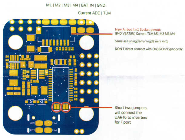
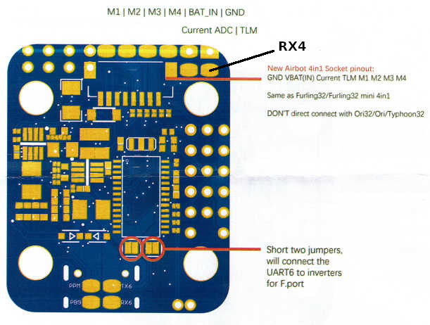
No, but the vendor confirmed that the documentation is wrong and they are updating it. They also pointed out that RX4 is one of the pins on the ESC connector and breaks out to a pad.
Yes, I noticed that as well. The Ardupilot hwdef.dat for the V6 board also documents ESC sensor as UART4_RX. It’s a nice layout in that it provides access to the pads for the current sensor and ESC telemetry pins even if you use the connector instead of the motor PWM pads.
So my problem is that I want two full serial ports, 9ne for GPS and one for telemetry radio. I have UART6 on the back that I can use for either, but I need another one. RX3/TX3 in the top row go to I2C for compass, so can’t use that.
@vierfuffzig, As long as you are adding flexibility, it would be nice to have GPIO or PWM(5) and PWM(6) on PB9 (CAM_C pad) and PA2 (Smart Audio pad) as well. I use these pins on one of my V6 builds for a Firefly 4K split camera which can be controlled by two relay (logic) signals, but I think this board could support a hexa frame as well.
Speaking of alternate use, I don’t use the LED pad (PB6) for anything since I use a TBS CF receiver and combine Telemetry and RC control on RX/TX1. May as well allow the original purpose of GPIO here too. I haven’t checked if this pin could be used for anything else.
The WS2812 pad goes directly to an STM32 pin where one of the alternative functions is USART1_RX. I can’t remember the pin number, I can check when I get home. The pin marked SBUS(RX1) does not connect directly to an STM32 pin. It may be going through a buffer or inverter.
i‘m not 100% positive about the alt() config system working for repurposing pins as PWM as well. this was mentioned on discord recently and afaik it isn‘t featured yet. for now you‘d likely have to build an individualized fw.
if you don‘t need I2C, you might use RCIn via UART to free the LED pin for alternative timer use. that being said, i haven‘t taken a closer look at the F405’s alt functions chart respectively…