I would like to thank you very much everyone who helped in this thread. I’ve successfully configured nano v6.1 because of you. I used arduplane with MSP (DJI FPV) and added changes from this thread. TBS nano rx is connected to the led port, GPS to uart6 and dji air unit is connected to uart3. Everything is working fine.
There is no possibility to make one more uart fully working, right ? I would like to connect crossfire nano rx via csrf or mavlink to get telemetry.
@Mariusz_Labedzki i‘m not familiar with dji MSP implementation. as far as the documents suggest, the V6.x smartaudio pin utilizes PC12 as UART5_TX. if you can run your dji unit from a TX pin only, it might be an option to add that and use USART3 for bidir crsf instead.
as for now i don‘t see hardware options for a third full UART. hoping for more insight and testing once my board arrives.
@Mariusz_Labedzki please forget and forgive what i wrote about PC12. while board specs claim “TX5” on smart audio pad and PC12 is the only pin with that function, it is already used as SPI3_MOSI on OSD chip. so it’s surely not TX5 on that pad. i couldn’t find a way to utilize any further pads.
we “should” have PA2 as USART2_TX on smart audio pad, but i could neither trace that pad back to the PA2 pin or make it work as USART2_TX.
additionally, while Cam_control pad should be on PB7, i couldn’t get that to work as an alternative USART1_RX.
@vierfuffzig thanks for you work on this, I think 2 uarts + sbus is ok for me Im ok to not have telemetry on this plane, good thing is gps + dji fpv is working and thank you guys for that
and I checked dji fpv cannot work with only TX pad, looks like it require 2 way communication. I wish that crossfire protocol can work on one wire like frsky fport.
great you got it working mariusz. i got in contact with airbot and asked for more detail on pin layout. i don’t really expect too much new information though…
Hi Im using 01.00.06.00 But let me check again, maybe I did something wrong. I got OSD on screen but with “0” as the values, for example for battery voltage etc…
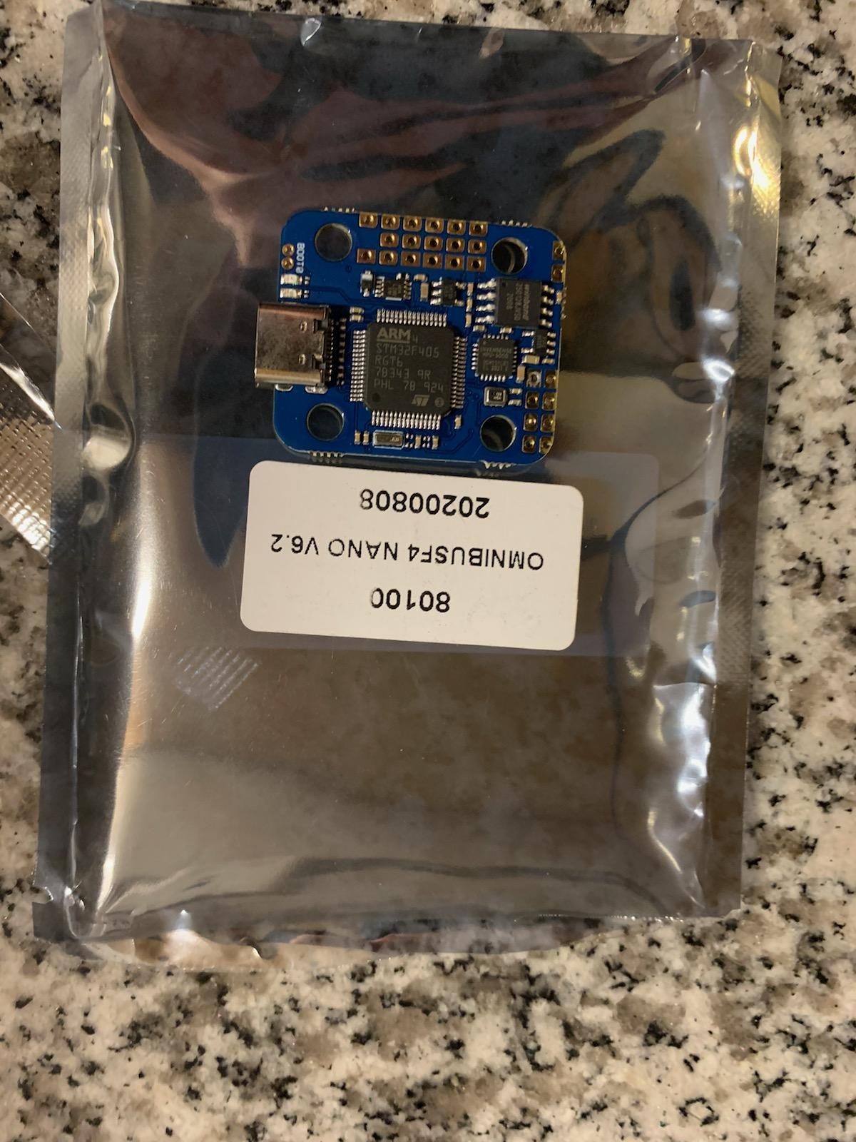
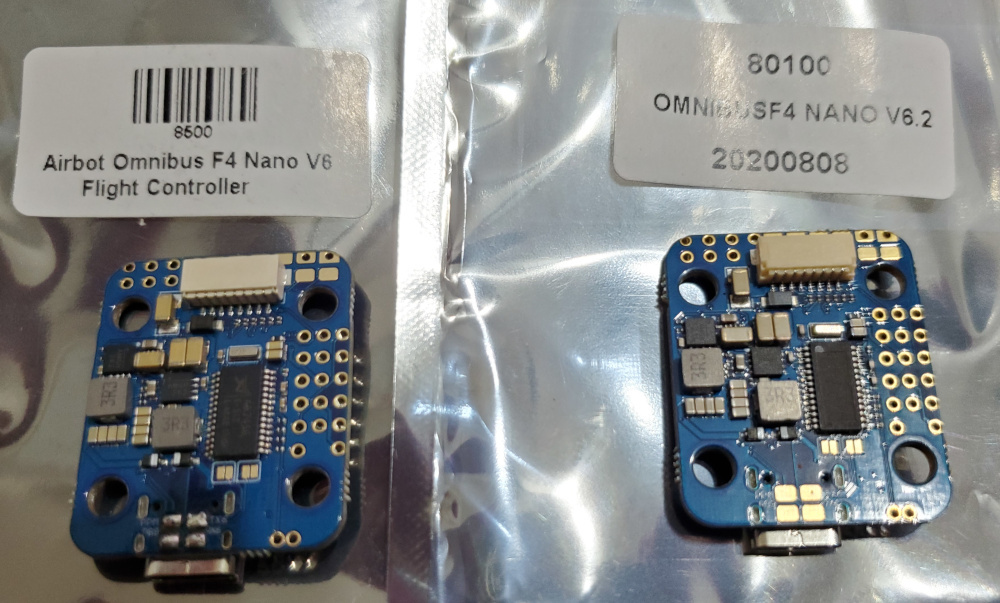
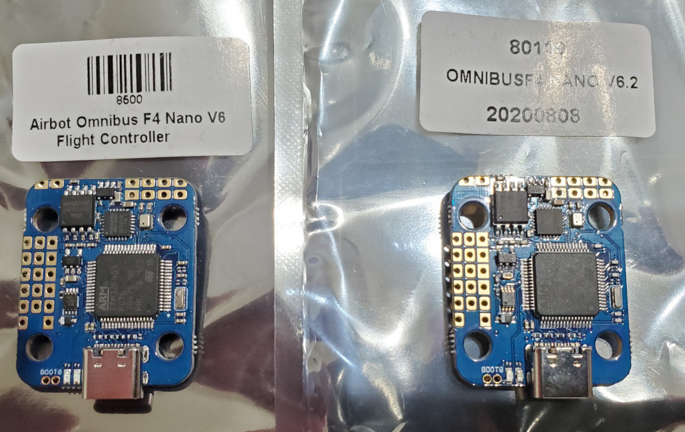
Got the boards from my colleague. They look identical. The only difference seems to be the ground-off OSD chip, but then again @brad112358 had that on his 6.1
Sorry for the potato-quality photos. If better ones would help, I can retake.
i haven’t actually tried, but i’d say if you set the GPSes output accordingly in u-center you might get away with a single signal wire. PB6 most likely won’t work, but you might want to try on RX4 (=ESC telem pin, defaults to SERIAL2 in runtime) if you don’t use BLHeli telemetry.
I received a replacement V6.1 board from GetFPV over the weekend. I have installed it on my 4 inch 190g, 33 minute flight time build. OSD and everything else is now working great. When all is said and done, the only new feature over the V6 for ardupilot seems to be current readings for ESCs which supply the analog signal but don’t track current via telemetry. It’s too bad we didn’t get an extra usable full serial port, but at least we didn’t loose one. Luckily, it turns out that the hwdef already included the current pin even though the V6 didn’t connect it.
I’ve posted details of my build here: https://discuss.ardupilot.org/t/microarducopter-3-props-omnibus-nano-success/32568/918
–Brad
Hello guys. I’m new at AP with a new board V6.1 you have as well. As far as I see currently it will be very challanging to get everything to have some autonomous moves with my drone. At the end I would like to integrate the drone into ROS with help of a raspberry Pi 3b.
I would like to thank all of you for your investigations in the topic regarding the new board I learnt already very lot. Thanks for that.
At first I would like configure the battery voltage and current monitor but I’m stucked and I would need help based on your experience. As I saw the hwdef from most recent release (4.0.3) contains already current pin (11) and voltage pin (12) definition as Brad mentioned. It would be straightforward but when I set 12 to BATT_VOLT_PIN and 11 to BATT_CURR_PIN I’ve got values that are continously changing without reason. (I have built in current sensor in 4in1 ESC.) When I measured the battery voltage with multimeter and typed into Mission Planner -> Setup -> Battery Monitor -> Measured Battery voltage then I get value of 806(!) for BATT_VOLT_MULT parameter that is unreal. And with this value the Battery monitor does not work well it does not follow the draining of the battery. So my assumption is that maybe I use a wrong pin for BATT_VOLT_PIN and BATT_CURR_PIN.
Could you please give me an advice how can I check whether I use correct pins or not for battery voltage/current monitoring?
Thank you for your help in advance.
the hwdef’s pin definitions are correct. the volt pin expects direct battery voltage connect, that’s what the multiplier defaults for. check what voltage your individual battery monitor hardware outputs, maybe check the hardware’s specs or post a link to the actual hardware you’re using so we can help.
the current pin’s amp per volt scaling of 18.2 is a point to start from and requires adjustment according to you individual hardware’s specs too.
on a sidenote, respective updates to the board’s wiki page have just been merged and will be online soon.
Thank you for your help and sorry for my late reply. My board is getting the battery voltage directly from 4in1 ESC so the VBAT on board has the battery voltage. You mentioned “volt pin expects direct battery voltage connect”. Does it mean I need to connect the battery voltage directly to PC1 pin of MCU? Does not PC1 pin get the VBAT directly? I does make sense for me.
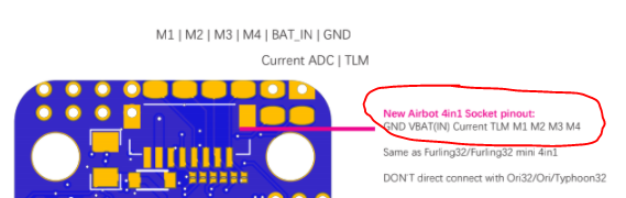
About the wiki page of the new board: I have v6.1 and the ESC connector has different pinout. It has this one (I double checked it today):