Need help with tuning rover

Hi,

I’ve just started the process of tuning my rover.
I’m currently running the latest ardurover code
from the master branch
3.2 - rc2 .

I’m running a version with pivot steering fixed in auto and steering mode.
I’m also running the code via Navio2 with a reach rtk module.

when I first started I initially set my waypoints like this . Some of the waypoints were placed very close to each other (around 0.5 metres)

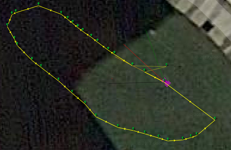
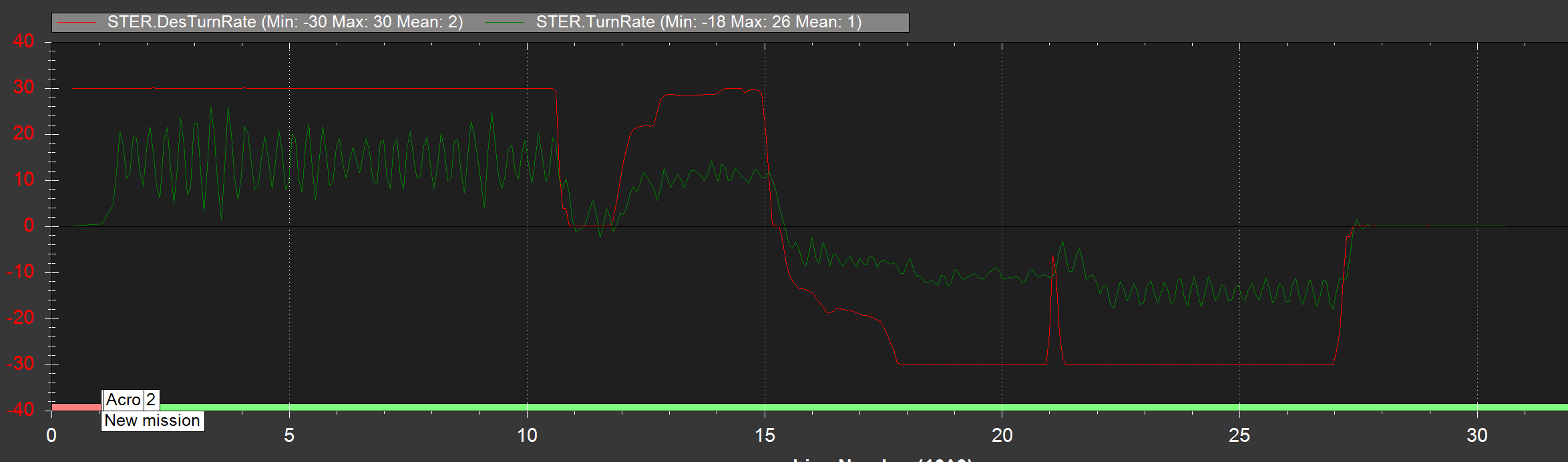
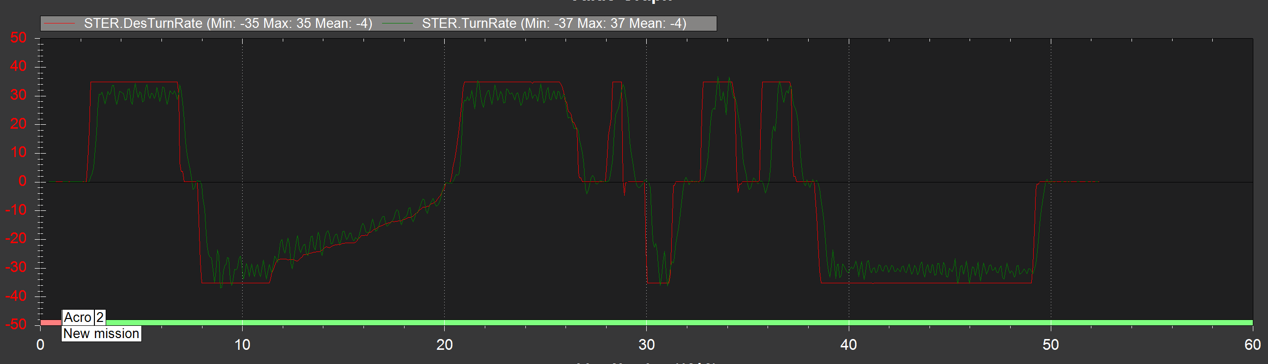
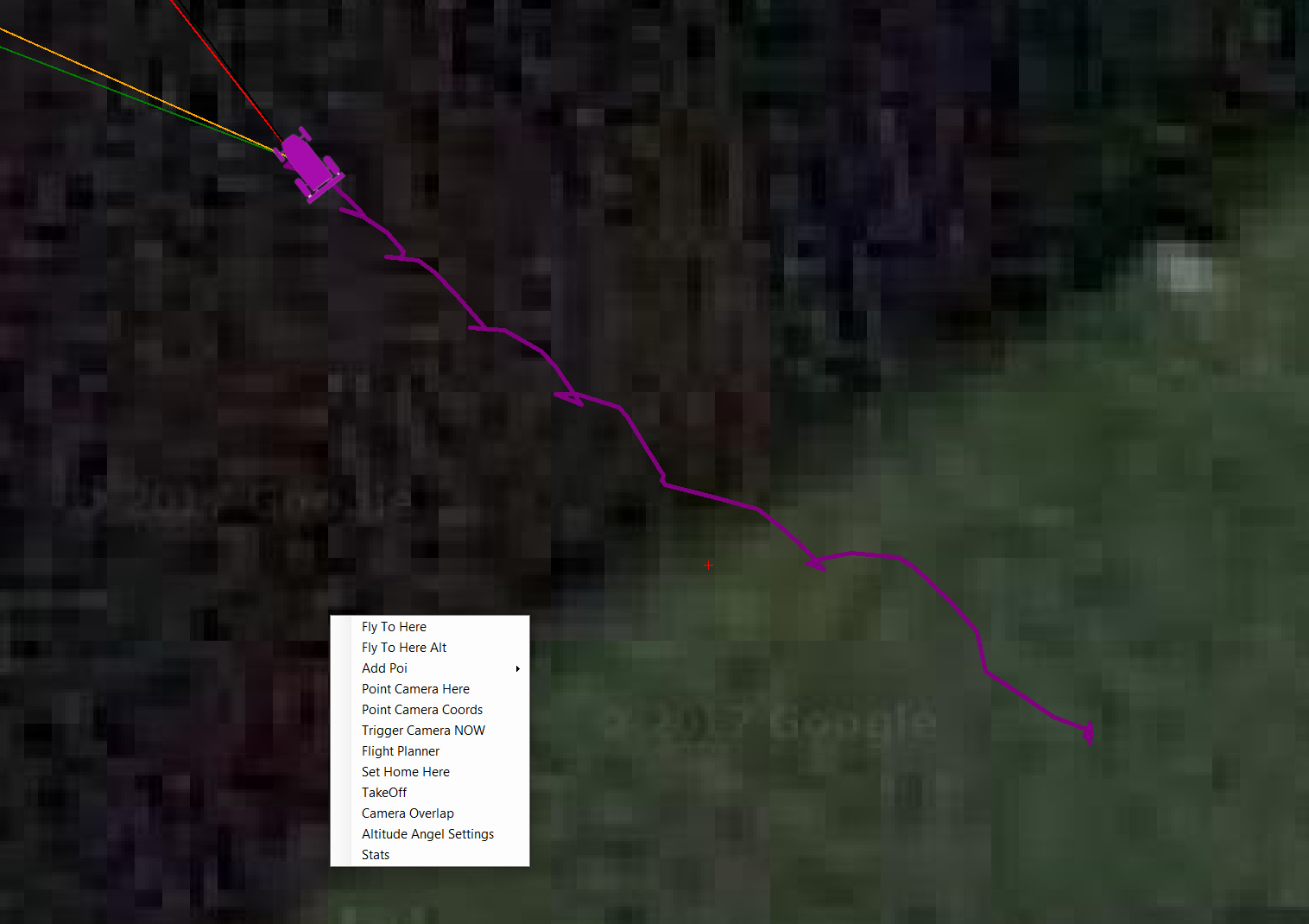
and my rover is doing something crazy like this when try to hit the way points and weaving all over the place

I also noticed that even though in my flight planner panel the waypoints look smooth. In my Flight data panel mission planner the waypoints look like this. It looks as if some of the way points were rounded off and are stacked near each other.

My skid steer platform is quite slow. maximum speed is approx 0.35 to 0.4 m/s and weighs close to 90 Kg.

Currenlty I set the cruise speed to 0.35 with cruise throttle at 100 %

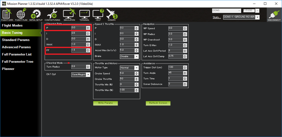
I keep seeing reference to STEER2SRV_P - is this now called TURN_RADIUS? – for a skid steer system wouldn’t this be zero?
In my config I just put a really low number 0.1.

Also what are the equivalent variables for the following
STEER2SRV_TCONST, STEER2SRV_I, STEER2SRV_D and STEER2SRV_IMAX.

the documentation seems out of date and tailored towards ackerman steering vehicles
http://ardupilot.org/rover/docs/tuning-steering-and-navigation-for-a-rover.html

Also because my robot is heavy and very slow can I turn up the
TURN_MAX_G to the maximum value (10). There is no way my robot can skid or roll. How does this value affect my the controller?

Below are a subset of my parameters
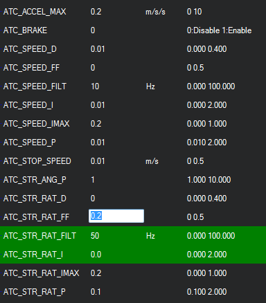
ATC_ACCEL_MAX,0
ATC_BRAKE,0
ATC_SPEED_D,0
ATC_SPEED_FF,0
ATC_SPEED_FILT,5
ATC_SPEED_I,0.2
ATC_SPEED_IMAX,1
ATC_SPEED_P,1
ATC_STOP_SPEED,0.1
ATC_STR_ANG_P,2
ATC_STR_RAT_D,1
ATC_STR_RAT_FF,0
ATC_STR_RAT_FILT,5
ATC_STR_RAT_I,2
ATC_STR_RAT_IMAX,1
ATC_STR_RAT_P,0.5

COMPASS_AUTODEC,1
COMPASS_CAL_FIT,16
COMPASS_DEC,0.2100157
COMPASS_DEV_ID,393730
COMPASS_DEV_ID2,262402
COMPASS_DEV_ID3,466441

COMPASS_EXTERN2,0
COMPASS_EXTERN3,1
COMPASS_EXTERNAL,0
COMPASS_LEARN,0

COMPASS_OFS3_X,-19.80848
COMPASS_OFS3_Y,23.99739
COMPASS_OFS3_Z,-107.0519
COMPASS_ORIENT,0
COMPASS_ORIENT2,0
COMPASS_ORIENT3,8
COMPASS_PRIMARY,2
COMPASS_TYPEMASK,0
COMPASS_USE,0
COMPASS_USE2,0
COMPASS_USE3,1
CRUISE_SPEED,0.35
CRUISE_THROTTLE,100

MAG_ENABLE,1

MOT_PWM_FREQ,1
MOT_PWM_TYPE,0
MOT_SAFE_DISARM,0
MOT_SKID_FRIC,100
MOT_SLEWRATE,100
MOT_THR_MAX,100
MOT_THR_MIN,0
NAVL1_DAMPING,0.95
NAVL1_PERIOD,2
NAVL1_XTRACK_I,0.05

PIVOT_TURN_ANGLE,45

RCMAP_PITCH,1
RCMAP_ROLL,2
RCMAP_THROTTLE,3
RCMAP_YAW,4

SKID_STEER_IN,0
SPEED_TURN_GAIN,40

TELEM_DELAY,0
TURN_MAX_G,10
TURN_RADIUS,0.1

WP_OVERSHOOT,0.5
WP_RADIUS,0.2

Any pointers would be very helpful

any progress? I’m with similar problem in my ASV…

Today I attempted to tune my rover - using ardurover version 3.2 - RC4 - using the new instructions recently posted on the wiki

  1. Speed tuning - http://ardupilot.org/rover/docs/rover-tuning-throttle-and-speed.html
  2. Turn rate tuning - http://ardupilot.org/rover/docs/rover-tuning-steering-rate.html

I never got to seriously look at Nav tuning as I got stuck with the speed and turn rate tuning
I will attempt to describe what I did and what problems I’m seeing

Firstly, this is what my rover looks like: https://www.youtube.com/watch?v=3xL8Db60YUk

It is a slow 110 Kg robot. towards the end of last year we decided to incorporate APM as the main autopilot for the system. The robot’s top speed 40 cm per sec with a max turn rate of about 30 - 40 deg per sec.

The first thing I did was to learn the cruise throttle using the Aux switch to learn the cruise speed. This worked without any problems.

Then I attempted to tune the speed. I switched the rover to ACRO mode, then drove in a straight line. What I noticed is that the piddesired and pidacheived for speed tuning hardly ever moved. it was always showing unit value of 0 on the graph like in the sample image

I tried playing around with the speed p and feed-forward values until it looked visually ok before moving onto the steering tuning as I was not seeing a sensible readout in the piddesired/pidacheived graph for speed. And yes I did change the GCS mask to 2 for throttle.

I changed the GCS PID mask to 1 to start looking into steering mode. I noticed that whenever I gave a spot turn command, ardurover tries to command a turn rate which the robot is not able to acheive (by a huge margin).

I change the ACRO_TURN_RATE parameter value to 40 deg per sec from the 180 deg per sec default and that did make things more reasonable. I tried to tune the steering as best as I can by performing a series of spot/pivot turns.

However when I switched to steering mode. I noticed that in this mode as well as in auto mode it again tries to command a turn rate which the robot cannot achieve.

So 2 questions I have is

  1. How is speed tuning properly visualised?
  2. How can we reduce the commanded turn rate so it is not trying to command a turn rate that the robot will never achieve in steering and auto mode like in the acro_turn_rate parameter?

It seemed as though tuning the steering in acro mode had no effect when the robot was in steering mode or auto.
I robot still weaves around between waypoints.

See below for logs

Log of me demonstrating a spot/pivot turn in steering mode attached.
https://cloudstor.aarnet.edu.au/plus/s/s7Cb9NRLK3P6JZ8 - download link password - ‘ardurover’

Here is another log file of me attempting to just run the rover in auto mode just to see if the parameters I tuned in acro mode made any difference in auto mode -
https://cloudstor.aarnet.edu.au/plus/s/XVhEhhnUnL4A7KC -download link password - ‘ardurover’

Esa

EDIT: I am using reach RS rtk gps for my positioning . During my tuning process I was getting a good GPS rtk fix most of the time.

Esa,

Ok, so it looks like we have a problem where the speed desired and achieved is not being sent to the ground station in Acro mode, it will only be sent in Auto, Guided, RTL and SmartRTL. I’ll fix that up for the final release (or -rc5 if we need one of those).

The next best way to look at the throttle response is to look at the THR and PIDA messages in the dataflash logs.
It’s probably best to set the ATC_SPEED_FF parameter to zero. I’ll make this clear on the speed tuning wiki page.


The speed tuning in the 1st (smaller) log file looks OK (see above). It’s a little jumpy but I’m not sure if that’s real or GPS noise… maybe the ATC_SPEED_FILT could be reduced.

The speed tuning from the 2nd (very large) log doesn’t look great because the actual speed is going up and down a lot. I’m a bit unsure if the vehicle is actually increasing and decreasing it’s speed a lot or whether we are just seeing the limits of the speed accuracy when using a GPS.

For steering tuning, there’s not much driving done in ACRO mode (just a few turns in the large log). It looks like when this log was made, the ACRO_TURN_RATE parameter was 180deg/sec but I can see in the smaller log that it’s now been reduced to a more reasonable 30deg/sec. I think ATC_STR_RAT_FF should be much higher, and ATC_STR_RAT_P should probably be reduced to zero.

TURN_MAX_G should probably also be reduced from 1.0 (G) to 0.2-ish. This will reduce the desired lateral acceleration during pivot turns… at 20cm/s the lateral acceleration is almost zero.

Is ACRO_TURN_RATE used in AUTO mode? does it limit TURN RATE in AUTO mode? It seems not in rc3.
So, TURN_MAX_G is used in PIVOT TURN? Lowering this parameter we could decrease PIVOT TURNS SPEED?

Thank!

Hi @rmackay9,

I took your tips and I think I managed to get speed tuned to a point where I am happy with for now. I also just discovered how to discretise my logs using the LOG_FILE_DSRMROT parameter. :slight_smile:

Log file for speed tune attached
https://cloudstor.aarnet.edu.au/plus/s/uPo18eAofhpXjtr

This is what it looks like

I was not able to remove the jagged signals, I’m going to assume that this is from the reported GPS speed ? @rmackay9 I’m assuming in your system you use encoders on your motor to get cleaner speed values?

I still have issues tuning the steering rate in acro mode. The output steering rate is severely restricted. I’m having problems getting the output turn rate to go past 15 deg / sec

here is my ATC starting values

I followed the instuctions according to the wiki by first setting
ATC_STR_RAT_I = 0
ATC_STR_RAT_D = 0
Acro turn rate max to 30
TURN_MAX_G = 0.2

I could not set ATC_STR_RAT_P to 0 as minimum value required is 0.1 … so I left it at that

I also bumped up the ATC_STR_RAT_FILT to 50 Hz just to see what happens . it was on 10Hz previously

I then started playing with the ATC_STR_RAT_FF values
first starting with 0.2

see log: https://cloudstor.aarnet.edu.au/plus/s/8MdoW5nKcvgqrmz

this is what it looks like

increasing the value of ATC_STR_RAT_FF to 0.5 (Maximum) gives me this. notice how the output turn rate values have increased (although not enough)

Log file: https://cloudstor.aarnet.edu.au/plus/s/0mXcbCAKFmL2PmV

I know the platform is more than capable of achieving a turn rate of 35 -40 deg per sec as seen here in manual mode where it can easily output turn rates of 35-40 deg per sec.

The only time I could bring the Output steering turn rate to approach the 30 to 40 deg per sec line was when I started to put in some ATC_STR_RAT_P values like 0.8. But the effect of that was the robot started to turn in a very jerky way. The graph was oscillating all over the place. Did not look good at all. It is as if my steer output values are stunted by something and I don’t know what it is.

It would be nice if I could try ATC_STR_RAT_FF values greater than 0.5 just to see what happens.

Not sure what else to try

Esa,

Nice work on the speed tuning. That looks much better.

The 0.5 limit on the ATC_STR_RAT_FF is a mistake in the parameter description as is the lower limit on the P value. I’ll fix those. For now, you can set the gains directly and avoid the limits by using the MP’s full-parameter-tree or full-parameter-list screens. if those aren’t available try going to the Config/tuning >> Planner page and set the layout to “advanced”.

It looks like a very high FF value is required on your vehicle. Maybe 3.0? Anyway, you’ll find out I guess :-).

Yes that is how I’ve been setting the values via the

full-parameter-tree or full-parameter-list screens with layout set to advanced

I noticed if I input a value like 0 for ATC_STR_RAT_P to zero … the next time I load up the parameter tree . the values default back to 0.1.

I’ll try it again tomorrow but I was certain that when ever I entered a value that was out of bounds the next time I loaded the parameter setting the default lowest/maximum remain. Maybe I’m seeing things …it was a long day

I’ll try again tomorrow

Thanks for your help so far

Cheers
Esa

Ok, thanks for checking.

If a parameter is being increased or decreased from what you’ve set it to then it’s most likely that it’s the ground station doing it so we could ask MichaelO to look into that.

ok …let me double check tomorrow.

If I can’t set my ATC_STR_RAT_FF beyond 0.5 or set my ATC_STR_RAT_P to zero tomorrow via MP I’ll let you know.

@rmackay9

I can confirm that I am not able to change the ATC_STR_RAT_FF beyond 0.5
and ATC_STR_RAT_P cannot be set to zero from Mission planner. I attempted to write
ATC_STR_RAT_FF = 3 and ATC_STR_RAT_P = 0 and reloaded the page and noticed that the values remain at 0.5 for FF and 0.1 for P.

I switched to QGroundControl and I can change those values successfully.

ATC_STR_RAT_FF was then set to 3 in QGroundControl
and ATC_STR_RAT_P was set to 0.

I then switched back to Mission Planner and I can see those changes when the parameter tree was loaded.

I then tried to change the ATC_STR_RAT_FF value to 2.5 in Mission planner, clicked write param and then refreshed the param tree. Again Mission planner did not allow me to write the param. It basically retain the ATC_STR_RAT_FF = 3 that I did previously with QGroundcontrol.

Currently running Mission Planner 1.3.52.3

@Michael_Oborne do you know what this could be?

Esa

I had some more success today tuning the steering rate controller. I had to use the work around that I mentioned above to modify the ATC_STR_RAT_FF in QGround Control then switching to MP to monitor the result until I got something acceptable.

Currently using 1.35 as the value with a tiny pinch of I.

I did this test indoors under a GPS repeater. I’m assuming the actual turn rate value is calculated by looking at the compass read out ?

I will test again outside when I get the chance.

Randy, Do you know what could cause the jagged signals on the steering rate? IS GPS used to calculate steering rate?

logs attached - https://cloudstor.aarnet.edu.au/plus/s/KFnx6xVmeP7MX9g
link password ardurover123

Now onto the NAV tuning

Hi All,

I did a short test yesterday where I tried to tune the NAV params.

I tried to do a simple waypoint following Path. (Square with 4 waypoints).
Again throughout the whole test I had good RTK fix solution.

I wasn’t getting a nice solution. A quick inspection of the logs show that the desired acceleration is way higher than what my rover can do.

See below

logs: https://cloudstor.aarnet.edu.au/plus/s/ME8D2CfgLJ07of4 - password ardurover123

I tried playing with the NAV1 params
lowering the Nav1 period resulted in the rover weaving at a faster frequency as it traversed from Waypoint to waypoint. Increasing the Nav1 period resulted in lowering the weaving frequency. but it also meant that the rover deviated from the path with a larger amplitude. So to summarise

lower Nav1 period = higher oscillation freq, but the rover’s position is closer to the path
higher Nav1 period = lower oscillation freq, but the position’s position deviated alot more from the path.

I played around with the Nav1 period to make it go all the way up to 50.

my current turn max g is 0.2 but I think it needs to be more like 0.02 …is this possible in ardurover ?

Also is there a way I can make the EFK trust the gps more? I am using an emlid rtk gps with ntrip corrections.

only thing i can think of is the EK2_POSNE_M_NSE param.

I was thinking of reducing this to something between 0.5 to 0.2

Hi @rmackay9,

Any chance I could get your opinion on some of my questions above?

I’m keen to do more testing but would like some direction before I go out.

Any pointers would be greatly appreciated

Hi Esa,

Sorry, I missed your message. I’ve been checking the Rover-3.2 forum but forgot about this one.

I’ve just tested the latest beta Mission Planner and it looks like MichaelOborne has updated it to include the FF with new ranges. I should add though, that even before updating to the latest beta, I’ve successfully set the ATC_STR_RAT_FF to large numbers using the MP’s full parameter tree page which doesn’t do any range checking.

Re the jagged turn-rate. The actual turning rate (i…e STER.TurnRate) comes from the EKF which uses a combination of gyros and the compass (No GPS required). It might help to set ATC_STR_RAT_D to zero although I don’t think the controllers are the cause of the jagged response. I suspect it’s in the frame somehow.

It looks like the 2nd log (16.BIN) is from an Octa-quad but 100.BIN is from a rover so I’ve had a quick look at that log… no navigation in this earlier log though so I can’t comment much about the large desired lateral acceleration you’re seeing. If you’ve got another log I can have a peek.

Some comments about this questions?

Is ACRO_TURN_RATE used in AUTO mode? does it limit TURN RATE in AUTO mode? It seems not in rc3.
So, TURN_MAX_G is used in PIVOT TURN? Lowering this parameter we could decrease PIVOT TURNS SPEED?

Thank!

HI @rmackay9,

Are you sure you were looking at the right log ?

The second log is 00000106.BIN not 16.BIN as you stated.

It is 9444 KB in size

Esa

Leonardo,

ACRO_TURN_RATE is not used in Auto mode, only in ACRO mode. I have a patch that adds a parameter to set the vehicle’s maximum turn rate but it needs more testing so I did not include it in Rover-3.2.

Yes, TURN_MAX_G is used during pivot turns in Steering, Auto, RTL, SmartRTL and Guided modes. Reducing this should reduce the aggressiveness of pivot turns.

For 3.3 I hope to improve the way pivot turns work. The current method is quite rough really.