Can’t the gps module & power module I already have be used for the pixhawk?
I did not know you had a power module. My bad. I get some of these post mixed up sometimes. If your GPS has a compass in it also you should be good. I thought it was only getting 7 or so satellites but I don’t know the environment it was being used in. Take it one step at a time and all will be O.K…
All the peripheral devices you have will work but you will have to put new connectors on the GPS and telemetry radio cables or find new cables for PIxhawk. No idea about your analog input device.
@iampete @David_Boulanger @dkemxr @ktrussell hey guys I hope your all keeping well. Had allot going on so haven’t much time with the Pixhawk 2.4.8.
Managed to change the wiring on the GPS module as @dkemxr mentioned and all works well. Just a list of what I’ve done so far:
•Installed firmware via mission planner
•Calibrated the pixhawk & gps module using wizard
• receiver inputted into RC port on Pixhawk
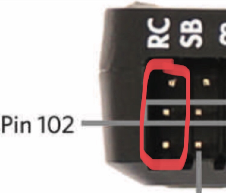
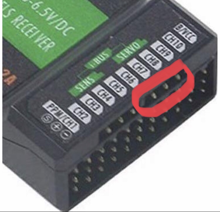
•receiver output seems to only work in Radio Calibration when plugged into the following port.
With the old apm it was channel 1 and 3 for throttle and steering but it only seems to detect in the following port. Also the switch I’m using for auto/manual is being detected by the pixhawk:
Once I wired it up to my rover there was no movement in manual mode & on mission planner when using the switch in flight mode it wasn’t shifting up or down which it did before with the apm. Not sure what I’ve missed here. Once I’m home from work this evening the struggle begins.
The only output from your receiver that your concerned about is the PPM. And you are correct to have it go in to the Pixhawks RC terminal. Why do you have some pins on your receiver circled? I’m a little confused about your receiver. Is what you circled the PPM out or is the PPM out on channel 1. Regarding no movement. Is the pixhawk armed and are you using the safety switch? Last question is how are you powering the servo rail on the pixhawk for your steering servo?
One cable from Rx PPM/CH1 out to Pixhawk RC in is all you need. You might have to enable PPM mode on the Transmitter but I’m not familiar with Flysky.
Yes I think that’s the case and I think it’s currently on PWM and I need to change that once I’m home. @David_Boulanger the pins I have circled are the only ones that have worked and show up when I move them on mission planner. At the top of those pins it says i-bus.
Also I didn’t know I need another power source to power anything else like the servo rail, also I’m not sure if it’s armed & didn’t add the safety switch. Total noobish behaviour but will add those this evening. Regarding powering the servo rail what do I need to do?
Save yourself some initial trouble and disable the safety switch by setting the BRD_SAFETYENABLE parameter to 0. You can plug one in later if you like but I don’t use them on any vehicle or craft.
Just seen that on YouTube and instantly saved it to my favourites to do later. thank you for the heads up on that one👍🏼
Regarding the power for the pixhawk power rail, I didn’t know I need an additional power source to add to it, when I add the receiver into RC port it lights up and works.
the rc port is isolated from the servo outputs. To power your steering servo you will have to also plug in a bec, in many cases there is one built into your speed controller.
By connecting your ESC to the Pix main out CH3 (where it should go for throttle) the BEC in your ESC should supply the servo rail for the Steering servo. It’s the same setup I had on my old rover.
@dkemxr yes my motor also has BEC so once I connect it to Main out CH3 all should be ok.
I will also change the receiver mode to PPM.
I will also use the power module to the pix and have the other lipo supply power to the ESC.
Let’s hope the pixhawk saves the day this time round🙏🏼 All I want is to have it do little auto missions lol hardly rocket science but it’s been a struggle thus far. Tonight if I can get things working I will do some test runs and provide the logs for review
I don’t understand why you are using 2 batteries. One battery connected to the power module with the battery power output to your ESC and the Vcc output (6 pin connector) to the Pixhawk power connector.
If you have 2 batteries for longer run time forget that for now and get this Rover on the road with the basics.
1 Like
If radio calibration works with the i-bus connector, everything is fine. Do not use PPM. I-bus and Sbus are digital serial signals transmitting up to 16 channels, while PPM is an analog signal transmitting usually 8 maximal 12 channels.
One lipo connected to the power module going into the pix and the other connected to the ESC.
That somewhat negates the purpose of the powermodule. It provides current and voltage readings for the pixhawk/user, so you can set a low battery failsafe and see on a GCS how much juice is left. If you connect the main load to another lipo, you will never know when it is empty.
1 Like
On power module there an XT60 connector and my rock crawler RC has a Tamiya cable so I can’t attach it onto the other end of the power module. Unless I solder an XT60 connecter to it
You should solder a XT60 connector to the ESC. They are sturdier than the Tamiya plugs.
1 Like
Depending what code you are using, I would think 3.4.2, this should probably be moved to rover 3.4/3.3. I know its getting a little ahead of things.