What are you trying to achieve here? It almost sounds like your trying to set up a power module which normally would plug into the power port on the Pixhawk.
click on this and scroll down to the pin tables.
http://ardupilot.org/rover/docs/common-pixhawk-overview.html
I’m trying to achieve the use of 2 power inputs & having 2 separate readings for voltage & current from each power source.
Similar to the link I’ve provided above.
I may have figured it out now in my mind but will try once I’m home, completely different outcome usually in mind & then in reality. ile probably fry something tonight😂
Battery monitor 1 will be from the power module on the power input connector which are assigned as follows:
BATT_VOLT_PIN (2)
BATT_CURR_PIN (3)
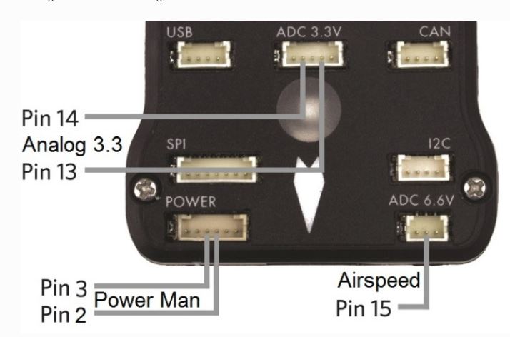
if you want to use a second battery monitor you can use “ADC 3.3V” connector and assign it as follows and connect as per attached.
BATT2_VOLT_PIN (13)
BATT2_CURR_PIN (14)
These inputs are all 3.3VC max so if your voltage to be monitored is higher than that a voltage divider is required. That’s what the power module does. For current you need a current shunt or other current to voltage device to produce 3.3V max with current. The power module also does this. You will have to scale the inputs with the BATT2 parameters.
2 Likes
Thank you very much for explaining. I think I tried this method last night but unsuccessful.
Maybe due to not having the current shunt or a second power module hooked up. I will give it a try and let you know how it goes. Thanks again for your help
On ADC 3.3v Pin 14 is for Red (Positive) and Pin 15 is for black (Negative or Ground) is that right?
I will also use the power module to connect to ADC 3.3v. How would I connect the power module to it?
ADC 3.3v has 5 pins and Power module has 6
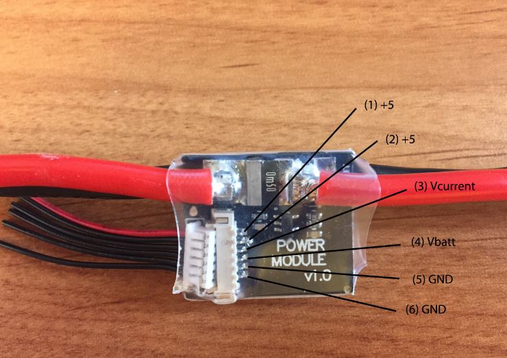
The link that David posted has the pinouts. Between that and what I posted you have all you need. Power module pinout shown in attached.
BTW-I tried the pin13 input assigned as voltage and it worked fine with a 1.5V battery input on the bench with a spare Pixhawk I have. Multiplier set to 1 in that case as no divider was needed.
What voltage and current levels are you trying to monitor? I still don’t underatnd what you are trying to do. What are these sources coming from?
OK, so it’s a voltage output, current out, both? What full scale ranges?
You think?
No, +5 is power output from the module to power the Pixhawk. Vbatt is voltage divider output and Vcurrent is current equivalent voltage output. I’m going to guess that this current will be very low and the power module will not be suited as a shunt for this. It’s intended for high levels of battery current.
1 Like
I’m just guessing you guys are on another level compared to me so even if I look at the pinout parameters it looks alien to me. I really don’t know what I’m doing without you guys.
Yes it will be very low so from what you’ve explained the power module won’t be suitable either for what I want. I guess ile have to find something with allot more power to make it suitable.
Is there no other way of measuring small amounts of voltage & current?
What about this, could this work?
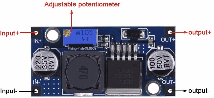
Boost Converter Module XL6009 DC to DC 3.0-30 V to 5-35 V Output Voltage Adjustable Step-up Circuit Board
Sure there is but you have to know what voltage and current levels you are working with before you can spec anything. I don’t know anything about metal detectors, does the device have a analog output or are you taking the output from the PCB that drives a buzzer or LED? If you know nothing about this signal, which is apparent, then you will want to scope the output under no metal and metal activated conditions and see what is produced.
I will have to test it. I have a device that measures voltage and current so I will look into that once I’m home and take it from there. Maybe that module I just posted might be a solution to boost the power to make it worthy for use with the power module.
Regarding the power module and the wires that I need to connect it to the ADC 3.3v could you please let me know which ones to connect?
I know you said the info is there on the parameter list that got posted but if I’m being honest I don’t understand how I will do it
For crying out loud Mus that would be ridiculous to use a Boost converter on a signal only so it could be dropped again through a voltage divider. If the voltage is less than 3.3V you can input if directly. If it’s higher than that you can use a simple voltage divider.
Forget about the Power module for this purpose, it is not suited to what you are trying to do.
I thought you said the voltage and current would be too low to be used on the power module so that’s why I thought of doing that. It’s my noobish brain creating random ideas I’m sorry.
I will do as you said with measuring what the device produces first and then decide wether to hook it directly to the ADC pins or go through the power modules. Apologies I’m babbling away on my end🤦🏻♂️
Ok so I will forget about the power module.
I will connect the red wire from the device to pin 13 and the black wire to Pin 14 and make the settings in MP for:
Once I do this if it works I will be able to see on battery monitor 2 window
No! Assuming it’s a voltage level that doesn’t exceed 3.3V and it’s DC then connect the red wire to the ADC pin shown in my illustration as Pin 13 and the black wire to a ground pin. This asumes of course that Red is +V and black in Gnd.

1 Like
Thanks for showing me I will measure the device readings tonight and see if the voltage exceeds 3.3v
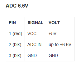
If it does could I plug it into ADC 6.6v instead?
Yes, you could do that. It has a 2:1 divider built in. If you do that set this parameter instead and use the pinout from the 6.6V connector table.
BATT2_VOLT_PIN (15)
Based on several DIY detector circuits I checked out, including one in a paper written about a mine detecting Rover, the signal will be AC which typically would drive a speaker. If this is the case with your sensor then you would want to rectify the signal. But you will need a oscilliscope to determine this. A typical multi meter will not tell you much.
1 Like
So I would only be connecting one wire (red-positive) to pin 15 and leaving the black wire out?
Or connecting the black wire on the last pin on the right hand side of ADC 6.6v & would that be classed as Pin 16?