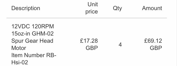
Ordered the motors:
Let’s see how good these are👍🏼
I think they are the same motors you have with a different gear ratio.
Did I choose the right ones that you suggested?
Yes, the 120rpm version of the motors that vehicle comes with. Should be drop-in replacements.
Hello All,
It’s been a long while & hope you are all keeping well. The last post was regarding a motor upgrade 50:1 gear ratio which I waited a long while for delivery but they have finally arrived. I have been busy putting all the existing hardware into a new chassis. The first was on the rock crawler which didn’t have skid steer:
The second try was on the Lynxmotion A4WD1:
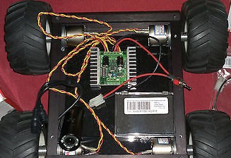
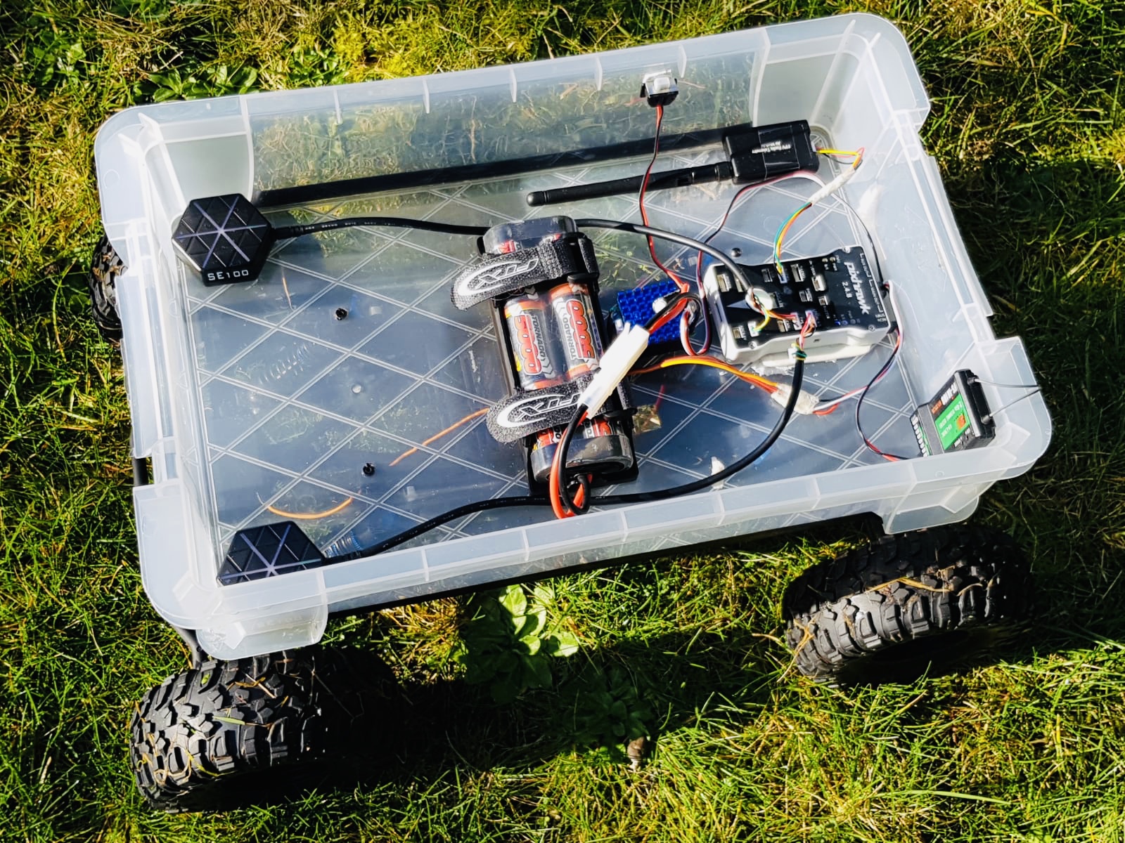
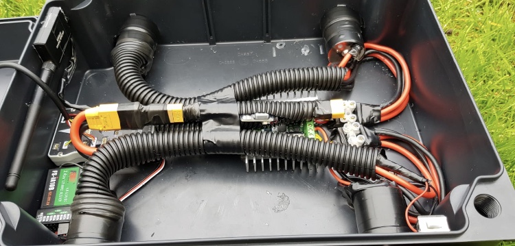
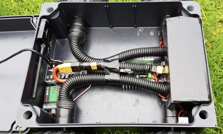
Here are the latest pictures of what I’ve completed so far today:
@David_Boulanger @dkemxr @ktrussell @iampete @count74 @rmackay9
So that’s yet another chassis? I assumed you were just switching out the motors on the other one.
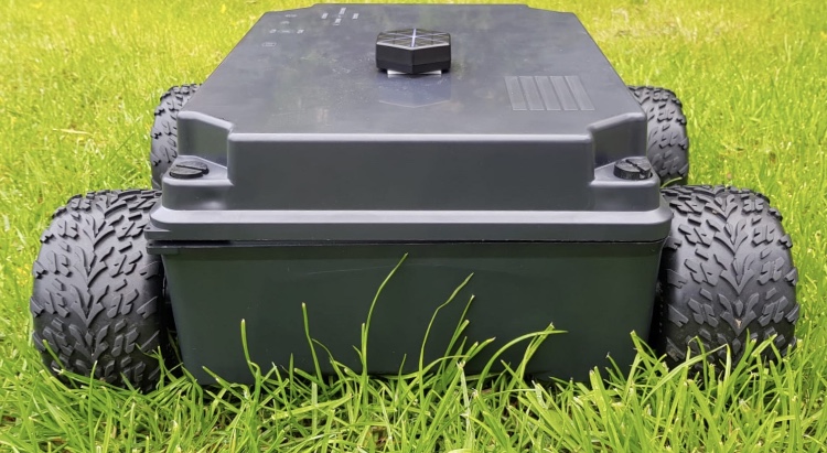
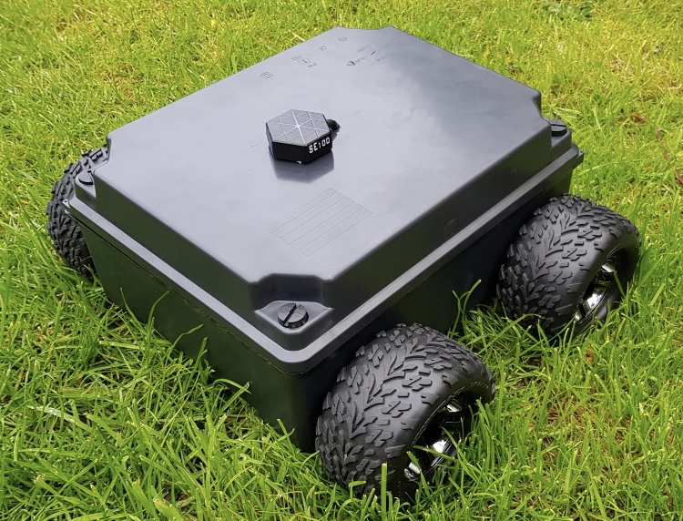
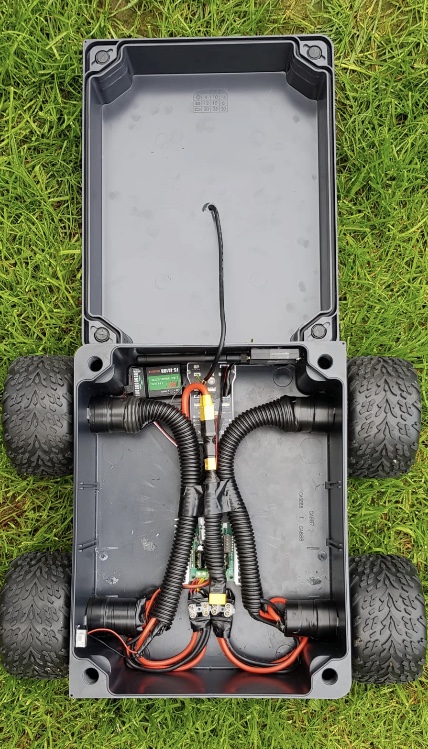
I was going to keep the A4WD1 chassis but I wanted something bigger & waterproof which the Lynxmotion wasn’t so I purchased a box for £10 and made it the new chassis. I drilled all the holes required for all the motors and installed them in today
OK. Project box skid steer Rover! Just one GPS?
I will be adding two gps modules like before but didn’t add the additional gps just yet. The gps is much better with 2 gps module after using a single module. Its far from RTK standard of course but I will be looking to get the Here+ RTK GNSS with the Pixhawk/Cube in the coming months.
Also the new motors you suggested work really well. Thank you for your advice👍🏼
Very nice, Mus! Thanks for sharing.
Hi All,
Wanted to ask a quick question regarding where I can hook up a device which I successfully managed to do with the old APM.
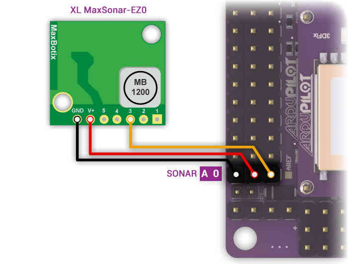
The place I wired it on the APM is as follows on the A0 Pin:
Now I need to figure out where to add this device on the pixhawk to get the same readings as before which recorded Current (CURR)
There are 2 wires from my device which are Red & Black. Not sure wether these are connected to ADC 3.3v, ADC 6.6v or the i2C Port or somewhere else.
Whichever port you all feel is suitable to mirror the same port as the A0 port on the old APM how would I connect the Red & Black wire from the device to the correct port & pins.
Thanks very much in advance
The same page the APM illustration came from for Pixhawk.
http://ardupilot.org/copter/docs/common-rangefinder-maxbotix-analog.html
I never had much luck with them on a helicopter fly over grass but for a rover maybe they are better suited.
I tried one on a quad just experimenting and it wasn’t worth the effort. Those cheap ultrasonic sensors are worthless IMO. When Ardupilot has a better handle on obstacle avoidance, not just STOP, I’ll check into Lidar.
Lidar looks awesome. Might get one eventually.
Regarding where I hook the red and black wire. That means Red is positive and black is ground? I thought black was negative? Or is it considered the same thing?
Also by wiring it into the ADC 3.3v will I be able to obtain the current reading from it like I did with the apm? If so do I need to change any settings via MP to obtain current readings from the ADC 3.3v Port or is this something that’s logged automatically?
Ground, negative, same in this case. Not all case’s though.
I don’t understand your question about current relative to the sonar sensor. It doesn’t measure that.
On the apm I wasn’t using a sonar but the device I had connected to the A0 port was giving me current readings which is what I needed. So I assumed I could use it the same way in this case with the ADC port to obtain the same current readings
No. Current is measured on the power input port from a power module.
To be clear, what current are you talking about?
In order to use the ADC 3.3v it says that the Volt Pins in Battery monitor settings can be change accordingly as the example picture shows:
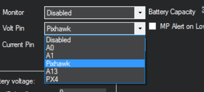
I have the latest version of MP but I don’t have the options in the Volt Pin to select a pin individually like A13 for voltage & A14 for current. If this is not possible on the latest MP firmware which version would I need to downgrade to in order to get these parameter options? It seems this has been done already by @Russj
@dkemxr @David_Boulanger @count74 @iampete @iampete @rmackay9 @mike