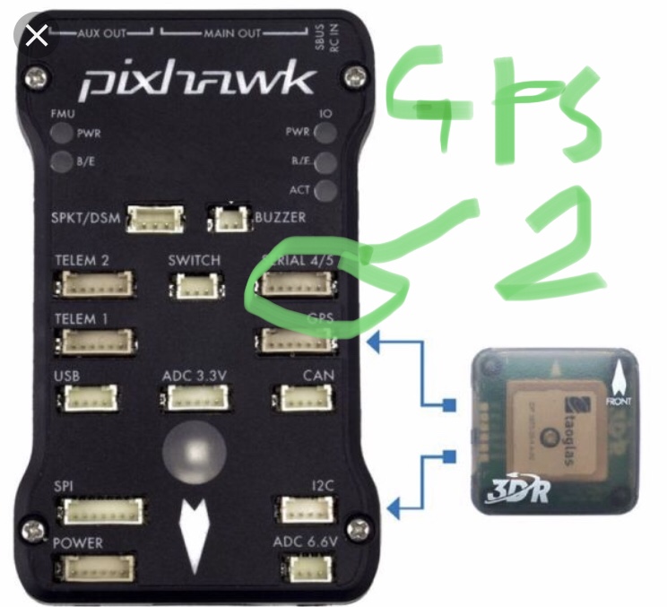
My first external is in GPS port and 12C as shown in the image above. The second external gps is in the Serial 4/5 port. Where do I add the 12C for the second compass?
I thought there was only one 12C port on the pix
My first external is in GPS port and 12C as shown in the image above. The second external gps is in the Serial 4/5 port. Where do I add the 12C for the second compass?
I thought there was only one 12C port on the pix
unlike serial i2c can do multiple devices on a single bus. So you can just wire them together. however if your to gps’s have exactly the same compass the i2c bus wont be able to tell the difference between them. So you would need to use another bus, that as you say you dont have. Some times there are solder pads or jumpers on the compass allowing you to change its address so you can use two the same on one i2c bus.
Really don’t know how to do all that, if you could provide me with a simple step by step guide on how to do this it’ll help allot.
Also is it possible that both gps are working right now or would that not be the case seeing as my second one isn’t using the i2C
gps bit of the gps uses the uart, only the compass uses the i2c. So the gps will work fine. It looks like your gps’s are the same so i would guess you cant use both compasses, see if you can find some instructions for your gps’s and it might tell you how to change the i2c address but i would guess its not possible. Your pixhawk probably came with a i2c splitter board, its just like a extension lead it connects all the i2c things in parallel.
Yes I think I have the i2C splitter board somewhere. But then I’m still left baffled with changing the address. I looked on google but can’t find anything related to my gps module and changing the address. If I open it up I’m worried I may break it.
if its not obvious or documented then its not possible
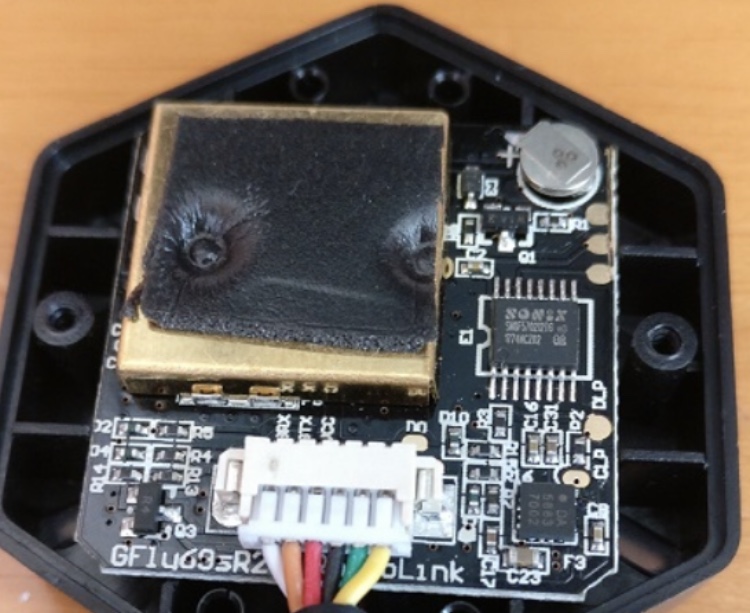
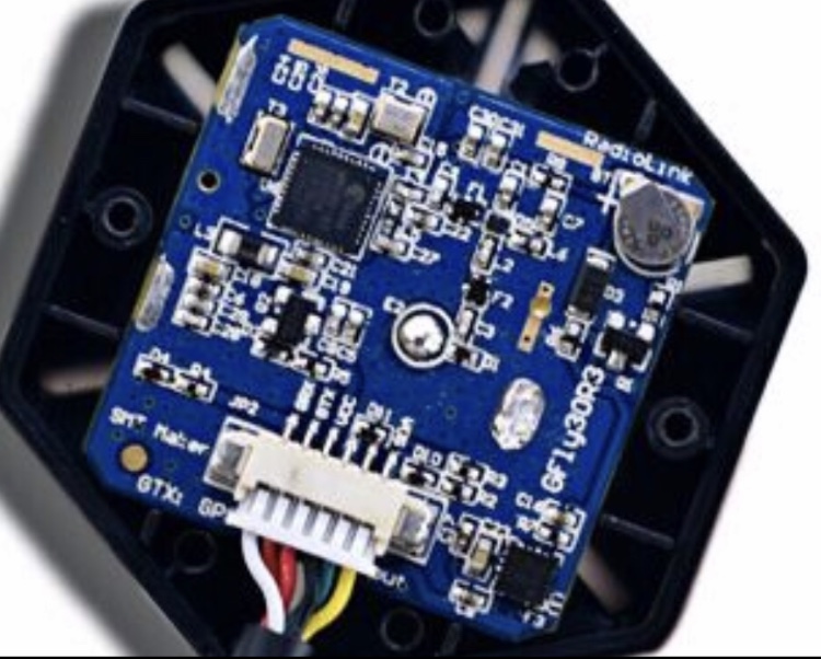
Managed to find what the inside looks like. Is there anything there which resembles what is required to change the address?
I found this about PX4:
Up to 4 internal or external magnetometers can be connected, though only one will actually be used as a heading source. The system automatically chooses the best available compass based on their internal priority (external magnetometers have a higher priority). If the primary compass fails in-flight, it will failover to the next one. If it fails before flight, arming will be denied.
So up to 4 external gps/compass can be used?
So I’m guessing 1 in GPS Port, 1 in Serial 4/5 port, 1 in Telem 1 port & 1 in Telem 2 port making 4 in total. But they say it’s best to use the same GPS module in the GPS Blending Tutorial. So if that’s the case and the pix can’t recognise them as separate it’s misleading. Like myself not all GPS have jumpers to change things around like addresses
no, I can’t spot anything, like i say if its not clear then its not possible.
PX4 is not Ardupilot
I didn’t know that. Ok so we can confirm that what I want isn’t possible but at the very least I’m happy that the gps is working on both modules & to be honest it was slightly more accurate than before & the direction of the rover was dead on in MP. So it’s made a slight difference.
Now my next step is to try the save waypoint feature and drive to 4 corners of my garden saving the waypoint on each corner. Then upload to MP to understand the offset on the MP maps as they aren’t very accurate like you guys have mentioned
You are also confusing compasses/magnetometers with GNSS/GPS modules. GNSS modules are connected to the serial ports (most of them) and compasses are connected to the I2C bus. Both are sometimes combined in one package, but they are also available as seperate sensors.
Set another channel and switch for Save WP, that’s all there is to it.
You won’t be able to use both external compass’s from those GPS modules. There are GPS/compass modules with 2 compass’s where this is possible but its because they are on 2 I2C address’s. This doesn’t much matter anyway as enabling a bunch of compass’s will typically just provide errors.
On the topic of the Google Earth being off from true latitude/longitude, what I have done is to set up my RTK base at a location I can identify on Google Earth (the corner of a small building). I then note the lat/long that Google Earth “thinks” that is and I hard code that into the base GPS as its coordinates. Then my rover appears to be at the right place on the maps, at least to the level of accuracy I need to worry about. I know that the maps could change over time and/or some other factor could affect this, but for the 6 months I have used my rover, it has been pretty much spot on.
I think for the time being I will work with what I have before eventually purchasing an RTK.
Another issue I’m having is turning radius. I would like to mod my rover to turn at least to a 45 degree angle. Right now it can’t due to the inside of the wheel turning to the point where it touches the bar. I got my rover from a company who have sent an email to someone who might know what to do. If you have any ideas seeing as your also very knowledged in the RC area I’d appreciate your throughts.
The email sent on my behalf:
That’s a great way of making sure that the base is dead on with positioning. Unfortunately I haven’t got a RTK setup or a base station “which I really want to purchase eventually”
Which RTK system have you got?
The Here+ V2 RTK GNSS is around £550 so in the future I will purchase one unless you have a cheaper alternative which also does the job, which it sounds like it does with your setup
I also did the waypoint save last night in my garden. Sometimes the point are dead on and sometimes they are off. Is there a specific amount of time the switch has to be flicked or just a really fast switch would do the job?
Once I did it the rover went round the waypoint reasonably accurate and stopped. Then tried it a second time around and it stopped exactly at the same point😁
That is awesome that you have it working well in auto. I have been using mine for 6 months and I would still say that mine is only “reasonably” accurate too as far as tracking. But, it is good enough for now.
I used a Ublox C94-M8P but it takes substantial modifications to make the base and rover communication work while letting the rover talk to the PixHawk. A single UART on the rover GPS is shared for the comm from the base and the comm to the PixHawk. One is transmitting, the other receiving, so they can use the one UART, but the baud rate has to be the same and that was a problem. I have written about it elsewhere but the bottom line is I would NOT do that again since newer ones are available that don’t have that single UART problem. The new ublox ZED-F9P is much better and has 2 UARTS. Right now, using it, as far as I know is very much a DIY kind of thing. There is not a plug and play unit. Sparkfun sells a ZED-F9P board that I plan to use for my next project. But, for the price, I think the Here unit is probably the way to go. You will have much better support from others using it. I might be the only person using it the way I am with the direct LoRa communication of the RTCM traffic.
Unless you are into programming and soldering, etc, stick to the Here unit.
Unfortunately I don’t think there is much you can do with that chassis to significantly increase the turn radius. What is it (what is your TURN_RADIUS parameter set to)? Even with the modified parts available for my truck the turn radius is 1.16m. For crawlers about the only way is 4 wheel steer which of course would be a different vehicle. Other options are a skid steer vehicle with either 2 or 4 independent drive wheels (or tracks). A zero turn vehicle like Kenny’s mower is an example.
Regarding the Save Waypoint accuracy you are still limited by the HDOP of the GPS system so there will be some positional error even if the vehicle is sitting still. You can see this in the ground station with some dithering around. Hopefully it’s manageable with what you have.
I guess I will have to look into a skid steer chassis eventually. Then I’m going to face a whole new set of problems to solve but it’s all part of the fun.
With the gps it looks like I will also eventually need to buy the Here+ RTK GPS for the accuracy that I’m looking for. This is turning out to be more expensive than I bargained for.
Is there any additional settings I can change to potentially improve the accuracy for the gps? I know there are loads of settings in the full parameter tree when you type in gps, maybe they could be tweaked for better results?
If I do purchase this will it really make a huge difference tho? I don’t want to buy it and still face accuracy issues so I want it to be worth spending £550 on, which to me is allot of money.
It will make a huge difference. As @dkemxr said, just leave your rover in one spot with the Track Length set really high in Mission Planner and watch how much it moves around over a 30 minute period.
With an RTK Fixed status, it sits very close to rock steady.
My kit which included 2 GPS units was $500.00 total. But it will not work out of the box. I had to cut some traces on the Rover GPS and use a different radio between them. If you are going to use the MAVLink injection method from Mission Planner, you wouldn’t have to do quite as much. If you decide to go this way, I will point you to some of my documentation. I need to flesh it out a little more.
If you can afford one of the ready-to-go units, your life will be easier.
Right now in MP even when the rover is fixed it moves around quite allot and then sometimes it’s pretty stable.
I think it would be best for me to buy a plug and play type like the Here+ and make this a painless procedure. Even then with the Here+ I’m sure it’ll require some tweaking.
Regarding the GPS parameters in mission planner. There are many different things shown in the full parameter tree, is there any additional things that can be changed to push the gps to a higher standard, higher frequencies etc? Maybe there are ways to push it past it’s “default” limit just like you can do with over clocking a graphics card