Mini Talon QuadPlane Conversion

Hi,

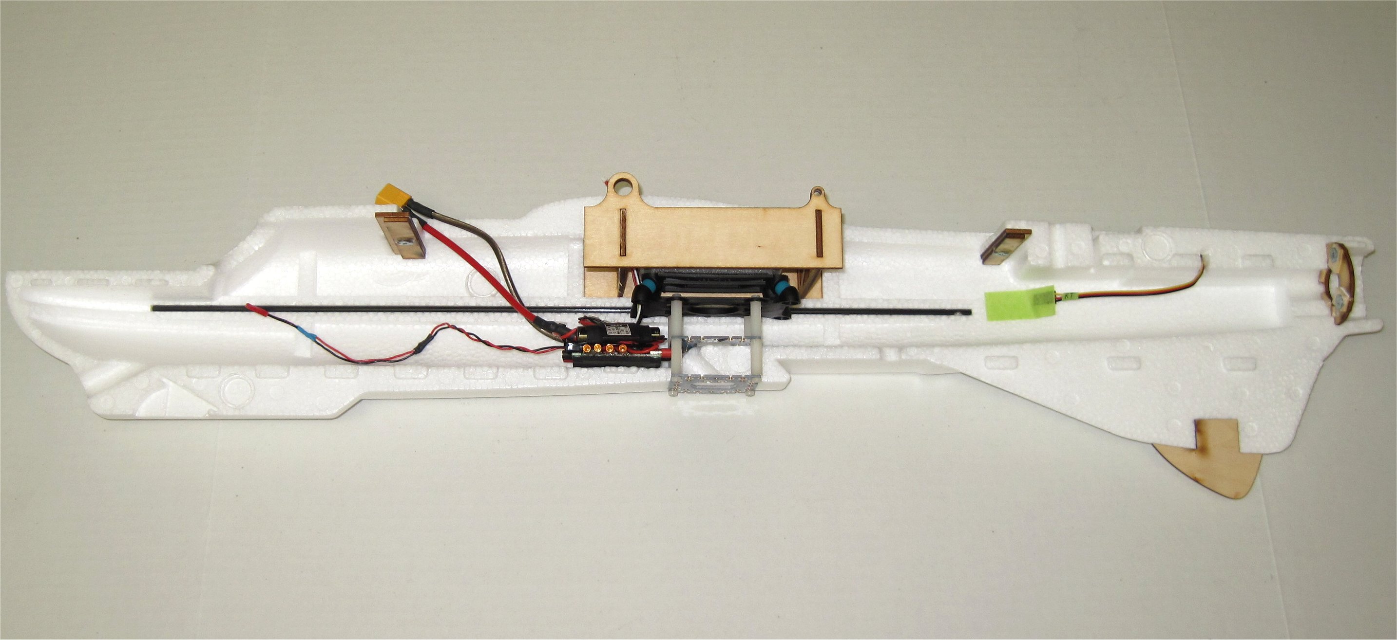
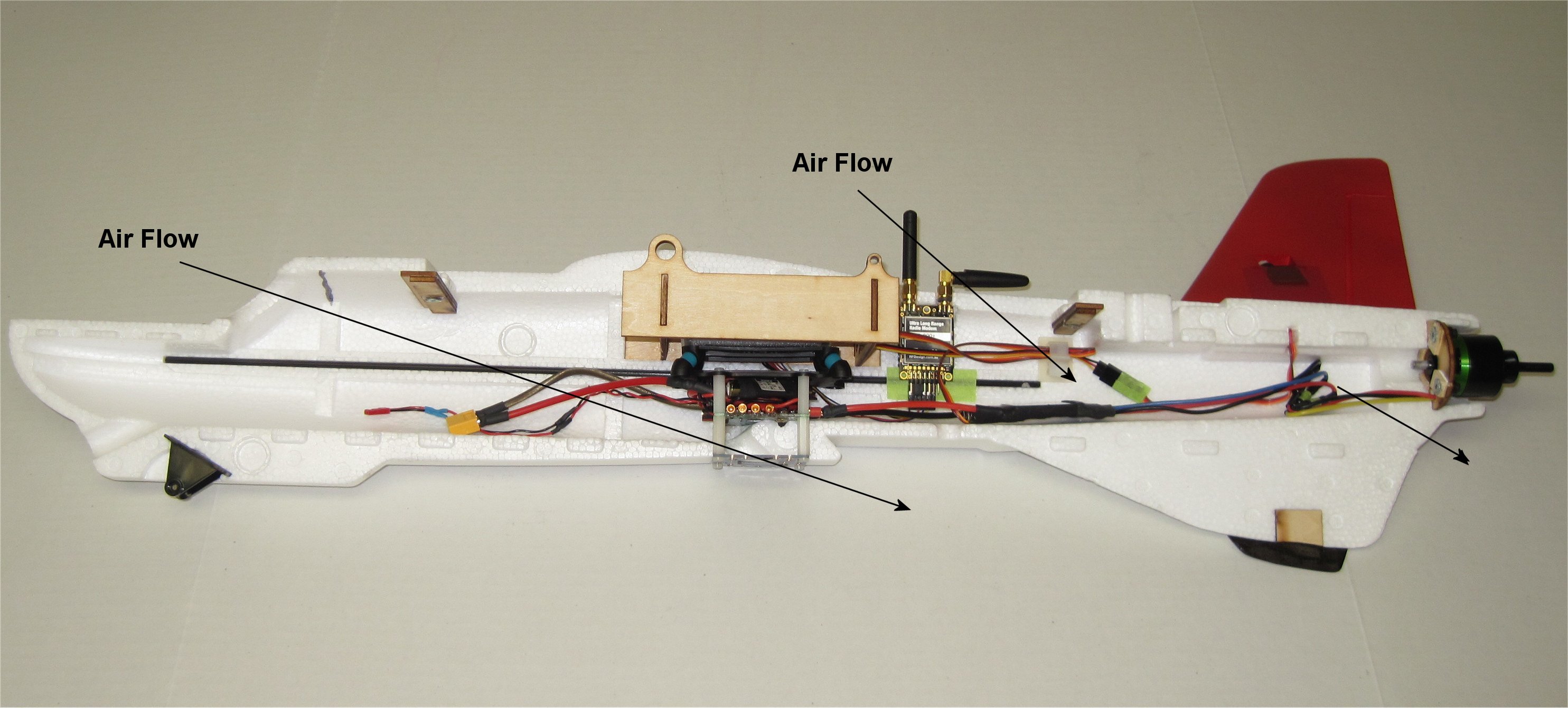
I was inspired by Sam (JeffBloggs) and the Perth UAV Club’s conversion of the mini Talon (called a Mozzie) to duplicate their creation of a dedicated QuadPlane. My conversion will be Mozzie-like and copy some of their efforts while differing mostly in the hover power system and use of the stock timber (laser cut wood).

Feel free to add your own build differences here or post questions. This is an open build thread for anyone interested in converting the XUAV mini Talon into a QuadPlane.

Here is a list of my component selections. Many of the choices are from U.S. based warehouses for easier shipping to me. Note that my plan is to use HQ 10x5 props all around. These are inexpensive carbon composite props on par with the older expensive Grauper 10x5 e-prop.

Plane Parts
X-UAV mini Talon Kit - Banggood USA - $55 shipped
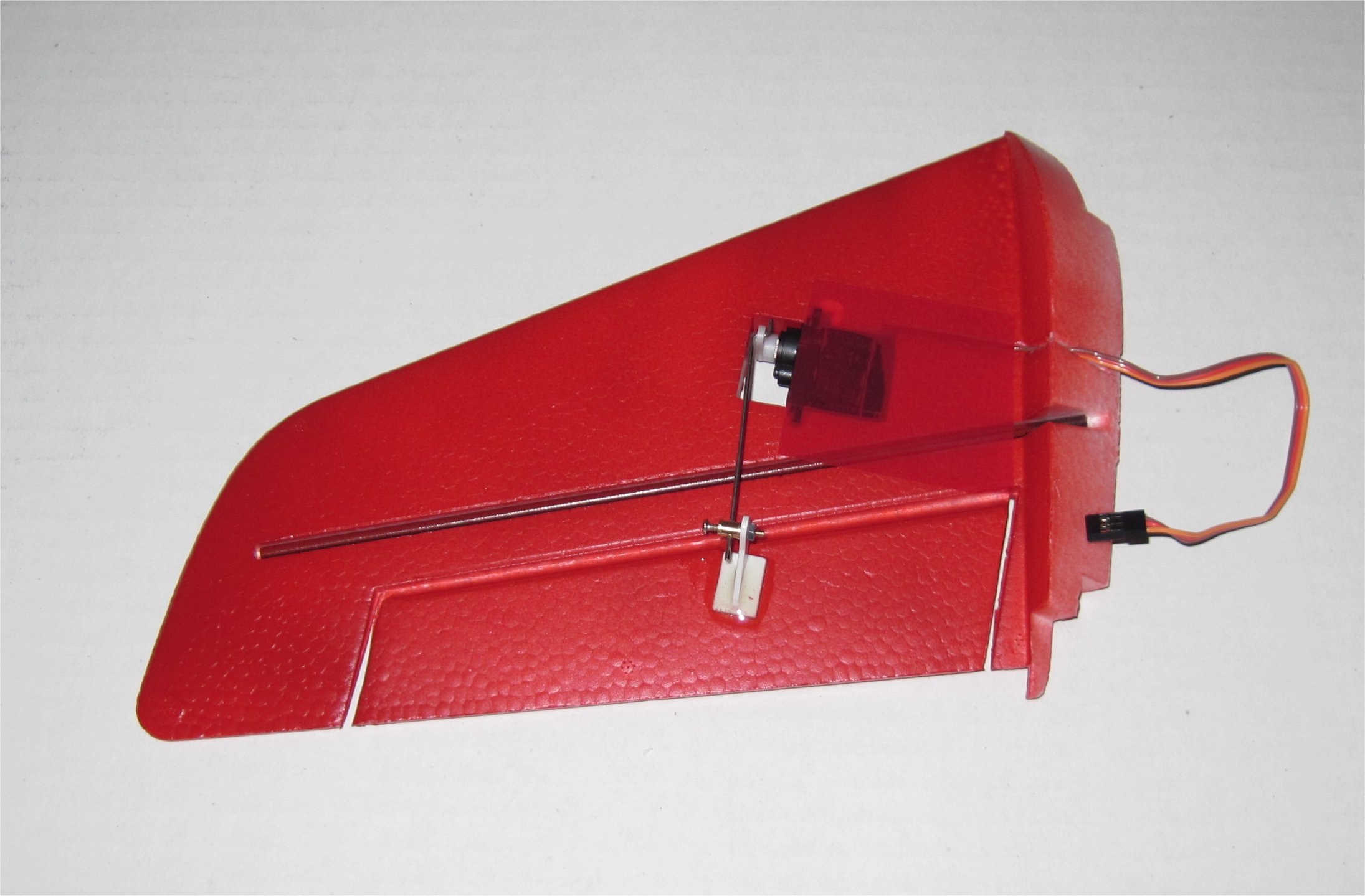
Corona Digital Servo DS-929MG 2.2kg / 0.11sec / 12.5g - HK USA - $5.88 x 4
Cobra C-2814/16 1050Kv Brushless Motor - RC Dude - $38.
ZTW Beatles 40A Brushless ESC - BuddyRC - $15.
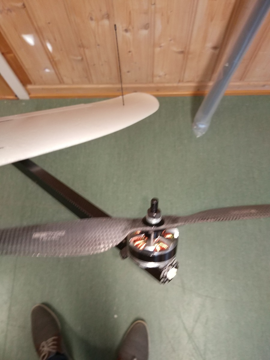
HQ Prop 10x5 E Carbon Composite Props - RTFQ - $7/pr.
Aeronaut 10x8 Black Electric Prop - Atlanta Hobby - $9.
NACA Style Inlet Duct Set - HK - $3.
3-Blade Propeller 9x4.5 Black (CW/CCW) - HK - (CW/CCW) (2pcs) for $1.90
Multistar High Capacity 8000mAh 4S 10C Multi-Rotor Lipo Pack XT90 - HK $44.
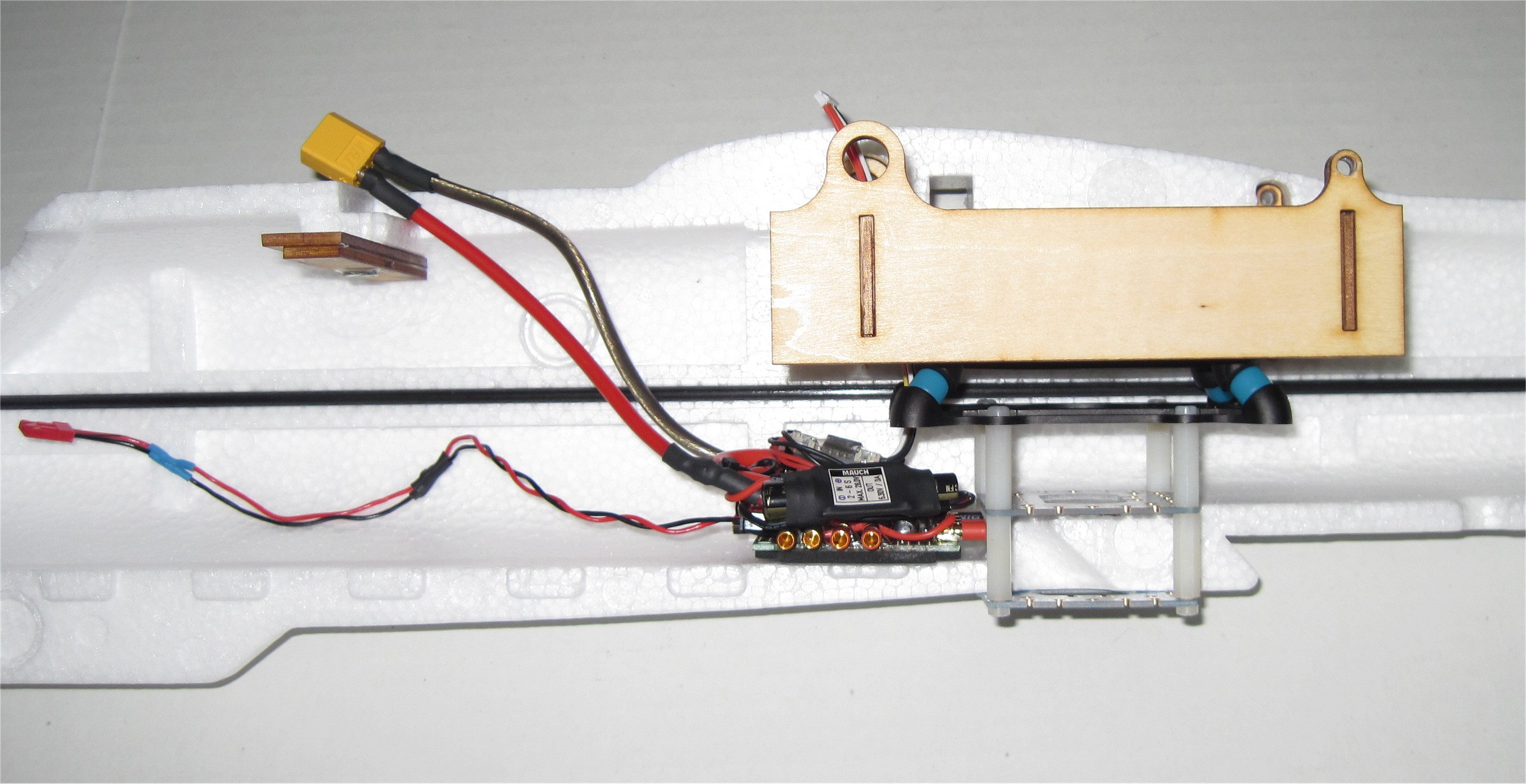
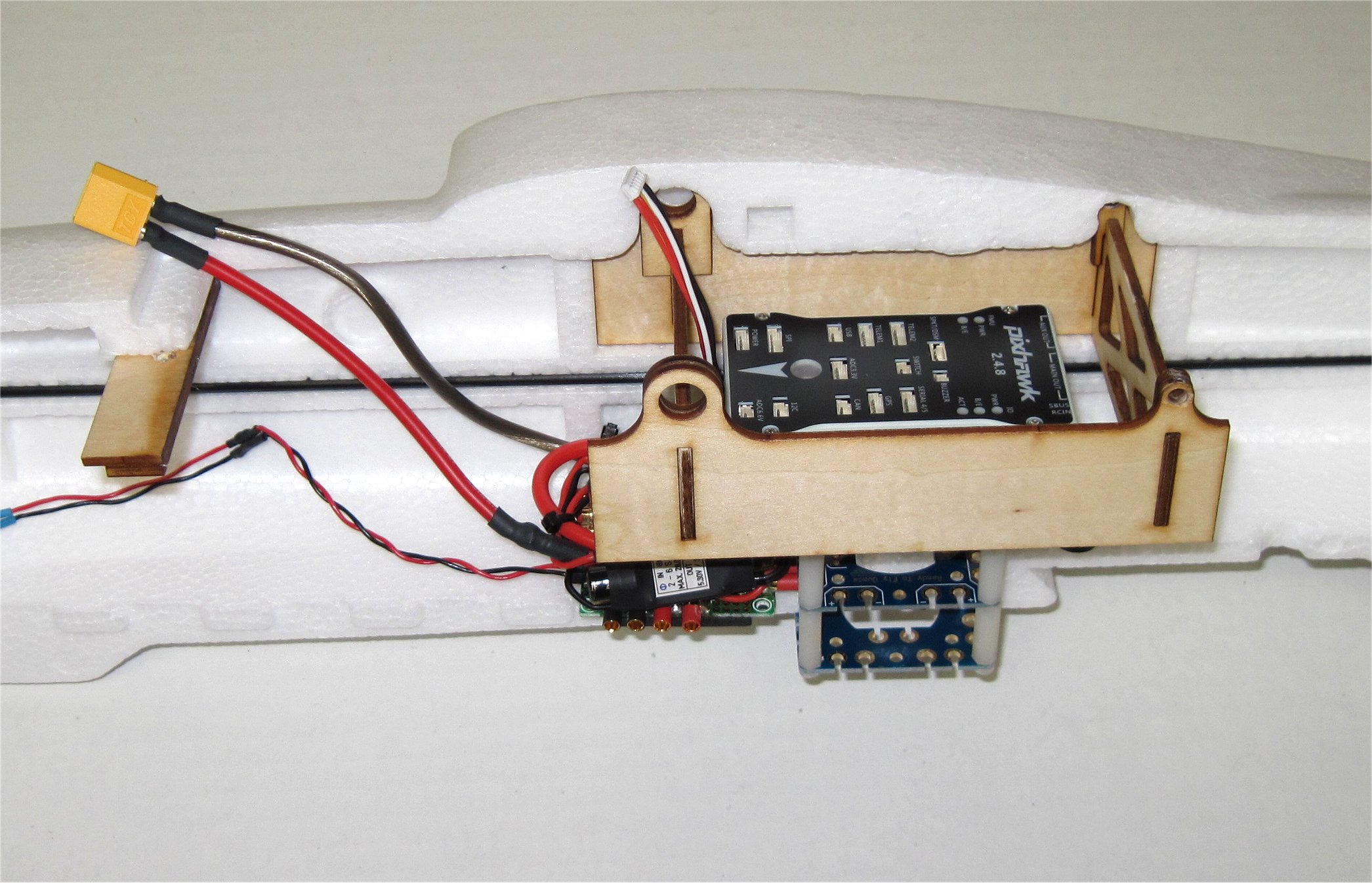
APM Parts
Pixhawk v2.4.8 on eBay
M8N GPS on eBay
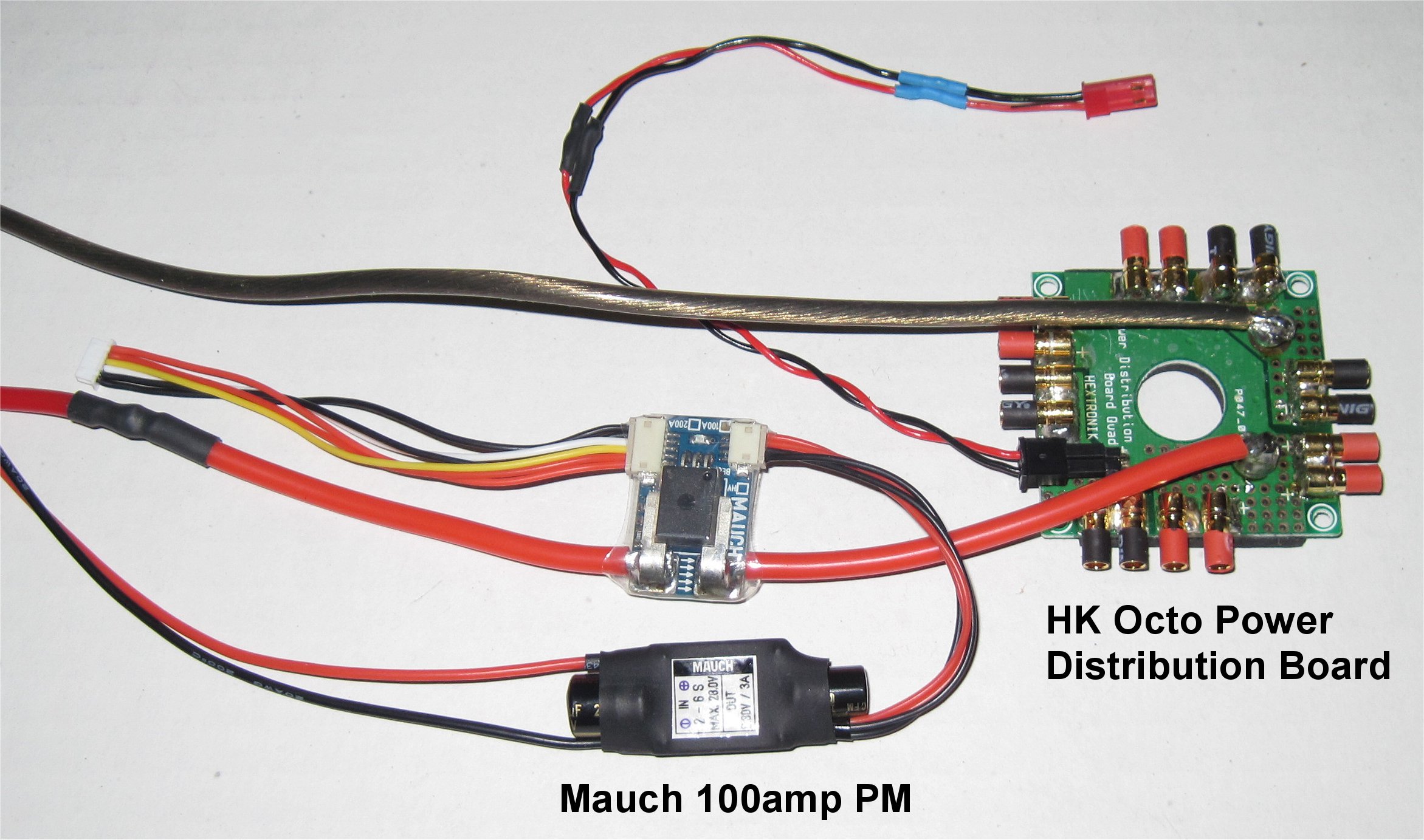
Mauch Power Module - from Craft&Theory
Mauch Company in China - has distribution to many continents
Hobby King Octocopter Power Distribution Board - $5.
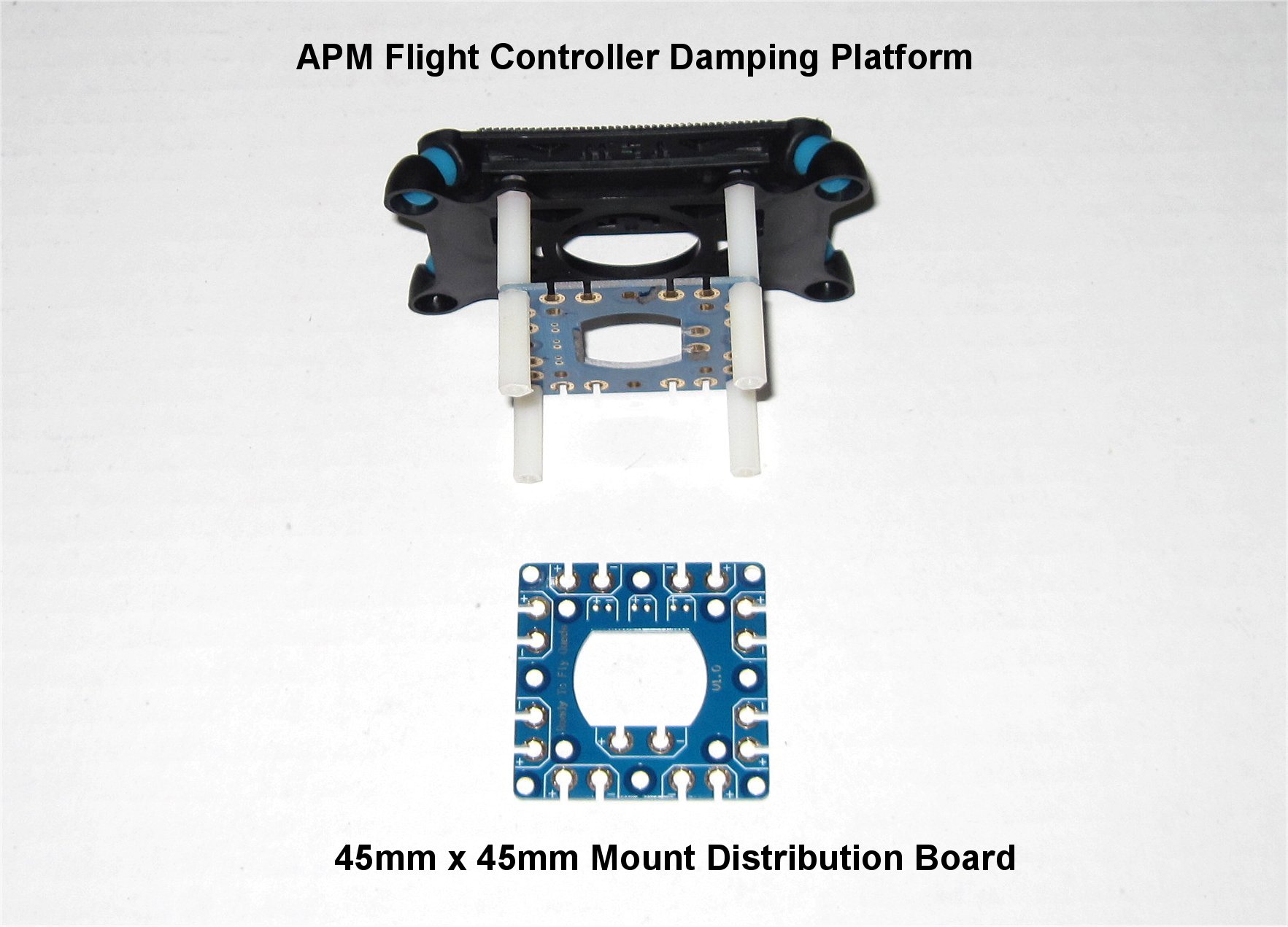
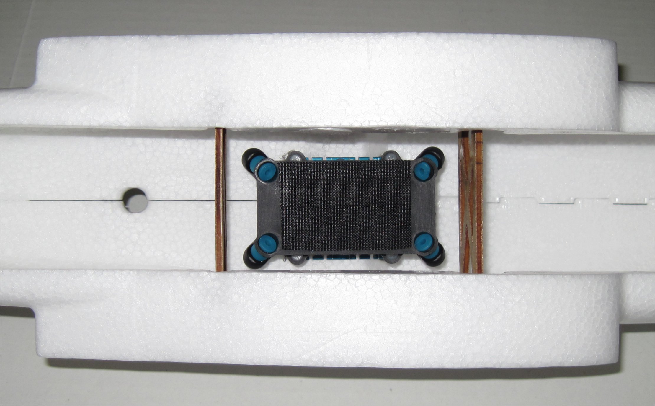
APM Flight Controller Damping Platform - 45mm Mount - HK - $3.35
HK Power Distribution Board - 45mm Mount - HK $2.20
RTFQ Power Distribution Board - 45mm Mount - RTFQ $2

Quad Parts
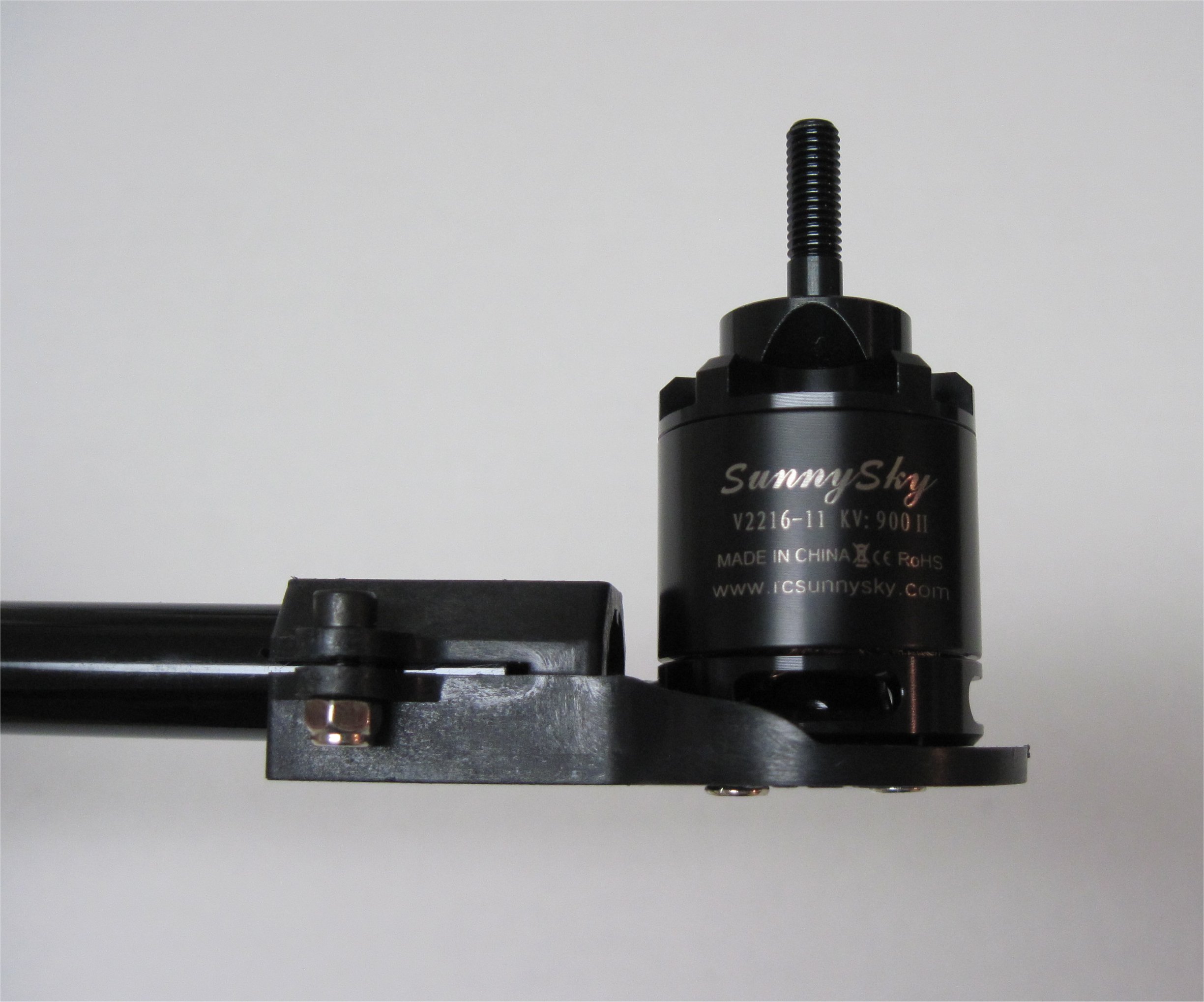
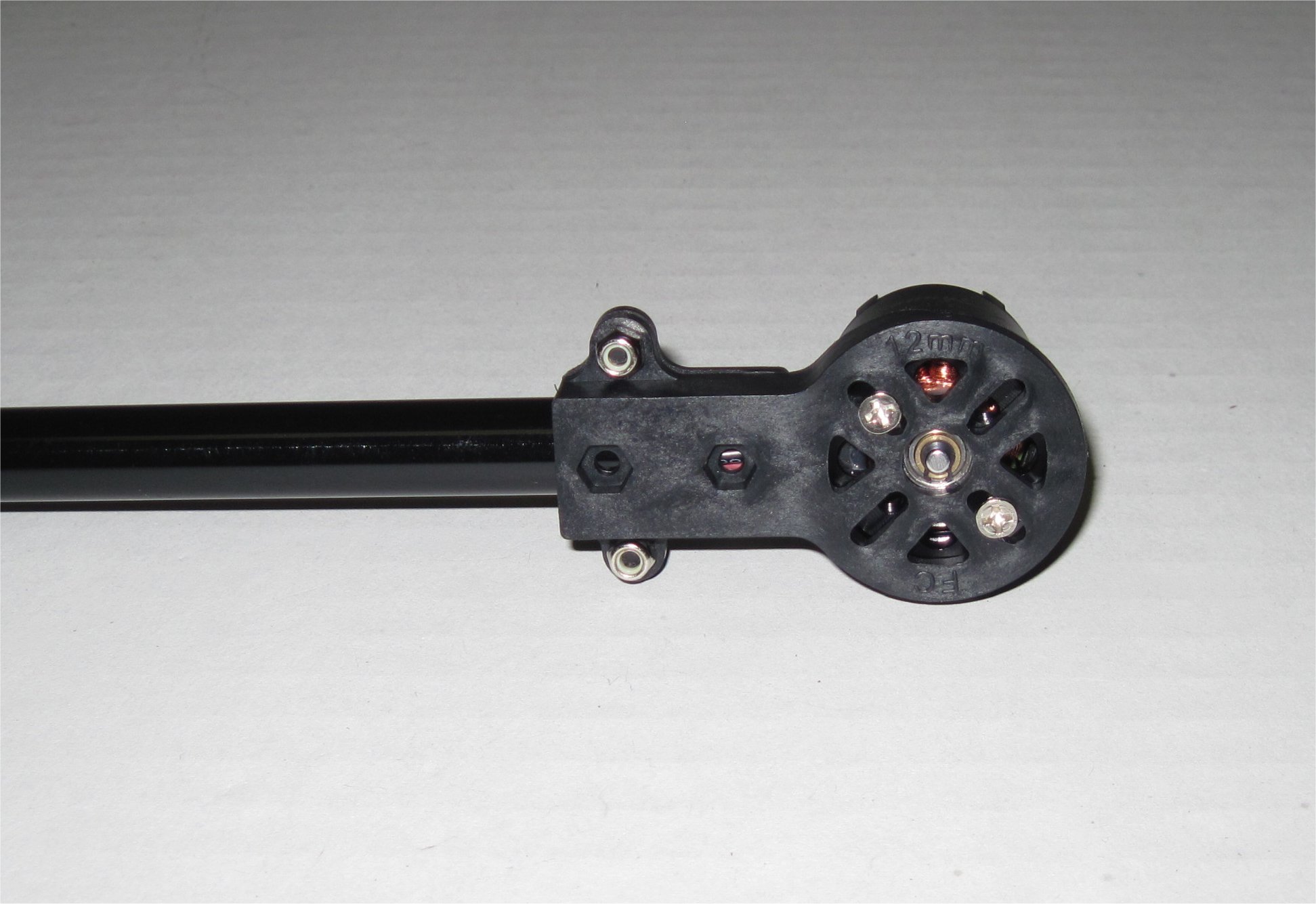
DIY Round Tube Motor Mount (12mm Tube) - HK USA - $1.80 x 4
Carbon Fiber Tube (hollow) 12x750mm - HK USA - $5.11 x 2
SunnySky V2216-10 KV900 Motors - BuddyRC - $16 x 4
Velotech Magic Multirotor Speed Controller 30A with SimonK Program OPTO - BuddyRC - $8 x 4
HQ Prop 10x5 E Carbon Composite Props - RTFQ - $7/pr x 2

Optional Parts
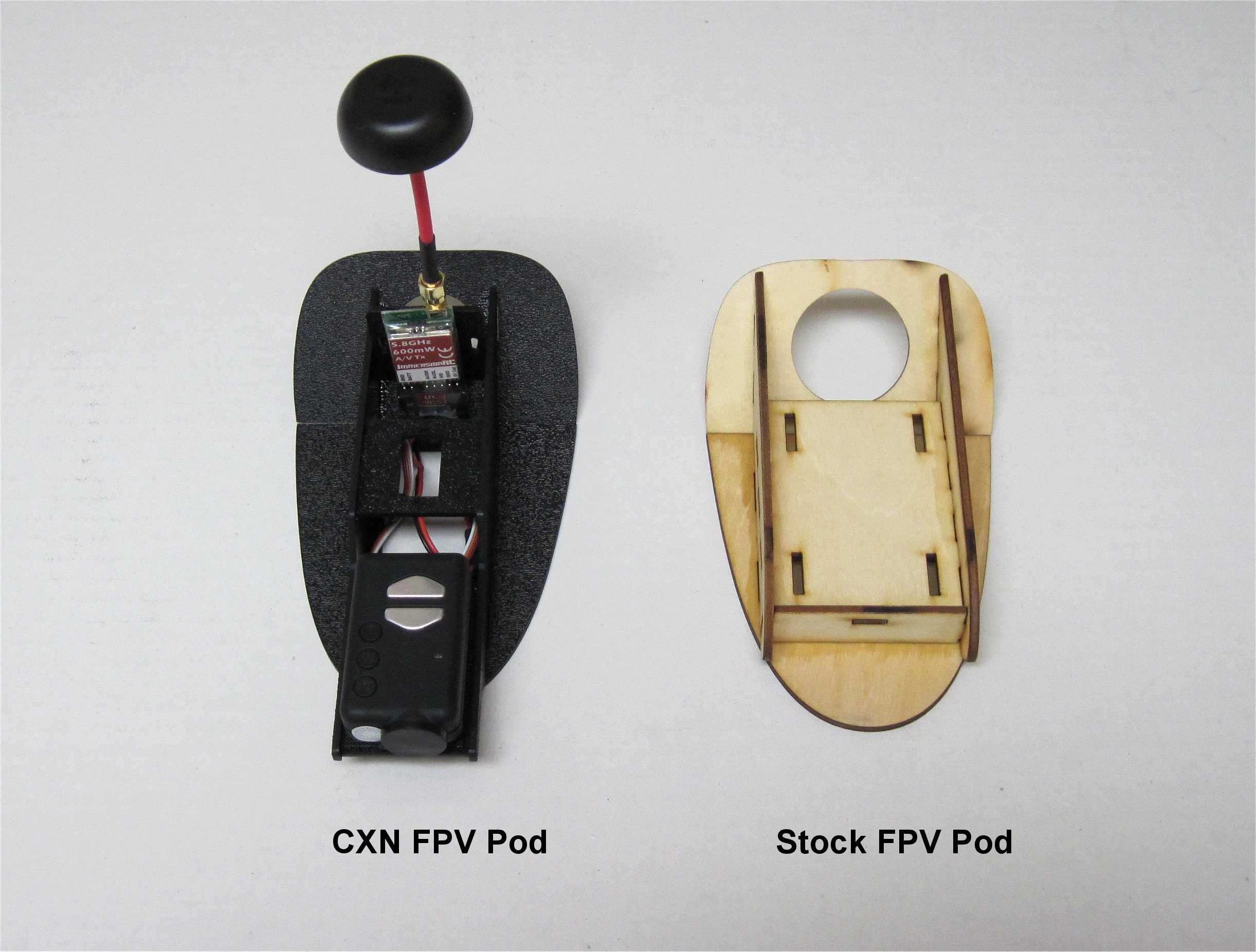
CXN - Mini Talon FPV Pod - RMRC - $25 (optional)

Interesting Links
RC Groups thread on mini Talon FPV
Prop Chart Data for Cobra 2814/16
Mark_Q’s Build #2 Wiki

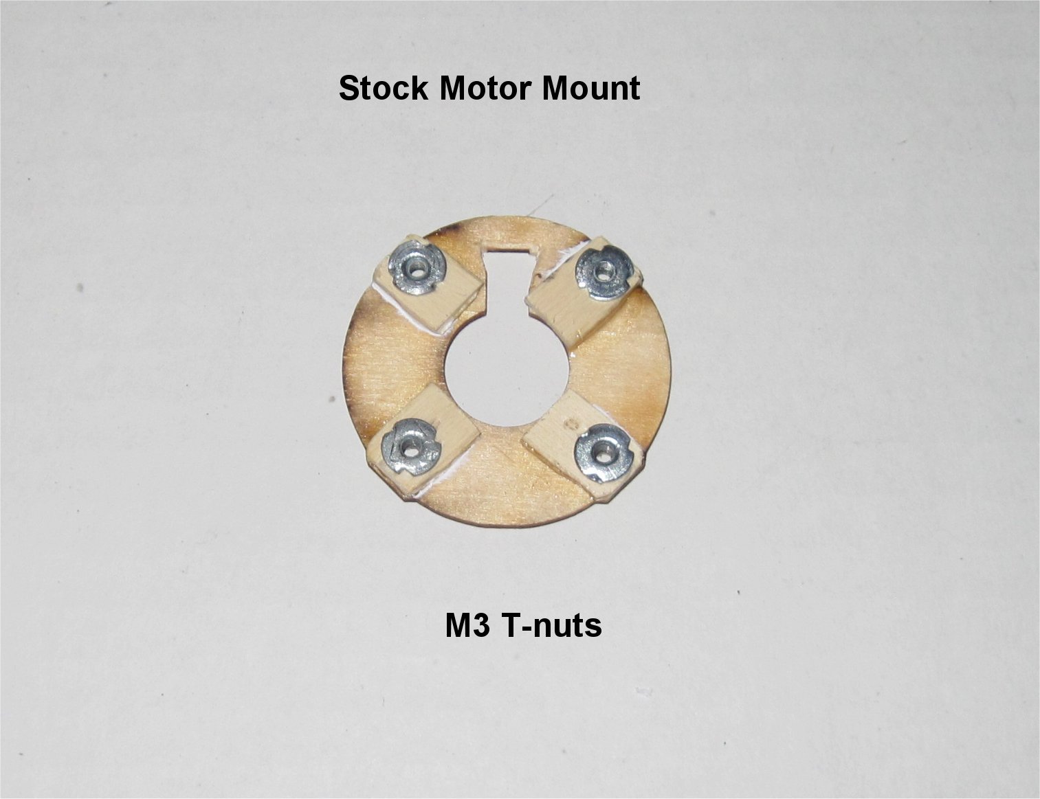
So far, my only modification has been to use M3 t-nuts for the plane motor mount and main hatch. I glued parts into one side of the mini Talon but won’t glue the halves together until I get a good feel for all the component placement.

4 Likes

A couple more build images.

My tail fins are constructed similar to the Mozzie using the stock linkage and press fit with tape servo installation. I spray painted them with Krylon Fusion Red.

My CXN FPV pod will use a Mobius and ImmersionRC 5.8GHz video transmitter. The stock FPV pod will have added weight to match the loaded CXN pod for initial testing without cameras.

1 Like

Good idea :slight_smile:

mine is flying awesome. if you have any questions feel free to ask!

1 Like

Thanks for posting your video. It looks like it flies great and I love the red tail lights!

I see that you mounted your quad bars on the wing. Did you need any reinforcement? It would be great if you could post some photos and list your power system parts like motors, ESCs, props, and Lipo pack.

Cheers!

sure, i will ! sadly on monday im on a weekend trip.
i flew first without reinforcement, but for better yaw behavior i added some later.
will make some pictures to make that clear.

Great! Enjoy your weekend trip. It would be nice if you could post your .param file too. I see that v3.8.0 is now released!

I combined my Mauch 100amp PM with the HK Octo Power Distribution Board to save some space. It will go in the bottom of the fuselage in between the Pixhawk and 4s Lipo up front.

The Sunnysky v2216-11 motor fit perfectly on the inexpensive mount and carbon tube from HK. The long SunnySky motor wires easily fit inside the tube. I was happy with the all black clean look as my HK 10x5 props are also black. The motor mounts also come with optional screws and nylock nuts to drill through the carbon tube but they are not needed. The hold is plenty strong just using the clamp and it allows you to adjust the angle of attack. Sam recommends giving the quad motors about 5-7degrees of forward pitch.

I created a removable electronics platform using 45mm parts and nylon M3 standoffs. Like the 3D printed versions, it makes it easier to access the components, if needed. The Pixhawk is mounted slightly forward to allow space for the servo and ESC connectors.

Note that the bottom air exit of the frame is not blocked. I only needed to drill four holes in the frame for the nylon standoffs. There is plenty of space between the nylon standoffs and the inner side walls to run cables.

Hi Greg,

With the bottom rudder timber insert I’d maybe cut it to half the height before installing. It is very flimsy and can make the bottom rudder warp or snap on a hard landing. Also the Servo cables will be very close to the timber in the fuselage box with the PXH in the center of it, I’d make sure they’re protected from rubbing against the timber. From what I can tell you have the current sensor on the battery input which I really wouldn’t recommend as it’s likely to go over 120A on transition. (BTW the mozzie cable loom is pretty efficient for cable weight/performance, but takes some time to solder together. You can also solder it all instead of using connectors, just makes it harder to repair/diagnose) The timber pieces for the lid are also optional, we just tape the front on and puts some magnets on the rear foam.

Where do you plan on mounting the quad ESC’s atm?

Otherwise looking good :slight_smile:

Hi Sam,

Thanks for the tips! I am quite happy with the precision fit of the timber and foam pieces. I didn’t like the long rudder base anyway, since we are using it as a quadplane, so I’ll cut it like you suggest.

I haven’t decided on the ESC locations yet. My initial carbon tube placement plan is to mimic the Mozzie but I have not yet played with the location using HQ 10x5 props. I’m off to Canada for a week and will be back on the 13th.

The Mauch PM boards are based on the Allegra ACS758 hall current sensors, ACS758-050U for the 50A version, ACS758-100U for the 100A version and ACS758-200U for the 200A version. Even “if” something went wrong with the current board, the Pixhawk analog input is protected as the maximum output voltage of the sensor board is 3,7V limited by the OP Microchip (MCP601) specially designed for microprocessors analog inputs.

Hey,
sorry for the late reply, weekend was a bit longer haha :smiley:

so here are the pictures of the reinforcement:
The CFK rods were glued to two small CFK plates and they were glued to the foam.
My ESCs are mounted under a 3D print housing inside the wings right at the edge of the plates (you can see it a bit under the CFK patch). Thats how the video was made. You can also see the lens of the mapping camera sticking out of the bottom.

The big CFK patch and the CFK rods on the top were added later because i wanted to improve the yaw performance.

the setup:

4s 6600mah lipo
4x 12x5 cfk props with MT3506 650 KV
1x 8x6 APC AT2216 1250kv

Thanks for the images and setup! Are you using a v-tail setup or just elevator on your MT? Can you post your .param file?

I’m up in Canada for the weekend so I am having R/C withdrawal. :anguished:

Cheers!

.param file :sunny:

i use full v-tail. be aware that this file is for 3.8.0 beta!

1 Like

Thanks for the .param file. Note that on new Pixhawks loaded with v3.8.0, the param file needs to be loaded twice as the first time enables the QP parameter and you need to re-boot.

I’m back in the states getting an R/C fix again! I decided to move my HK Octo-distribution board under the Pixhawk as part of the standoff assembly as it uses a 40mm x 40mm mounting scheme. This allows me to use the two front pairs of 3.5mm bullets and the two rear pairs for ESCs. My front quad rotor ESCs will be just to the left of the Octo board and the two rear quad rotor ESCs just behind the main 40-amp forward flight ESC. I am ready to glue the two halfs together. The X8R receiver will reside opposite the RDF900 telemetry unit on the left half with the antennas routed under the mini Talon belly.

thats super interesting, i think i will try that on one of my bigger quadplanes to get a faster transition.
any drawbacks?

1 Like

We’ll see if Sam can comment on the Mozzie setup with the forward pitch.

How did you connect your servos and ESCs to the Pixhawk? Does the V-Tail split between Pin 2 and Pin4 normally meant for Elevator and Rudder?

  1. Aileron
  2. Elevator (Left V-Tail)
  3. Throttle
  4. Rudder (Right V-Tail)
  5. Front Right QP motor
  6. Front Left QP motor
  7. Rear Left QP motor
  8. Rear Right QP motor

Edit: I added the Bold text based upon the APM Wiki.

There are a few general considerations that need to made for a good quadplane design.

The reason to tilt the hover motors forwards, and why we do that and have used it successfully, is that any positive increase in the angle of attack of the main wing will produce stabilizing lift in hover, especially in wind, whilst using the forward motor assist for position hold. Having a negative wing AoA, which is typical for how normal quads work to fly forwards, adds considerable extra load on the quad motors that can cause them to fail, overheat and at a minimum use excessive power simply to overcome the wings negative lift when pitched forward in quad forward flight.

Accordingly, to overcome this, the quad motor AoA should be a few degrees more than the normall AoA of the wings in forward flight. Typically most wings by design stall at the tip and not the root of the wing causing the aircraft to roll in the direction of the tip stall. Using quad assist means that the main wing cannot stall and roll towards a wing tip, because the quad motors provide attitude control (roll) beyond what the wings surfaces are capable of at low airspeeds. This means that the wing can operate at much higher AoA than is usually the case without quad motors, and the added AoA results in much better low forward airspeed wing lift.

This applies to flying in wind as well whilst the airframe is stationary to the ground position, to the point that with forward motor assist on for position hold, increasing wind reduces the quad motor power requirement to position hold significantly, to the point (about 14m/s and above for the Mozzie) the quad motors turn off and the airframe remains stationary relative to the ground. (I’ve flown it in 80kmh winds). The reason for this is fairly obvious in that wings are subject to airspeed not ground speed, and having a positive AoA at all times allows them to always contribute lift.

A quadplane should never be flown forwards using the quad motors alone, like a normal wingless quad. It should always use the forward motor for forward flight instead.

The only real issues with tilting the quad motors forwards is their affect on forward flight performance, and this relies heavily on the quad propulsion layout and design. Using larger quad props with a forward tilt angle will likely increase the forward cross section of the aircraft, and can result in significant unwanted auto-rotation of the quad motors and props, which in turn will generate unwanted lift and drag in forward flight. The wings are much more efficient at producing lift in forward flight and should be allowed to do so. There are also some secondary effects of having larger props, and spinning props, in that they can cause significant disruption of laminar airflow across the wings which reduces forward efficiency as well. Hence our desire to reduce the prop and motor size to the bare minimum to improve forward flight.

If using larger props that want to spin on forward flight, I’d strongly recommend using the ESC brake function to stop them. Using larger quad props not only interferes with the aerodynamics it can also cause side effects (voltage spikes etc) on the drivetrain depending on how good your ESC’s are or how they are configured. There are only a few ESC that will use a encoder to stop them in the right position for forward flight, so the best way is to simply not use large props. :slight_smile:

3 Likes

Hi Greg
The PWM output configuration looks about right. The V-Tail setup can be a pain sometimes to get right, so I just plug the servo’s in as you have shown and then merrily cycle through the V-Tail param until the control surfaces do the right thing.

Sam,

Thanks for the explanations on the effect of forward pitch, larger props, and v-tail setup. I found a good write-up in the Wiki last night. Perhaps it is new.

APM Plane V-tail Configuration

I now see that my 10" quad props are quite large when mounting across the body but seem ok when mounting on the wing bottom. I will still use them on my first setup and see how it works. If I have problems then I can swap out the hover motors or change the forward flight motor for a 6s Lipo.

The mini Talon is smaller than I expected so it really helped to set things up before gluing the two halves together. I used Foam-Tac to glue the halves together and it worked great!

Cheers!

NP Greg.
That Vtail setup looks good, will have to add that to the Mozzie docs links. :slight_smile:

I think you should be ok with the 10" props, so long you mount the arms across the fuselage and not on the wings. Just use the ESC brake if they spin. I hope to get back to flying one weekend sometime, we seem to have storms every weekend atm, had 100kmh winds 3 nights in a row last weekend. Not ideal for tuning params…

Also I’d advise on the hover maiden to do some temp tests on all your motors/ESCs after 30, then 60 sec, then 3-4 minutes. That will avoid running into any unforeseen thermal problems. I do that on every new propulsions/build I do now after burning through so many motors/ESCs. :-/