Hi everyone,
I’m building a mid-sized rover with two 250W 24V DC motors savaged from old electric scooters.
Being a tank-tread robot, it needs to have skid steering.
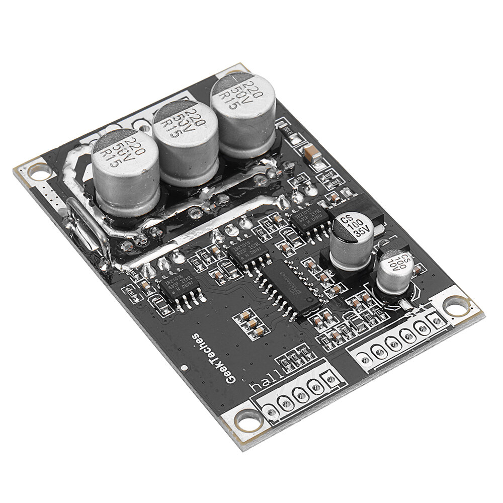
I will use two 6S 5000mAh batteries and two driver boards similar to this one:
I would strongly suggest not to connect the two batteries in parallel. If you need more current than a single battery can provide, get one bigger battery or use two with a single battery per driver board/motor.
Why should he not connect the batteries in parallel?
A bigger battery/lipo usually is more expensive, than two smaller ones.
A 6s 10000mAh pack costs around 200€ from gensace or SLS.
I usually use the same 2S hardcase packs for all of my rovers and connect them in series or parallel just as needed for the rover, motors, electronics. One pack costs 14€ and if one fails, it is no big deal to replace it.
You will not have much fun with those motor controllers. Pretty much the only thing that speaks for them is the low price. They have poor starting power, despite being sensored, poor braking, no regenerative braking. If the braking current gets to high, it will shut off, leaving the motor to spin freely (can be dangerous). You just have a black box, you can not adjust anything. Before wasting money on these bad controllers, I would buy two VESC or an Odrive. More expensive, but worth it.
You need to pay attention to the motor type you plan to use and the ESCs you are going to need.
The first one you posted is a brushless controller with hall sensor input. The second one is a brushed motor controller. A brushed motor will need a brushed controller and a brushless motor a brushless controller. A brushed motor usually has two cables coming out of it and it runs as soon as it is connected to a battery. A brushless motor usually has three cables (or more) and it will only run with a matching (brushless) controller. It is, in some cases, possible, to use a brushless controller as a brushed controller, but not the other way around.
Regenerative braking just means, that everytime your vehicle brakes/decellerates, the excess kinetic/electric energy is fed back into the battery and not wasted as heat in the ESC.
Actually both the first and the second one should be for a brushed motor.
I’m using the MY1016 24VDC 250W motor taken from an electric scooter.
This last driver board seems suited for the job.
Regarding regenerative braking, is it safe for both LiPos and NiCd?
Lipos can take more amps while braking, but the Vescs for example, allow it to configure the maximum amps the battery can take. They also check for the max battery voltage and only use regenerative braking, if the battery is not fully loaded.
I would not use NiCd these days. They are just a pain in the backside, with slow loading, low energy density, low discharge rates, memory effect and so on.
Lipos can be a fire hazard if the batteries are put in parallel and they are not at the same level of charge. Basically one battery would charge the other without real controls on the amount of current that is delivered. In most cases you might not have a problem, but you could, at some point, cause a fire. Putting batteries in serial doesn’t pose the same risk. When the circuit is broken in a serial battery system, the current no longer flows. If the batteries are put in parallel disconnecting them from the motors may still allow the batteries to be connected to one another and current can flow between them. I have seen what lipos can do first hand when not treated with care.
Why worry about it, when keeping the batteries separate or just in serial is so simple.
Hey, I’m getting back with another DC low cost motor driver that has been extensively used for mid to large rovers by makers.
It’s the BTS7960 43A H-Bridge Motor Driver.
It uses a double PWM pin for forward and reverse signals. How (and if) can it be wired to ArduPilot?
Thank you
I have used these BTS7960 boards for a rover and they worked very well for me. They are dual half bridge drivers so one board can driver two motors (forward only) or one motor bidirectionally - you will need two of these for a diff drive rover. I had to modify the Ardurover code to get the correct outputs to control these boards. From memory, I used MOT_PWM_TYPE = 3 (BrushedWithRelay) and added an additional pin that provided a complimentary output to the reverse pin. In this config I connected the Pixhawk pwm output to both R_EN and L_EN and complimentary reverse/not_reverse to the RPWM/LPWM pins. This worked well for 6S lipo battery with 24v/400W motors (that peaked over 800W).
Hi! I’m having a hard time with the BTS7960 because of the double PWM pins for each driver. Would be really nice if you could maybe share your custom ardu rover code? Setup is rover with 2 driven wheels (forward and backwards on each wheel with 2 bts drivers)
Thank you
@rick_r - I no longer have this code but would be happy to look at it again. I don’t have anything to test it on so there may be a bit of a process to get it right… From memory it was pretty straight forward though
@jimovonz Quick response! That would be awesome! Was looking at the ardupilot rover code but was a bit overwhelmed Maybe some background information is useful for you. We are working on a 2 wheel drive rover, it is relatively large. 2m* 1.5m*1.5m.We are using the pixhawk 4 with ardu pilot for path planning and control. The rover is going to take measurements on a meadow. Also we are struggling with which software to use: mission planner? Qgroundcontrol. But if I understand it correclty it’s needed to customize the rover firmware to split the 2 PWM signals to 4 signals that go to the BTS drivers? And it’s needed to change a parameter (MOT_PWM_TYPE = 3 BrushedWithRelay?) to get the “normal dutycycle PWM” instead of the “RC PWM”
        case SRV_Channel::k_motor1:
            _relayEvents.do_set_relay(0, relay_high);
            break;
        case SRV_Channel::k_throttleRight:
        case SRV_Channel::k_motor2:
            _relayEvents.do_set_relay(1, relay_high);
            break;
With:
        case SRV_Channel::k_motor1:
            _relayEvents.do_set_relay(0, relay_high);
            _relayEvents.do_set_relay(2, !relay_high);
            break;
        case SRV_Channel::k_throttleRight:
        case SRV_Channel::k_motor2:
            _relayEvents.do_set_relay(1, relay_high);
            _relayEvents.do_set_relay(3, !relay_high);
            break;
This should give you relay 2 as a complimentary output of relay 0 and relay 3 as a compliment of relay 1. This means that one motor will be connected to relay 0 and relay 2 while the other is connected to relay 1 and relay 3.
You may also have to make sure that the additional two relay pins (#2 and #3) are available by setting the RELAY_PINX and the BRD_PWM_COUNT params - see https://ardupilot.org/rover/docs/common-relay.html
Let me know if you have problems compiling the code - I can send you the binary.
 Maybe some background information is useful for you. We are working on a 2 wheel drive rover, it is relatively large. 2m* 1.5m*1.5m.We are using the pixhawk 4 with ardu pilot for path planning and control. The rover is going to take measurements on a meadow. Also we are struggling with which software to use: mission planner? Qgroundcontrol. But if I understand it correclty it’s needed to customize the rover firmware to split the 2 PWM signals to 4 signals that go to the BTS drivers? And it’s needed to change a parameter (MOT_PWM_TYPE = 3 BrushedWithRelay?) to get the “normal dutycycle PWM” instead of the “RC PWM”