esp8266 board. it is also possible to connect usb cord directly, or course.
I use crossfire… It does RC and telemetry over the same link… I’ve flown out several kilometers and it works great.
At some point it switches to a limited mode where you can’t change parameters, but it still sends data back. That range is quite short for me, 50-100 meters, but TBS supports says I should be getting 1-2k w/ the full telemetry link. I’m working w/ them to solve that…
But anyway, crossfire is a great option for telemetry and RC.
1 Like
Couldn’t the pixracer board fit in the OWL3" frame ? have you tried ?
(it would be lighter and more compact as it integrates the ESP8266 AND contains all IMUs including a mag)
Pixracer dimension and weight:
Weight: 10.54g (.37 oz)
Width: 36mm (1.42”)
Length: 36mm (1.42”)
and the Kakute F7:
Size:55x40x6.4mm
Weight: 17g
It may fit. I also have one pixracer i received back from repair but did not try fitting it. Owl frame can fit quite a bit as you can use higher posts. But pixracer will not have osd and has less uarts than i wanted. Plus it has imu hard mounted and it also not a good factor. I just like kakute better and it is $50 cheaper. I was curious about that stack and it worked out well. Pixracer would probably also worked out ok.
I am not sure how well an embedded mag on pixracer board will behave right above 4in1 esc module. That may not work out well, i think. The way i monted gps worked out well.
I have 3 Pixracers one on a 210 quad and find the integrated mags useless on all the craft. Also, powering direct from battery as some of these F4 and F7 boards do cuts down on required hardware. And it’s hard to beat a $30 AIO FC. I like PixRacers but the implementation of these small and cheap FC’s with Arducopter is brilliant I think.
2 Likes
I too get very high VibeX on my 180mm 4s. I think it’s down to the props, can’t think of anything else, and my theory is that it’s either propwash or something to do with the relative position and acceleration of each at any one time - I am using 4" BN and they are quite aggressive on 4s relative to the size of the copter. Z has no component in this scenario (which makes me doubt propwash) and Y may cancel each other out better. My FC is softmounted on the rubber matek posts.
I gave up on the ESP8266 that came with my pixracer - way too unreliable and very short range, even with the very latest firmware. Plus it pokes up quite a lot above the board itself. Switched to a bluetooth module mounted underneath and never looked back.
Odd, my esp range is ok for wifi, 50-70 meters. It is more than bluetooth i think. But, BT is a good solution too. What module do you use?
Vibes are odd. I tried to wrap center stack with duct tape - 2 axels went down vibes wise but Y somehow got up to 60. Very annoying.
I use an HC-06 clone - https://hobbyking.com/en_us/multiwii-mwc-fc-bluetooth-module-programmer-android-compatible-1.html
interesting, thx for the info.
i found this article: https://oscarliang.com/best-blheli-32-settings/
and tried it with my blheli32 - altered 24 to 48 for pwm. i see vibes just marginally a bit lower now, like, it went from 44 avg to 35 avg, but, no miracle happened. i also see current curve got smoother, less spikes show, so, will probably keep it for now as that.
on the downside of 48 freq i see mag interference went up to 36% from 18% where it was so auto analysis now fails compass but i pretty much ignore that anyway.
here how center stack looks now - i used matek rubber posts on top and bottom to prevent any wobbling. still, result did not improve much. there is foam in front of imu sensor. sensor sits on the double soft pad.
it simply cannot have vibes that high. yet it has `em.
https://drive.google.com/file/d/1AbSfZHFQr48Fq3ggDKtNJJM8jv4sKg3nog/view?usp=sharing
it is odd. something else is doing it.
it was very windy outside so i could not properly autotune it, but when it loiters in alt hold in-house it is very stable and i hear no oscillations.
just to put those vibes in perspective - here is a same vibes graph from a same kakute f7 FC that sits in my rooster frame - it is set on same matek rubber posts, uses 3 blade 6" props and motors are 2100kv.
owl has 3 blade 3" props on a 3600kv motor. frames are carbon fiber both, proximity from props is also comparable considering size diff of props. it is a samee alt hold loiter inhouse log.
i cannot get it. it is not adding up…
I wonder if you could learn anything with FFT analysis. When I have run this on PixRacer I enabled INS_FAST_SAMPLE (default on PixRacer) and set INS_BAT_MASK to 1. There is a screen in MP to set this also. I played around with it to experiment with notch filtering which I ended up not needing.
i never tried to do that, is there any documetn that describes this process - how to evaluate those screens and adjust notch filter? if there is nothing - can you post couple of screenshots, maybe? how to get to that screen and how to deal with it?
on betaflight there is a plasma tool to see a ton of info about noiseso you can fine tune filtering very precise - here on arducopter i have no clue of where to begin even.
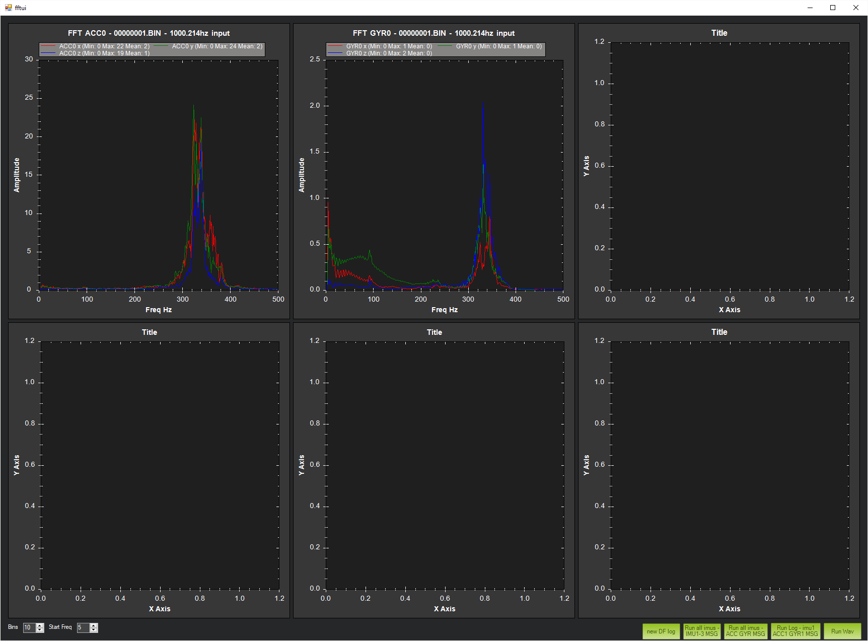
The old way to do it in betaflight was to generate the FFT from the logs. Then the FFT is a graph of frequency, and there should be peaks of noise on the graph. Select the largest peak and use that as the center point of your notch… (unless it’s in the lowpass range… Then choose the next highest peak and use it for the notch)
Dave is replying now, so I’ll quit… I don’t have experience w/ it in arducopter and he does…
I don’t think there is a Wiki entry for it. It was discussed at last years Unconference on this video. FFT stuff starts at 16:38

Peter Barker added some helpful tips on this thread:
In general set the IMU batch sampling from the FFT tab in MP. Then after recording some logs use the Ctrl-F menu in MP, select the FFT button and then load the logs for analysis. How this will function with an F7 board I can’t say.
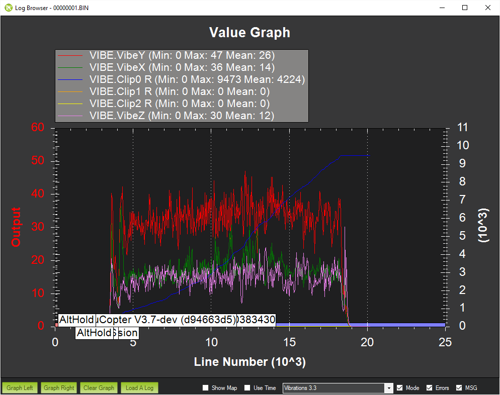
i am confused with what i am seeing. first picture is from the owl with high vibes i posted earlier - goes up to 45-50 in graph vibes 3.3
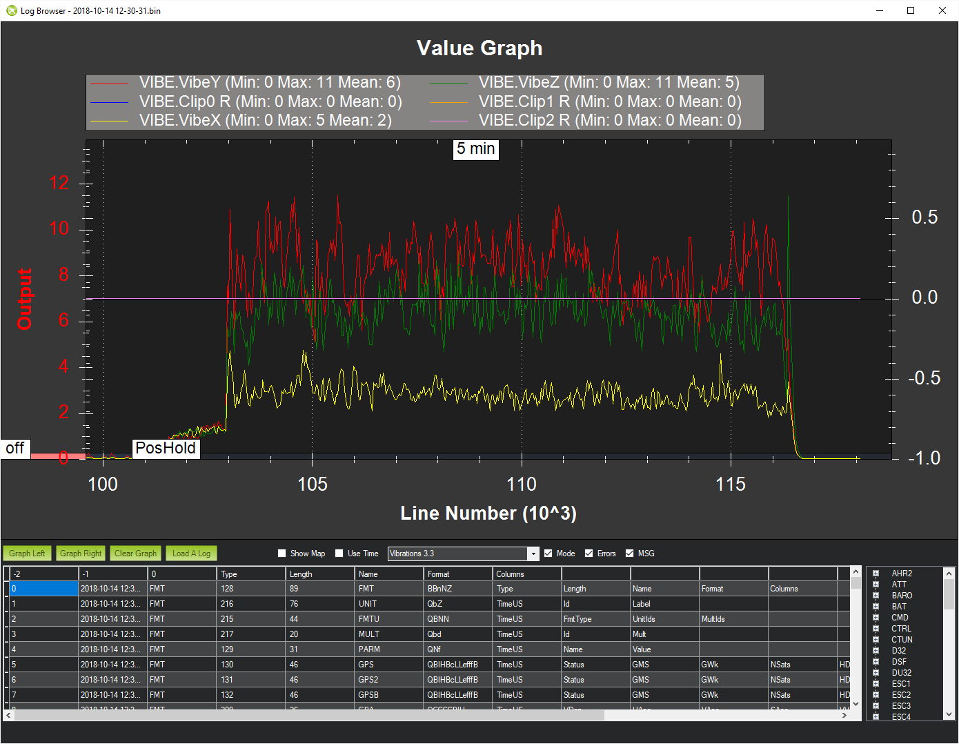
and this second picture is from the chameleon where vibes 3.3 graph is under mark 8. what does it mean?
the first picture, gyro graph - does it mean that an optimal readout spot is around 200hz area where curve goes down? or what is the point of it anyway, sorry, i did not have time to watch the video.
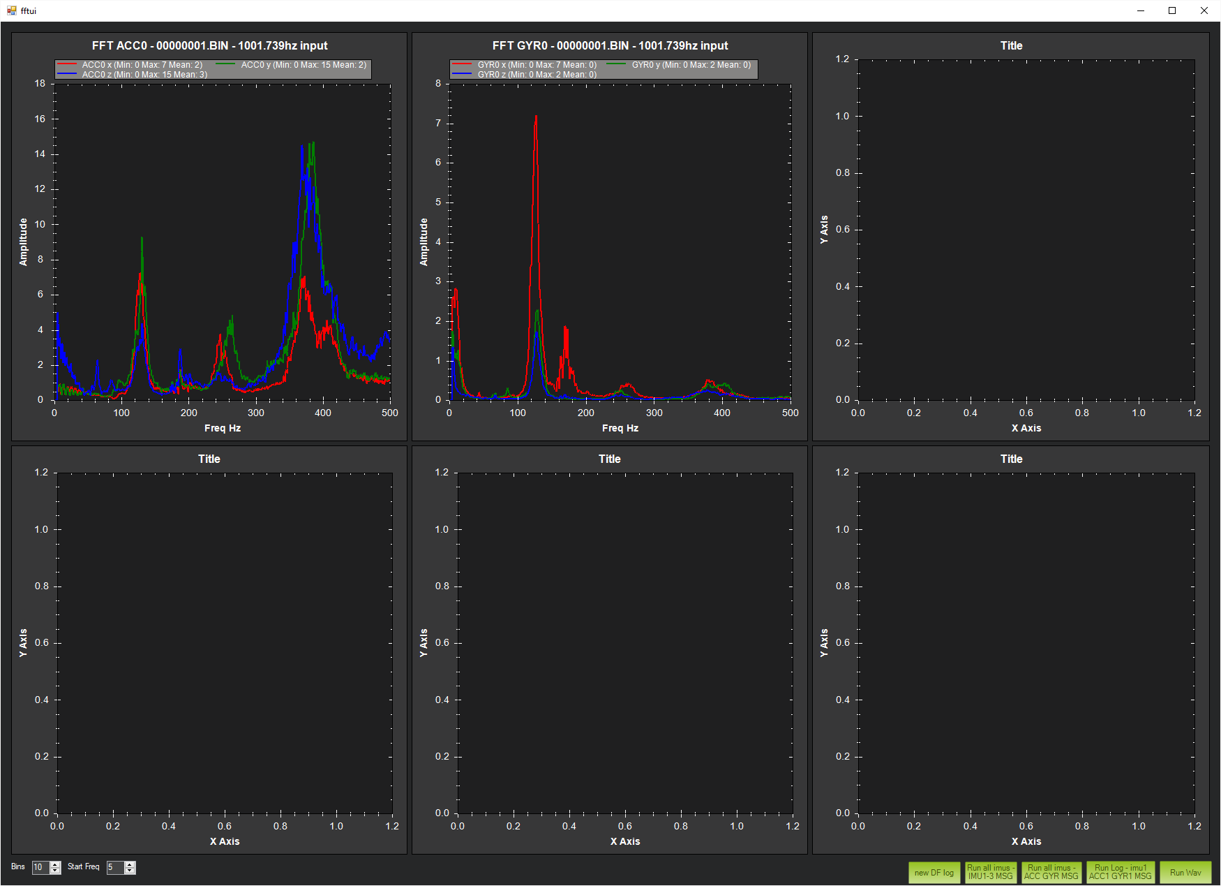
I’d say you want the notch frequency to be 350hz.
I don’t know the details for the rest of the settings…
My best guess would be bandwidth of 100 (I don’t know if they mean bandwidth on each side of the set point, or total bandwidth)
Amplitude… Not sure if I should be looking at the acc or gyro readout… One only needs 2, while the other needs about 25.
I’d go w/ Freq 350
Bandwidth 100
Amplitude 20
And see what happens 
I have no experience, w/ it, though.
I wish I could log a flight! This would be fun to play with. Hopefully someone gets the onboard flash working on these boards.
i do not think arducopter even does not have a notch filter… or does it? i am not sure. would be great to know.
i am surprised on what happens with those tornado t1 motors. they have really strong magnets - you can barely rotate motors… may be it is why it vibrates - not sure.