here how center stack looks now - i used matek rubber posts on top and bottom to prevent any wobbling. still, result did not improve much. there is foam in front of imu sensor. sensor sits on the double soft pad.
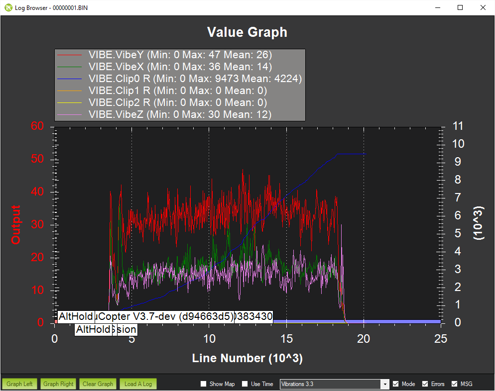
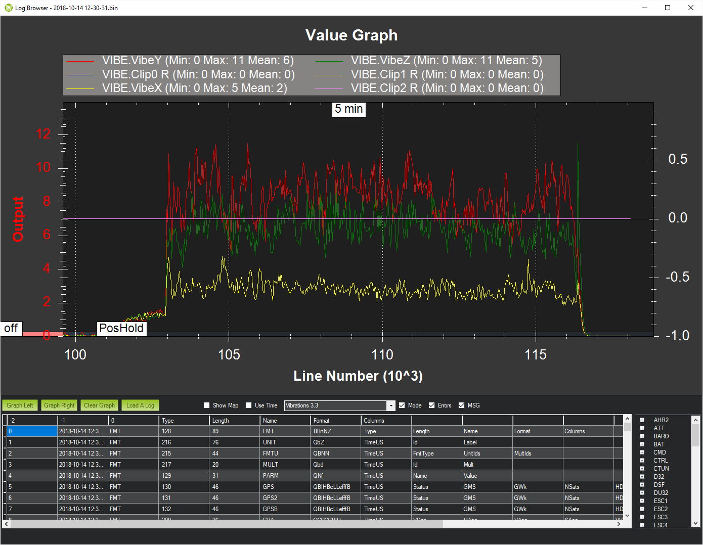
just to put those vibes in perspective - here is a same vibes graph from a same kakute f7 FC that sits in my rooster frame - it is set on same matek rubber posts, uses 3 blade 6" props and motors are 2100kv.
owl has 3 blade 3" props on a 3600kv motor. frames are carbon fiber both, proximity from props is also comparable considering size diff of props. it is a samee alt hold loiter inhouse log.
i cannot get it. it is not adding up…
I wonder if you could learn anything with FFT analysis. When I have run this on PixRacer I enabled INS_FAST_SAMPLE (default on PixRacer) and set INS_BAT_MASK to 1. There is a screen in MP to set this also. I played around with it to experiment with notch filtering which I ended up not needing.
i never tried to do that, is there any documetn that describes this process - how to evaluate those screens and adjust notch filter? if there is nothing - can you post couple of screenshots, maybe? how to get to that screen and how to deal with it?
on betaflight there is a plasma tool to see a ton of info about noiseso you can fine tune filtering very precise - here on arducopter i have no clue of where to begin even.
The old way to do it in betaflight was to generate the FFT from the logs. Then the FFT is a graph of frequency, and there should be peaks of noise on the graph. Select the largest peak and use that as the center point of your notch… (unless it’s in the lowpass range… Then choose the next highest peak and use it for the notch)
Dave is replying now, so I’ll quit… I don’t have experience w/ it in arducopter and he does…
I don’t think there is a Wiki entry for it. It was discussed at last years Unconference on this video. FFT stuff starts at 16:38
Peter Barker added some helpful tips on this thread:
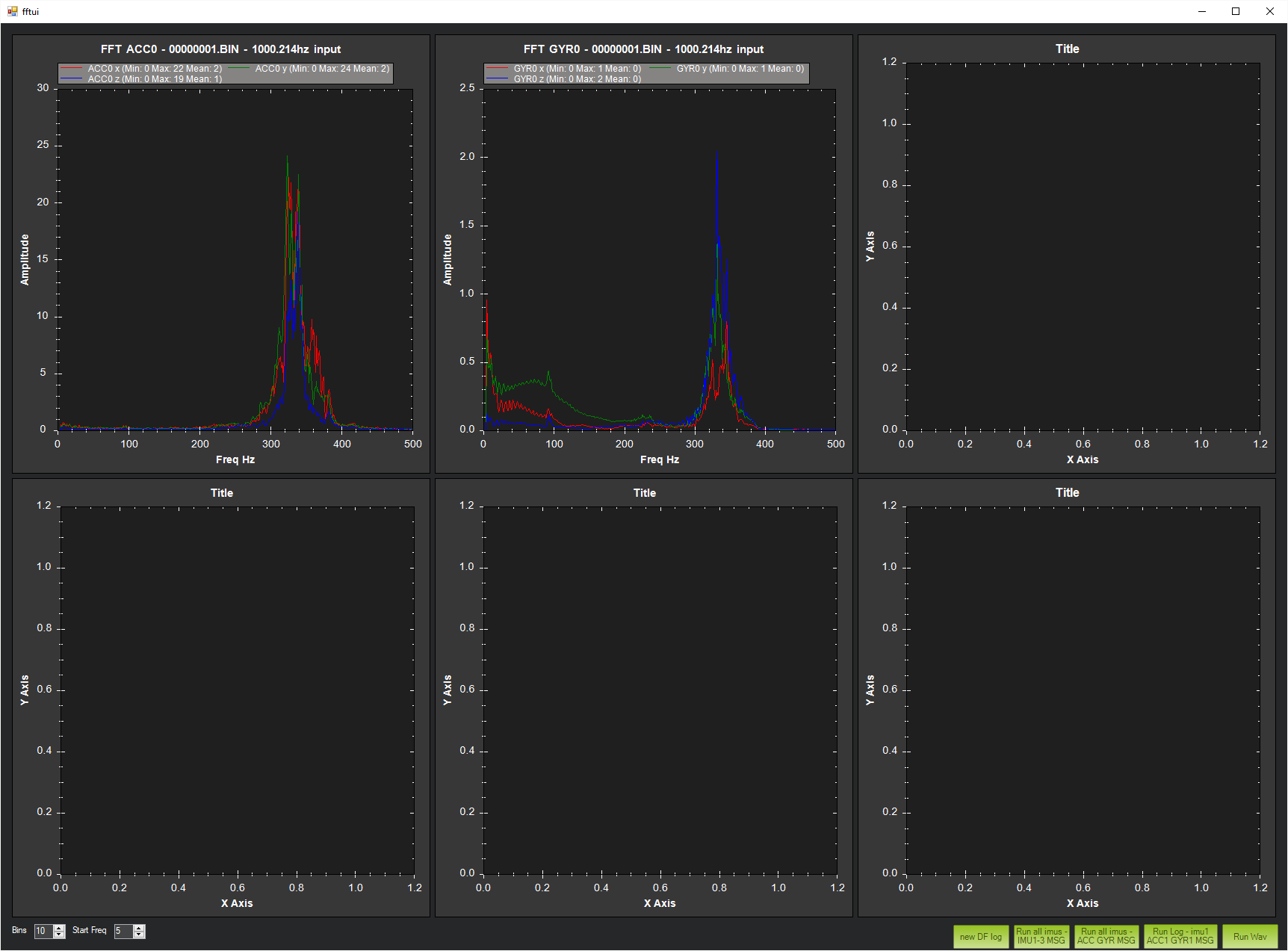
In general set the IMU batch sampling from the FFT tab in MP. Then after recording some logs use the Ctrl-F menu in MP, select the FFT button and then load the logs for analysis. How this will function with an F7 board I can’t say.
the first picture, gyro graph - does it mean that an optimal readout spot is around 200hz area where curve goes down? or what is the point of it anyway, sorry, i did not have time to watch the video.
I’d say you want the notch frequency to be 350hz.
I don’t know the details for the rest of the settings…
My best guess would be bandwidth of 100 (I don’t know if they mean bandwidth on each side of the set point, or total bandwidth)
Amplitude… Not sure if I should be looking at the acc or gyro readout… One only needs 2, while the other needs about 25.
I’d go w/ Freq 350
Bandwidth 100
Amplitude 20
And see what happens
I have no experience, w/ it, though.
I wish I could log a flight! This would be fun to play with. Hopefully someone gets the onboard flash working on these boards.
i do not think arducopter even does not have a notch filter… or does it? i am not sure. would be great to know.
i am surprised on what happens with those tornado t1 motors. they have really strong magnets - you can barely rotate motors… may be it is why it vibrates - not sure.
Freq=350
ATT=15? (This is the amount the filter attenuates… You might need 20 or 25… I’m not exactly sure how to interpret the logs)
BW=100? (This is the bandwidth, but I’m not sure of the details… It looks like you need just over 100hz to null out that spike… But the other couple examples of people using notch filters I’ve seen are only using around 10hz… But their noise spike was much thinner, too)
Enable=1 (I think 1 generally means to enable)
But, I have no experience… Maybe Dave or someone who has actually tried it will post at some point.
I would imagine if you have the filter enabled, then the vibe reading and the FFT will show you the post-filtered results, so you should see a change in the vibe and fft graphs. But again, I am not positive as I’ve never tried it…
I need flash logging on this omnibus nano!!
thx - i am trying it now… as of omnibus nano - i do not like it, it is just too limited. i hope may be matek will make new better controller soon, will see.
from other perspective - a 20mm mount, but, still, too limited.
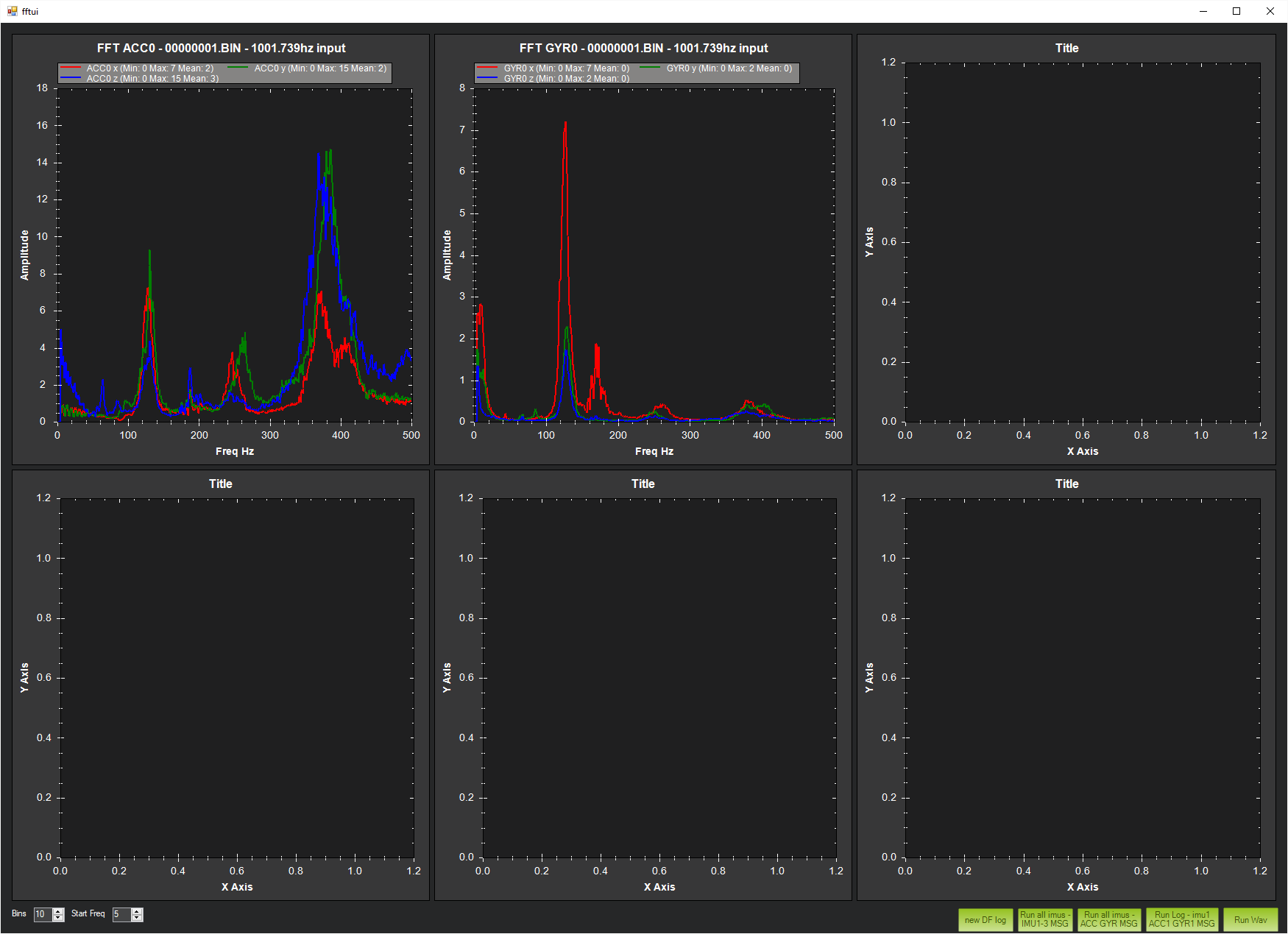
interesting, the ins_notch_freq in MP has a top limit of 200. i used value of 350, will try to fly it now and look at log.
soo, a result is rather discouraging. with a center freq set to 350, notch_bw to 50hz, notch_att to 15 db it flips over at takeoff and refuses to fly. turning it off makes it work fine. i will try to reduce those params but i do not have a god feeling about it. it is not an effect a notch filter would be expected to produce…
and i just grepped whole arducopter code base for ’ INS_NOTCH’ word and it found nothing. will try asking at dev channel - i would like to see where is it coded.
Sorry Paul I played around with it just enough to be dangerous and I wasn’t really chasing a problem just experimenting. I wonder whether a frequency that high can really be accomplished with the loop rates running in Arducopter. Asking in the DEV thread is a good idea, I’ll be interested in the feddback you get. Here is some additional info on Batch Sampling. http://ardupilot.org/copter/docs/common-imu-batchsampling.html#common-imu-batchsampling
yeah, i will see what will transpire. all i can tell so far - any setting i tried to use has produced an immediate flip-over upon an attempt to liftoff. so i keep it disabled for now.
only good news so far is that tridge may get to the uart driver some time soon, it would be nice to get inversion done i the driver code.
as far as I know (Unless someone has very recently added another 20x20 FC to the list) the smallest FC is still the omnibus nano.
ESC will vary, depending on what you need. Ori32 is small, but heavy. Something like a racerstar (or other random esc) that’s only 10-12A or so will be lighter.
I don’t know about complete pre soldered stacks, but that’s really not important… ESC’s are just 4 or 6 or so wires to connect.
What’s in your “stack” ? The FC this thread is about, Omnibus F4 nano V6, is 5 grams and it includes OSD, battery power in and a couple of BEC’s for external devices. Paired with a 20x20mm 4in1 (I use an Ori32) and it’s very light.
What wicked1 said about the Ori32 is right. Some of the additional weight comes from 4 large current shunt resistors!
I’d like a “complete” lightest stack including FC, 4 in 1 ESCs, PDB. Also it must have current and voltage measurements (hall effect would be perfect but shunt resistor will do)