If the SRx parameters are set, the FC streams data even if it doesn´t receive a heartbeat, or am I wrong? Why else would anything be displayed with the RSSI_Override enabled?
I´m just trying to understand how everything works.
The TX is pin10 on the Teensy. Will I still be able to use Bluetooth/Wifi connection to MP if the TX Pin is connected?
No, unfortunately you cannot share the FC RX pin. Fact of life. That is one of the reasons we now have an ESP32 version that does WiFi and Bluetooth at the same time.
Is there any chace you would port the code to the RFD transmitter module? It has an ESP8266, which is already implemented in your code. You would only (probably) have to change the pins.
Other option would be to only send heartbeat packets while there is no activity on the FC RX pin. Just thinking out loud…
Hi David, I’m very sorry but I have been engaged elsewhere.
But I have been thinking about your situation, and this is still a guess, but I believe what is happening is this:
The RFD900 uses SiK firmware in the radio. SiK firmware injects a Mavlink message type #109 Radio_Status, which contains the RFD900x RSSI. I’m guessing that “the system” only starts sending #109 when MP connects.
Could you please un-comment #define Debug_Rssi, and post the Debug messages from the monitor. Run it for a while without connecting MP, then connect to MP and lets see what happens to rssi.
Auto RSSI_Source===>  Mavlink from FC #65 RC_Channels: ap_chcnt=14 PWM:  1=1514 2=1515 3=1511 4=1515 5=1053 6=1515 7=997 8=998 9=997 10=997 11=2030 12=1512 13=1513 14=1513  ap_rssi65=0  rssiGood=1
Period ms=701	FrSky in Rssi 0x5F101:  fr_rssi=0 fr_payload=0 //00  00  00  00
Mavlink from FC #35 RC_Channels_Raw:   ap_rssi35=0  rssiGood=1
Auto RSSI_Source===>  Mavlink from FC #65 RC_Channels: ap_chcnt=14 PWM:  1=1514 2=1512 3=1512 4=1513 5=1053 6=1513 7=996 8=995 9=995 10=996 11=2029 12=1510 13=1512 14=1513  ap_rssi65=0  rssiGood=1
Period ms=701	FrSky in Rssi 0x5F101:  fr_rssi=0 fr_payload=0 //00  00  00  00
Auto RSSI_Source===>  Mavlink from FC #109 Radio: ap_rssi109=242  remrssi=242  txbuf=100  noise=94  remnoise=87  rxerrors=80  fixed=0  rssiGood=1
Period ms=710	FrSky in Rssi 0x5F101:  fr_rssi=95 fr_payload=95 //00  00  00  5F
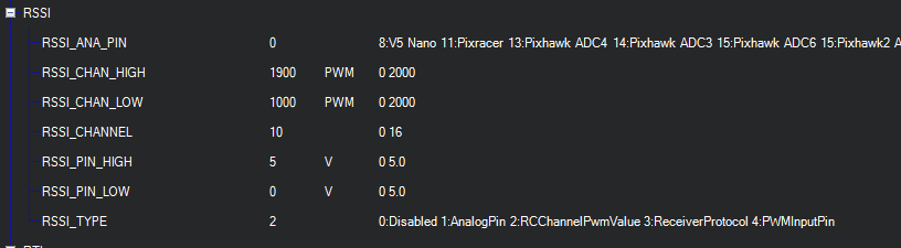
Ok, it looks like that’s what’s happening. You get a good RSSI message only when MP connects. From the #65 it looks like you are using channel 11 for RSSI (11=2028). Have you set up RSSI in Mission Planner? These are my settings (for dragonlink), where I use channel 10
I am not using a pwm channel for rssi, only the 109 mavlink injected rssi values. With the RFD modules (as far as I know) it is not possible to set up a pwm based rssi reporting.
edit. I have spoken with the RFD guys and they told me, that the rssi values only start to get injected, when heartbeat packets are received (so when I connect to MissionPlanner).
Hi David, so your proposal to fake the rssi until MP connects is probably the best option. I actually have a pair of RFD900s that work very well. I just have not played with their settings for a while. Then ULRS and DL settings just confuse matters. You could send me a Pull Request, or I can just do a little patch. Thank you for your valuable input.
I created a pull request (my first one ever) for you. Hope this helps, maybe we should make a #define for it in config.h. RFD specific settings or similar.
Also I have discovered a different issue. While flying the yaapu scipt keeps repeating my current flight mode and sometimes stabilized, even though I don´t have stabilized configured. Also it sometimes tells me “armed” and “disarmed” randomly. Ever encountered this before? Is this an issue with MAV2PT or the yaapu script?
Maybe you didn’t flash the latest? Could you check it out and let me know?
I think it might be useful for non-rfd900 users to also have a dummy rssi as default. It will get overwritten by a true rssi when/if one arrives. The upside is that we don’t always have the confusing “can’t connect” issue. We could make the value easily identifiable, like 66%
Is there any chace you would port the code to the RFD transmitter module ? It has an ESP8266, which is already implemented in your code. You would only (probably) have to change the pins.
Hi David, I flashed mav2pt_v2.54 onto the txmod this morning, using their OTA, and everything seems to work fine. You might need to play around with the S.Port out pin to suit your circumstances.
If you use AP mode the IP will be the same as the txmod.
If you need to re-flash the txmod firmware, simply use the mav2pt OTA.
EDIT: The mav2pt OLED display also works on the esp8266 if you would like to use it.
I compiled using both the Arduino IDE and PlatformIO, using the NodeMCU 1.0 (ESP-12E) board profile. I used D6 for the S.Port, but you could change to any unused pin.
#elif (Target_Board == 4)         // ESP8266 Platform
  #if (ESP8266_Variant == 1)        // Node MFU 12F

    #define MavStatusLed  D0        // Mavlink Status LED
    #define BufStatusLed  99        // None
   //                     D4        // TXD1 - Debug log out
    #define FC_Mav_rxPin  D9        // RXD0 default
    #define FC_Mav_txPin  D10       // TXD0 default
    #define Fr_rxPin      D5        // GP10 SPort - Not used in single wire mode
    #define Fr_txPin      D6        // GPIO SPort - Use me
    #define SCL           D1        // I2C OLED board
    #define SDA           D2        // I2C OLED board
 You could send me a Pull Request, or I can just do a little patch. Thank you for your valuable input.