This is the receiver code. May be helpful?
#include <SPI.h>
#include <LoRa.h>
#include "SSD1306.h"

SSD1306  display(0x3c, 4, 15);

//OLED pins to ESP32 GPIOs via this connection:
//OLED_SDA -- GPIO4
//OLED_SCL -- GPIO15
//OLED_RST -- GPIO16
// WIFI_LoRa_32 ports
// GPIO5  -- SX1278's SCK
// GPIO19 -- SX1278's MISO
// GPIO27 -- SX1278's MOSI
// GPIO18 -- SX1278's CS
// GPIO14 -- SX1278's RESET
// GPIO26 -- SX1278's IRQ(Interrupt Request)

#define SS      18
#define RST     14
#define DI0     26
#define BAND    915E6  // 433E6 866E6  915E6

void setup() {
  pinMode(16,OUTPUT);
  digitalWrite(16, LOW);    // set GPIO16 low to reset OLED
  delay(50);
  digitalWrite(16, HIGH);
  display.init();
  display.flipScreenVertically();
  display.setFont(ArialMT_Plain_10);
  display.setTextAlignment(TEXT_ALIGN_LEFT);

  Serial.begin(115200);
  while (!Serial); //if just the the basic function, must connect to a computer
  delay(1000);
  Serial.println("LoRa Receiver");
  display.drawString(5,5,"LoRa Receiver");
  display.display();

  SPI.begin(5,19,27,18);
  LoRa.setPins(SS,RST,DI0);

  if (!LoRa.begin(BAND)) {
    display.drawString(5,25,"Starting LoRa failed!");
    while (1);
  }
  Serial.println("LoRa Initial OK!");
  display.drawString(5,25,"LoRa Initializing OK!");
  display.display();
}
void loop() {
  // try to parse packet
  int packetSize = LoRa.parsePacket();
  //int pSize = (packetSize / 1e3);
  if (packetSize) {
    // received a packets
    Serial.print("Received packet: ");
 //   Serial.print(" Packet size = "); Serial.print(pSize);
    display.clear();
    display.setFont(ArialMT_Plain_16);
    display.drawString(3, 0, "Received packet ");
    display.display();
    // read packet
    while (LoRa.available()) {
    String data = LoRa.readString();

    long pS = data.length();
    Serial.print(" Packet size = "); Serial.print(pS); Serial.print(" ");
    float snr = LoRa.packetSnr();
    Serial.print(" SNR = "); Serial.print(snr, 1); Serial.print(" ");

    Serial.print(data);
    display.drawString(20,22, data);
    display.display();
    }
    // print RSSI of packet
    Serial.print(" RSSI = ");
    Serial.println(LoRa.packetRssi());
    display.drawString(20, 45, "RSSI:  ");
    display.drawString(70, 45, (String)LoRa.packetRssi());
    display.display();
  }
}
Look at the pins in arduino.h in the variants folder here:
C:\Users%username%AppData\Local\Arduino15\packages\esp32\hardware\esp32\1.0.4\variants
Hi all,
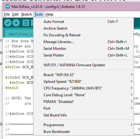
I don’t yet have my wifi kit 32 (still in the mail, thanks corona) but I’m trying to get a head start in learning how to configure m2p. I’ve installed the heltec board definitions as per their guide here but, as per instructions in config.h, there is no “Minimal SPIFFS(Large APPS ith OTA)” option nor is there even a partition option in the tools dropdown.
Is this due to me not having a board plugged in, or have I misconfigured something? I can’t find a single drop of documentation on how to set any of this up for m2p so I’m not sure what was done wrong. Thanks!
EDIT: If anyone else has this issue, here’s (what i think to be) the fix: Use this instead of the heltec definitions.
EDIT 2:
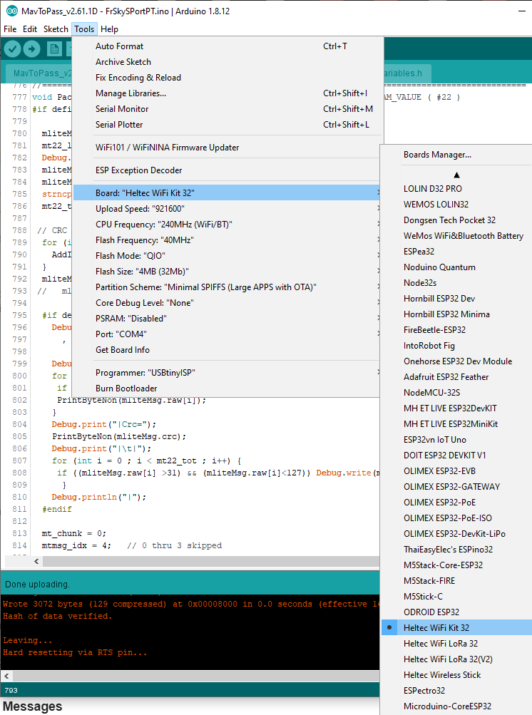
It’s a bit odd that you have “Wifi Kit 32” showing up instead of “Heltec WiFi Kit 32”
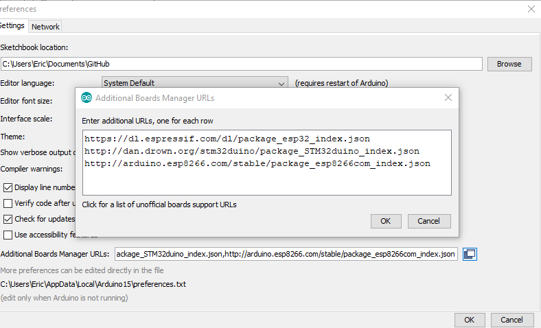
Go to Files, Preferences, and open up the Additional Boards Manager URLs (the icon on the RHS). It should look something like this. The line you are interested in is the d1.espressif.com line
I found the fix for the board definition problem - the heltec-provided board definitions are weird, and using the espressif-provided ones fixed it.
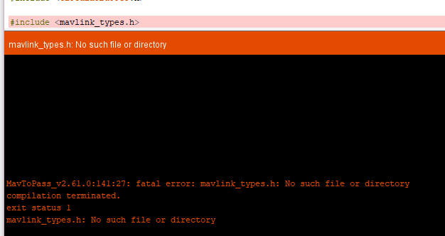
Still having the “mavlink_types.h” error. I’ve copied the libraries folder to /users/me/Documents/arduino/libraries.
Just got my wifi kit 32. OLED says “NO WEB SUPPORT!” and there is no wifi network to connect to.
Running latest version of mav2pass, freshly downloaded.
My exact steps:
copy libraries folder to arduino libraries folder
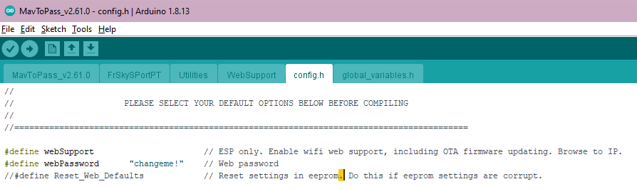
check config.h to be sure that #define webSupport is not commented, and that WiFi_mode is set to 3
make sure board definition is correct
hit upload
Additionally, despite setting #define Relay_Mode and commenting the other two modes, the oled shows ground mode.
yak-54
July 12, 2020, 6:21am
227
After days of playing around with your script i bought you a couple Angola
thank you yak-54 for funding a few more toys to play with
yak-54
July 13, 2020, 10:36am
229
#ifndef Pins_Arduino_h
#define Pins_Arduino_h

#include <stdint.h>

#define EXTERNAL_NUM_INTERRUPTS 16
#define NUM_DIGITAL_PINS        40
#define NUM_ANALOG_INPUTS       16

#define analogInputToDigitalPin(p)  (((p)<20)?(esp32_adc2gpio[(p)]):-1)
#define digitalPinToInterrupt(p)    (((p)<40)?(p):-1)
#define digitalPinHasPWM(p)         (p < 34)

static const uint8_t TX = 1;
static const uint8_t RX = 3;

static const uint8_t SDA = 21;
static const uint8_t SCL = 22;

static const uint8_t SS    = 5;
static const uint8_t MOSI  = 23; to 19 ?
#static const uint8_t MISO  = 19; comment out
static const uint8_t SCK   = 18;

static const uint8_t A0 = 36;
static const uint8_t A3 = 39;
static const uint8_t A4 = 32;
static const uint8_t A5 = 33;
static const uint8_t A6 = 34;
static const uint8_t A7 = 35;
static const uint8_t A10 = 4;
static const uint8_t A11 = 0;
static const uint8_t A12 = 2;
static const uint8_t A13 = 15;
static const uint8_t A14 = 13;
static const uint8_t A15 = 12;
static const uint8_t A16 = 14;
static const uint8_t A17 = 27;
static const uint8_t A18 = 25;
static const uint8_t A19 = 26;

static const uint8_t T0 = 4;
static const uint8_t T1 = 0;
static const uint8_t T2 = 2;
static const uint8_t T3 = 15;
static const uint8_t T4 = 13;
static const uint8_t T5 = 12;
static const uint8_t T6 = 14;
static const uint8_t T7 = 27;
static const uint8_t T8 = 33;
static const uint8_t T9 = 32;

static const uint8_t DAC1 = 25;
static const uint8_t DAC2 = 26;

#endif /* Pins_Arduino_h */
|TFT Driver|ST7789|
what pins do i use for Sport and tx and rx
Let me see if I can set this up for you.
Colin, have you got the display working? Have you set up a working example (not mavtoPass), like here
I see my Lora boards are very different.
Ok, I bought two of these ttgo boards, but delivery will take about 14 days, judging by recent history.
yak-54
July 13, 2020, 11:22pm
233
yes i have works well and even played games on it its very fast
yak-54
July 13, 2020, 11:42pm
234
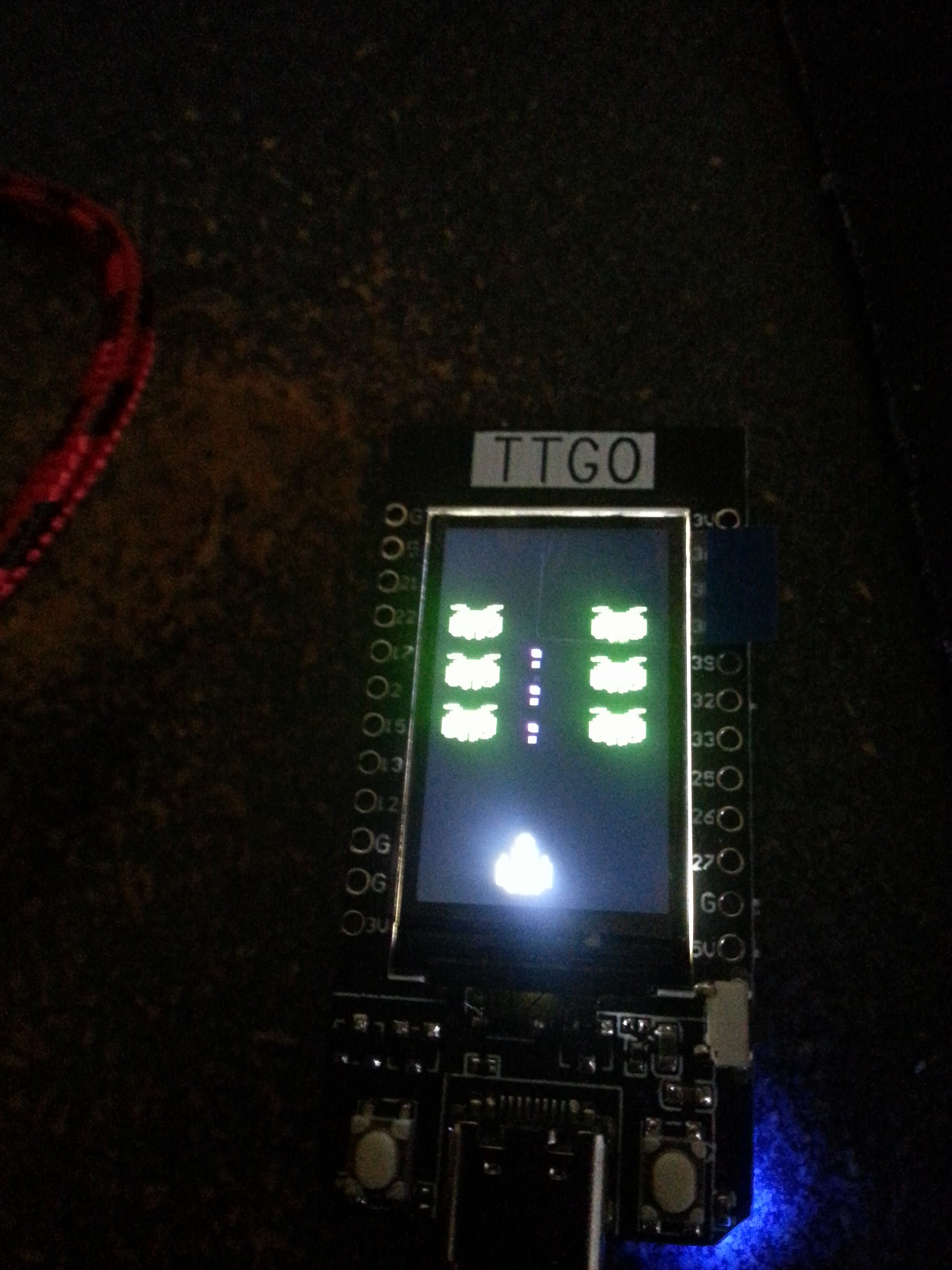
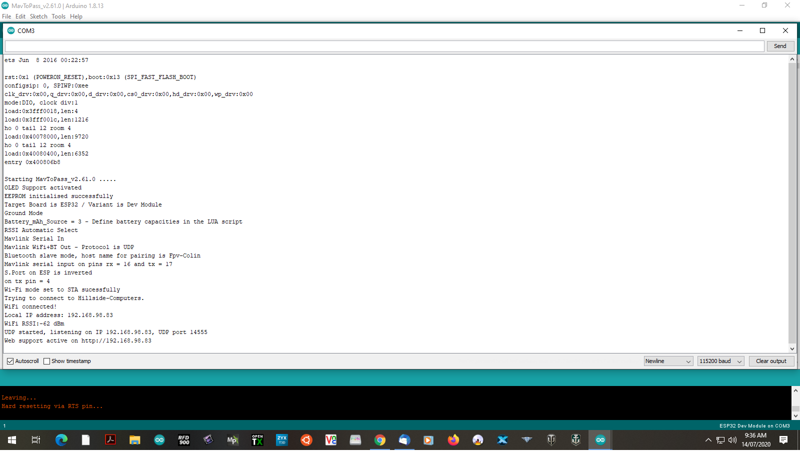
i have upload MtP the wireless and blue tooth are working
![1Untitled|690x388]
Ok, could you try GPIO13 and GPIO14 for S.Port rx and tx? Try ground mode first, with TX only straight into your Taranis. Use a 4.7K resistor in series. It’s a useful safety measure.
yak-54
July 14, 2020, 6:18am
236
will give it go after diner
Hi Eric,
I have been testing a lot lately on the TXMOD and sometimes after 10 min, sometimes after an hour, the converter just stops working. Wifi gets disabled and there is no communication on the s.port and tx lines. The led goes from solid to blinking and the reset button on the outside does nothing. After triggering the reset pin on the ESP it reboots and everything starts working agaon normally. While this happens I still have control over the aircraft, just no telemetry at all. How can we solve this issue?
yak-54
July 14, 2020, 10:52am
238
no gpio 14 pin on this unit
yak-54
July 14, 2020, 10:54am
239
which version are you using ?
I´m currently using v2.60.2