object avoidance is always one of the interesting option in multirotors and now we can see this option in DJI Phantom series.
but most of the time they are expensive for example one of them are TeraRanger Tower Evo starting from 445 $
in this post we will make an object avoidance system with 5 HC-SR04 ultrasonic sensor and one arduino nano.
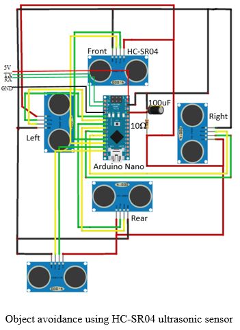
As shown above, five inexpensive ultrasonic sensors HC-SR04 were used for object detection in the front, right, rear, left and down direction. Arduino microcontroller acts as the processor for the receiving sensor data and generate responses accordingly. Arduino Nano was used because of its small size and relatively lighter weight. The Arduino connections with all sensors were sketched and the complete circuit diagram was drawn.
the system was connected to the FC through the telemetry serial port. 5V and ground completes the supply circuit to power the Arduino Nano, while Transmitter (TX) pin of the FC was connected to Receiver (RX) pin of Arduino Nano. Similarly, RX pin of the FC was connected to TX pin at the Arduino.
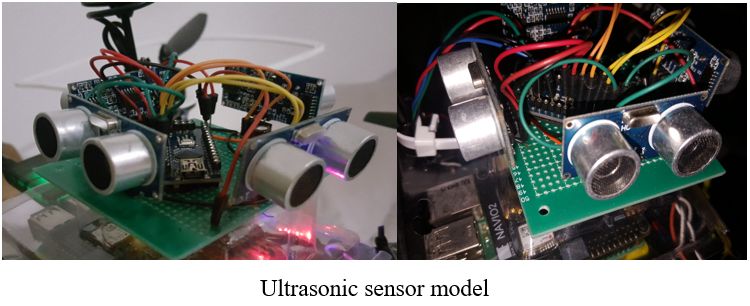
Connection points required were being precisely and tightly soldered on a copper board. Jumpers were used to ease out connections and female header pins were soldered on place for the installation of ultrasonic sensors in each direction, as shown below. capacitors and resistors were added to improve consistency of each sensor.

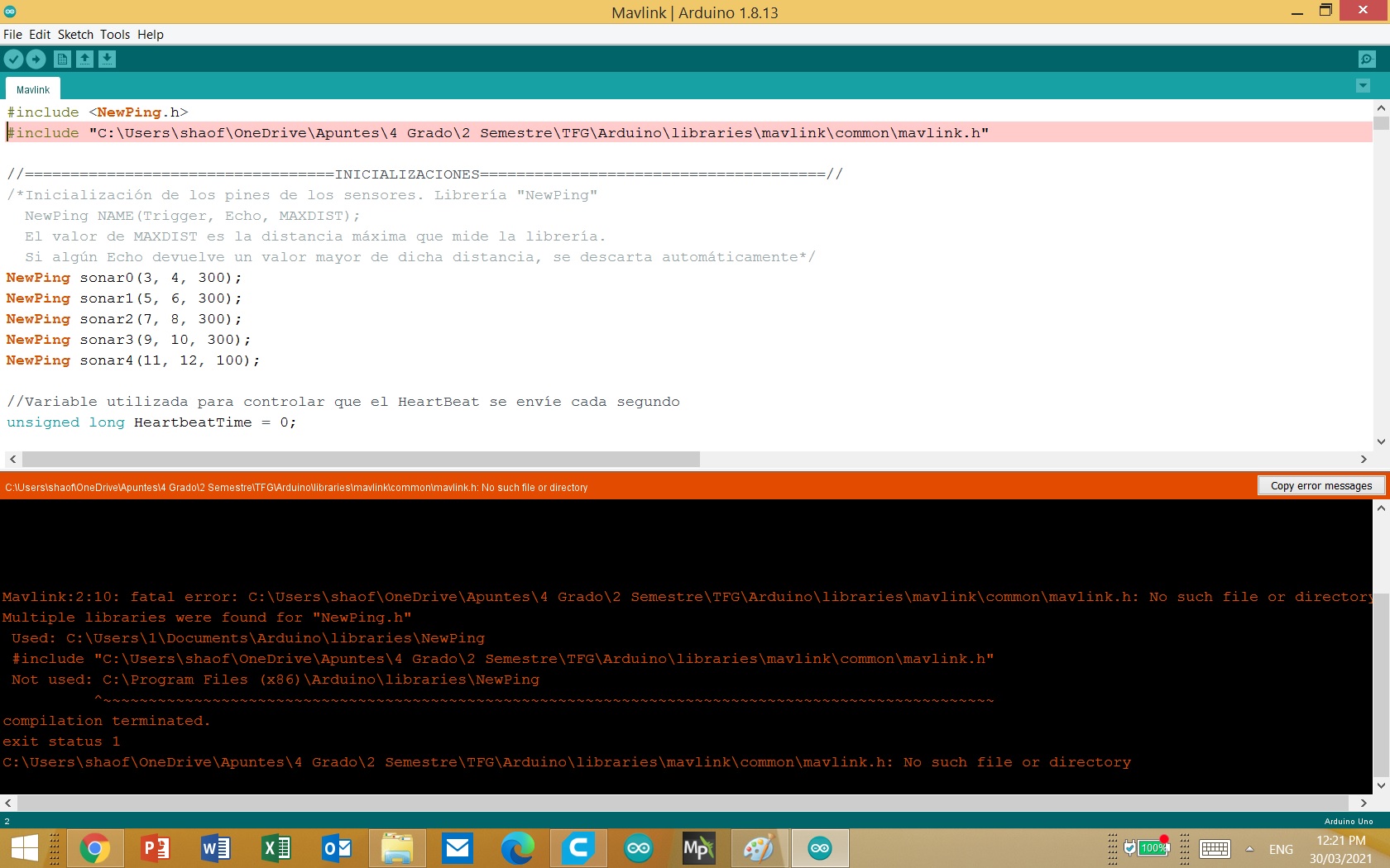
The software of the object avoidance system was built with the Arduino Software (IDE). For distance measurement, NewPing library was used to retrieve raw sensor data directly in centimetre. To improve overall sensor data consistency, averaged value of 5 sensor readings were taken. It was learnt that sonar outputting zero distance is not uncommon. It happens when the distance of the object is out of the detection range, or when there is a directional uncertainty. To avoid the average values getting affected by such errors, only average values with at least 4 non-zero readings are taken, otherwise discarded.
Pitch and roll responses can be realised by sending mavlink pakages containing signals to override the existing roll and pitch value. From the data flash logs, the input RC channel shows a value nearing 1500 for both pitch and roll values when the quadcopter is stable. When the quadcopter pitches nose down, the value drops below 1500, whereas when pitched up, the value rises above 1500 in the pitch channel. Likewise, when the quadcopter tilts to the right, it rises above 1500, in the roll channel, and vice versa.
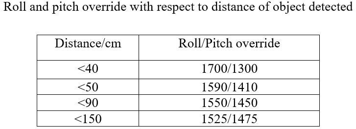
This piece of information is vital because the Mavlink messages that were sent from the Arduino microcontroller to the FC will be the messages to override those values in the respective radio channels. The Arduino software was coded in a way that the change in roll-pitch values increase when the nearest distance detected reduces.