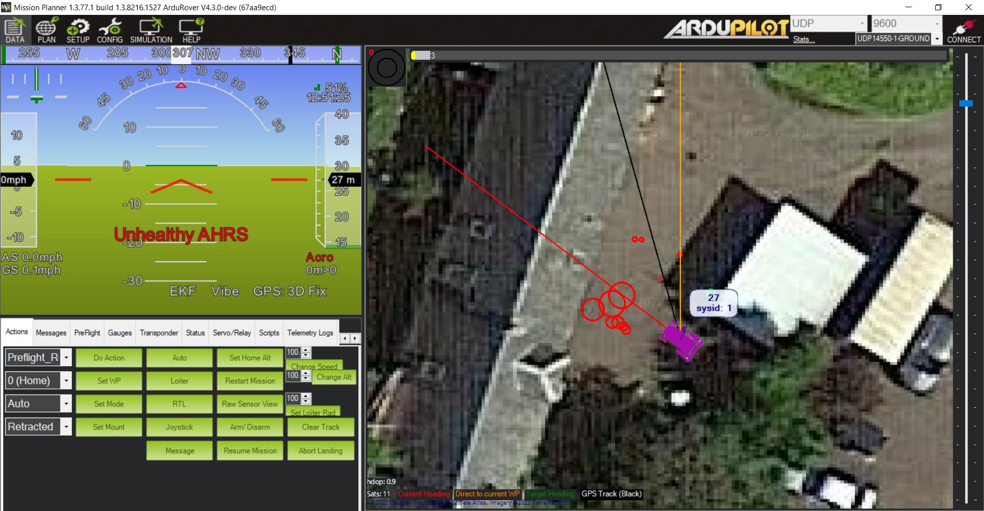
I come back with yet another question regarding my Rover, Now i have a problem with my 4 Rangefinders I bought for it (HC-SR04), so when there is an inaccuracy in the GPS location, It can avoid obstacles like curbs etc.
after plugging them in and configuring them indoors, everything seemed to work fine. I turned on Proximity Viewer on Misson Planner and it was showing correct values. Ardupilot site told me, that the range is 20-200 cm, but I saw that it can even go as low as 2cm, and as high as 400cm, which should me more than enough for me. It also said that these sensors are preffered for indoor use, BUT were succesfully used outdoors.
So i took it outside for testing, but i noticed something weird. After moving around 1 meter away from the closest obstacle, sensor stopped detecting this obstacle, and started showing some non-existent obstacle 80 cm away from the rover. So there are 2 weird things happening: Sensor stopping detecting after around 1 meter (which could be understandable because its being used outdoors, so the range could be shorter, but i didnt thought it would be that short), and after being more than 1 meter away form the obstacle, the sensor starts to detect some oobstacle that dosen’t exist, around 80cm away from it. (same thing happens on every 4 of them)
Also One more thing, i am using The SpeedyBeeF405 Wing Flight Controller, which only has 1mb of memory, so i am using the “lite” version of ardupilot, which doesn’t have some options for setting up Simple object avoidance, which i would like to use. I heard that i can customize the software to add the settings that i want to use, and remove others that I don’t need, but i didn’t do that yet. Could that be the issue?
Now i am wondering, is this issue software or hardware related? Maybe the sensors shouldn’t be used outdoors? (then why does the ArduPilot site say this sensor were succesfully used outdoors?)
you will need to make a custom firmware here to get the features you want.
The sr04 does work but its got a very wide beam so it tends to pick up everything, I tried to use one, but it was picking up flaws on the road or uneven grass and went nowhere thinking they were obstructions. that is not an issue on smooth indoor floors. I replaced them with VL53l1X lidars.
Could I tilt the sensors even more upwards so it won’t detect ground?
and one more question: I would consider buying the VL53l1X lidars if my sensors won’t work, but is there a possibility to conect it via GPIO pins rather than via I2C? I see that my FC has only 2 I2C ports, one of which I have already used for external compass, while i would be happy to have 4 sensors for front right, front left, left and right side of my vehicle. 1 wouldn’t be enough.
Aiming them up will help reduce the noise but it also reduces the range.
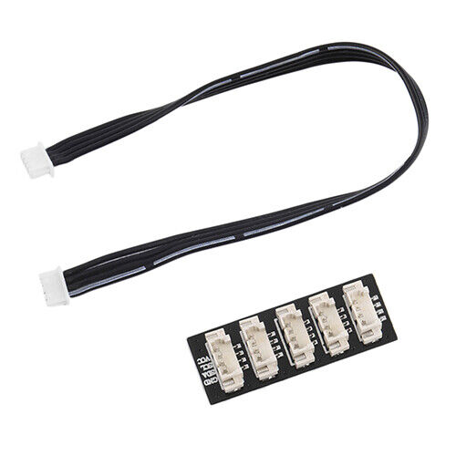
i2c is a bus, you can connect lots of devices as long as they have unique addresses just get a pixawk i2c bus splitter
To connect multiple VL53l1x lidars you will need to use an arduino to change their addresses on startup as they dont have any memory so they need set each boot.
If it won’t work, I will use the lidars, but I don’t really know how to wire the arduino to flight controller and sensors itself. Where the connections should be made? Thanks
The Arduino plugs into the i2c splitter along with the lidars using pins A4 and A5 for SCL and SDA, along with VCC and Ground then you run a single wire from A0 A1 A2 A3 pins on the Arduino to each lidars XSHUT pin.
Essentially what its doing is using the xshut pin to turn off the lidars so it can turn each one on then set its address before the flight controller starts up so they can all be detected.
#include <Wire.h>
#include <VL53L1X.h>

//#define XSHUT_pin6 A7  //not required for address change
//#define XSHUT_pin5 A6
#define XSHUT_pin4 A3
#define XSHUT_pin3 A2
#define XSHUT_pin2 A1
#define XSHUT_pin1 A0

//ADDRESS_DEFAULT 0b0101001 or 41
//#define Sensor1_newAddress 41 not required address change
#define Sensor2_newAddress 42
#define Sensor3_newAddress 43
#define Sensor4_newAddress 44
#define Sensor5_newAddress 45
#define Sensor6_newAddress 46

VL53L1X Sensor1;
VL53L1X Sensor2;
VL53L1X Sensor3;
VL53L1X Sensor4;
//VL53L1X Sensor5;
//VL53L1X Sensor6;

void setup()
{ /*WARNING*/
  //Shutdown pins of VL53L0X ACTIVE-LOW-ONLY NO TOLERANT TO 5V will fry them
  pinMode(XSHUT_pin1, OUTPUT);
  pinMode(XSHUT_pin2, OUTPUT);
  pinMode(XSHUT_pin3, OUTPUT);
  pinMode(XSHUT_pin4, OUTPUT);
//  pinMode(XSHUT_pin5, OUTPUT);
//  pinMode(XSHUT_pin6, OUTPUT);

  Serial.begin(115200);

  Wire.begin();
  //Change address of sensor and power up next one
 // Sensor6.setAddress(Sensor6_newAddress);//For power-up procedure t-boot max 1.2ms "Datasheet: 2.9 Power sequence"

 // pinMode(XSHUT_pin5, INPUT);
 // delay(10);
 // Sensor5.setAddress(Sensor5_newAddress);

  pinMode(XSHUT_pin4, INPUT);
  delay(10);
  Sensor4.setAddress(Sensor4_newAddress);

  pinMode(XSHUT_pin3, INPUT);
  delay(10);
  Sensor3.setAddress(Sensor3_newAddress);

  pinMode(XSHUT_pin2, INPUT);
  delay(10);
  Sensor2.setAddress(Sensor2_newAddress);

  pinMode(XSHUT_pin1, INPUT);
  delay(10);
  //ADDRESS_DEFAULT 0b0101001 or 41


}

void loop()
{


}
no the arduino does not go between them, everything is powered from the flight controller, the Arduino is taking control of the sensors, changing the address and then letting the flight controller take control of them. The reason this works is that ardupilot takes much longer to startup than this little program so it can change them before ardupilot looks for them.
you connect the splitter into your flight controller, that provides, 5v SCL SDA and GROUND signals
the lidars and the arduino all plug into the splitter, each getting a 5v, SCL SDA and ground
you add 1 extra wire between the arduino A0 A1 A2 A3 pins and each lidar.
you can buy the connectors prewired, the are jst 1.25 4pin.
I bought 2 vl53l0x, and 2 vl53l1x lidars (and the rest of things:arduino and splitter)
After wiring everything up, plugging it into the flight controller (to I2C port that was initially desingned for airspeed sensor), and turning it on, the board is stuck on boot loop, and won’t turn on, what could possibly be wrong? I checked the wiring but everything seemed ok.
Also, before wiring everything together, i plugged in a single sensor straight to I2C port, and everything worked fine.
you need the arduino board to change their addresses. They all have the same i2c address so conflict with each other, The Arduino board starts them one at a time and changes their addresses before the flight controller starts so they can all be detected with different addresses.
if your looking for a cheap 360 degree lidar i got one working here
I think i am having issues with the arduino and its code, maybe its because there are 2 different sensor models? Might need to add the library for the 0X sensor, but dont really know how…
With the help of AI i created the custom code, that should work with both types of sensors:
#include <Wire.h>
#include <VL53L1X.h>
#include <VL53L0X.h>

#define XSHUT_pin1 A0
#define XSHUT_pin2 A1
#define XSHUT_pin3 A2
#define XSHUT_pin4 A3

#define Sensor1_newAddress 41
#define Sensor2_newAddress 42
#define Sensor3_newAddress 43
#define Sensor4_newAddress 44

VL53L1X Sensor1;
VL53L1X Sensor2;
VL53L0X Sensor3;
VL53L0X Sensor4;

void setup()
{
  pinMode(XSHUT_pin1, OUTPUT);
  pinMode(XSHUT_pin2, OUTPUT);
  pinMode(XSHUT_pin3, OUTPUT);
  pinMode(XSHUT_pin4, OUTPUT);

  Serial.begin(9600);
  Serial.println("Serial communication started.");

  Wire.begin();

  pinMode(XSHUT_pin4, INPUT);
  delay(10);
  Sensor4.setAddress(Sensor4_newAddress); // Change this to the desired new address for VL53L0X
  Serial.println("VL53L0X Sensor 4 address change successful");

  pinMode(XSHUT_pin3, INPUT);
  delay(10);
  Sensor3.setAddress(Sensor3_newAddress); // Change this to the desired new address for VL53L0X
  Serial.println("VL53L0X Sensor 3 address change successful");

  pinMode(XSHUT_pin2, INPUT);
  delay(10);
  Sensor2.setAddress(Sensor2_newAddress);
  Serial.println("VL53L1X Sensor 2 address change successful");

  pinMode(XSHUT_pin1, INPUT);
  delay(10);
  Sensor1.setAddress(Sensor1_newAddress);
  Serial.println("VL53L1X Sensor 1 address change successful");

  Serial.println("Setup completed. Code will not loop anymore.");
}

void loop()
{
  // The loop function is empty, code will only run once.
}
But for some reason the code stops at: “Serial communication started” so it doesn’t change the addresses at all, any reason why? (as i said the wiring is as described, checked 3 times)
just try the code as i posted it , it will probably work for both.
Don’t post AI stuff, its never correct. no one has yet come in here with any information gave to them by an AI that was correct.
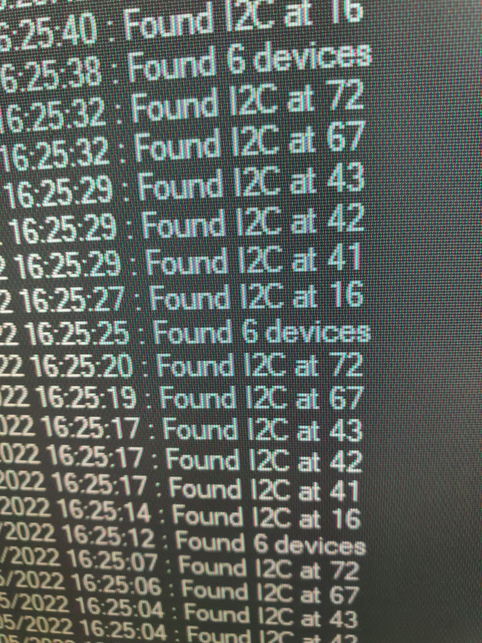
you need to download the i2c scanner script from the lua examples copy it to the scripting folder on the flight controller sd card then enable scripting
by the sounds of it you have the SCL and SDA mixed up on the arduino board.