olá, sou novo na comunidade, na qual é rica em informação.
mas a seguinte duvida é sobre, como eu poderia fazer waypoits sem a necessidade
de usar piloto automático, sem gps , apenas com plano de voo com base em processamento de
imagem. tendo como sensores câmera para auxiliar os movimento do meu rover. Por favor teria alguém com conhecimento especifico nessa área pra me ajudar, agradeço de coração
Não vale a pena tentar é demasiado complicado se não tens conhecimentos de processamento de imagem e visão.
Mas se tens e sabes o que é SLAM e odemetria visual, é simples. Basta gerares messages mavlink com coordenadas GPS criadas pela visão.
Existem muitos exemplos de odemetria visual neste fórum. Basta procurares.
1 Like
eu tinha essa duvida, pelo trabalho que seria, mas agora irei realmente focar no slam, faz bastante sentido. muito obrigadoo
Esse processo com SLAM, é um que é feito com ROS? Seria por esse caminho ??
Sim SLAM + mavros + ros2 humble é uma boa combinação
In case it helps, here is the list of supported methods of doing Non-GPS navigation.
For rovers, the simplest method is actually to use wheel encoders.
1 Like
There is a conflict between the orientation estimated by external devices like SLAM, and orientation provided by the compass! Could you please inform me of how to align them?
Hi @GarronLiu,
Misalignment of the yaw is one of the most common problems with using external vision systems. There are basically two solutions:
- If the external SLAM system provides yaw then don’t use the compass and instead rely on the SLAM system’s heading by setting the EK3_SRCx_YAW to 6 (ExternalNav)
- Use an RC switch to manually align the external SLAM system to the compass
- Check you are using the VISO_TYPE = 2 (T265) even if you’re using something else
- Set EKF to use compass for yaw. E.g SR3_SRC1_YAW = 1 (Compass)
- set RC7_OPTION = 80 (VisoAlign). See Auxiliary switch info here.
Method 2 is probably better and you should find that the external system’s yaw is aligned soon after it first starts providing position and heading. Then later on the pilot can re-align them by pulling the auxiliary switch high. Note that if you’re using a recent version of MP you can also trigger this alignment using the Aux Function tab (see below)

Thanks for your detailed guidance! I have tried these two solutions: the first solution works well without any warnings from MAVROS, which prints:
[ INFO] [1673680262.340298322]: FCU: EKFPosSource MIDDLE
[ INFO] [1673680262.341036118]: FCU: EKF3 IMU0 yaw aligned
[ INFO] [1673680262.343820174]: FCU: EKF3 IMU1 yaw aligned
[ INFO] [1673680262.381719728]: FCU: EKF3 IMU0 is using external nav data
[ INFO] [1673680262.382365944]: FCU: EKF3 IMU0 initial pos NED = -0.0,-0.0,-0.0 (m)
[ INFO] [1673680262.382776417]: FCU: EKF3 IMU1 is using external nav data
[ INFO] [1673680262.383434061]: FCU: EKF3 IMU1 initial pos NED = -0.0,-0.0,-0.0 (m)
[ INFO] [1673680262.386283343]: FCU: AHRS: EKF3 active
However, the second one was confronted with some warning from MAVROS( see below) even though the SLAM node is running normally.
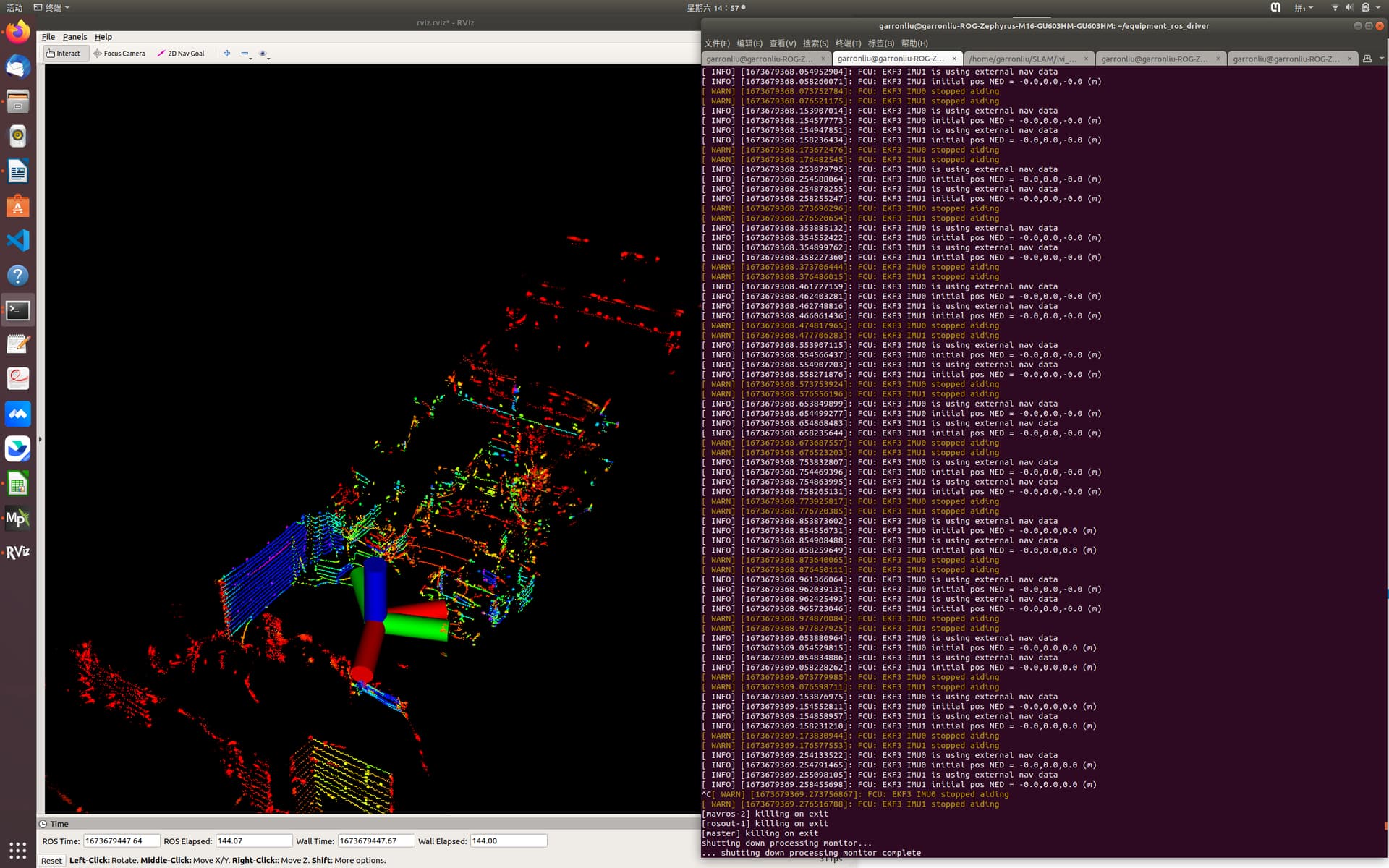
It seems that VisoAlign function does not take effects.
To help to diagnose the problem, the imu topic (left) used by the SLAM node and the imu topic (right) provided by the MAVROS are displayed below.
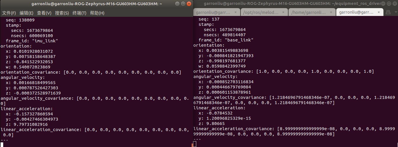
It can be found that the orientations between them are different.I wonder if I misunderstand the function of VisoAlign. If so, does it means that the SLAM need to provide MAVROS with the \robot_pose that is aligned with the orientation of the frame defined by Ardupilot?