Introduction
Hello AP community! I am Sanket Sharma, a fourth-year undergraduate student currently pursuing B.E. Mechatronics from India. I am happy to announce that I have been selected to work with Ardupilot again under GSoC’24 with my mentors @rmackay9 and @tridge. In this blog, I’ll be discussing my GSoC project focused on High Altitude Non-GPS Navigation.
This project aims to develop a high-altitude non-GPS position estimation algorithm for UAVs, enabling them to localize and navigate in GPS-denied areas at altitudes of at least 100m using a downward-facing camera. The project involves extensive work with computer vision, image processing, and advanced control systems to achieve precise location estimation without GPS.
Current Scenario
Ardupilot is an open-source and versatile autopilot system that provides support for several vehicle types (rovers, copters, planes, and more), sensors, and frame types. It has multiple autonomous features like RTL, Loiter, Auto, Guided mode, etc., all of which depend on GPS as the primary source of position estimate. While there are non-GPS navigation techniques available, they are mostly limited to low altitudes and indoor environments.
High-altitude pose estimation in GPS-denied environments can be a game-changer in the UAV industry, allowing drones to remain stable and reliable even after GPS loss at high altitudes. This feature will not only improve user experience but also enhance safety for people and the drones themselves.
Terms
Definitions of the important terms:
- SIFT (Scale-Invariant Feature Transform): An algorithm for detecting and describing local features in images.
- FLANN (Fast Library for Approximate Nearest Neighbors): Used for matching SIFT descriptors between different images.
- RANSAC (Random Sample Consensus): A method for robustly estimating a homography matrix by considering inlier matches and ignoring outliers.
- Homography: A transformation matrix used to align features in different images, accounting for rotation, translation, and changes in perspective.
- DSMAC: Digital Scene-Matching Area Correlator is a navigation technology that enhances accuracy by comparing real-time images with pre-stored terrain data. It enables precise location determination by matching current visuals to known reference scenes.
Approach
Though I have two approaches for the task:
- To have a map prior to the start of flight as a reference in case on GPS-Denied flights and use SIFT-FLAN (or AKAZE-FLANN) based image feature matching algorithm.
- Instead of having a map beforehand, we can calculate position based on an image matching and IMU back propagation based SLAM algorithm to estimate position of the UAV.
For GSOC, I have planned to go with the first approach to lay the foundation for developing the second approach.
I have divided the approach into 2 step tasks:
Step 1: Setting up SITL Simulation Environment and Adding the High Altitude Pose Estimation Feature
This task revolves around setting up the environment, dependencies, and configuring Ardupilot’s build system along with setting up a copter (software testing (SITL)).
- Setting up Ubuntu 22.04 for AP SITL
- Setting up Ardupilot SITL and Gazebo:
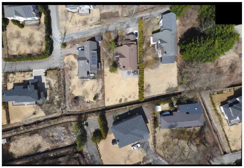
- Recreating the environment for high-altitude position estimation in Gazebo. I have added a sattelite TIFF scaled image to replicate high altitude environments.

- Setting up the required parameters as mentioned here.
- Modify Ardupilot’s codebase:
- A new parameter is planned to be added for this new feature/mode (e.g., NGPS_DATACOL for mapping purpose).
- Create an image stitching algorithm to create the map of the area. A SIFT based image stitching algorithm is made to stitch and form reference maps from the input images. Various image processing techniques like histogram equalization, etc, are used for seamless map stitching.

- Create the camera-based position estimation script using PyMAVLink and OpenCV. I have developed a SIFT-FLANN based position estimator using linear interpolation and extrapolation of known locations to map pixel coordinates to the actual locations. An AKAZE-FLANN based algorithm is also on checklist to compare with.

Another approach that we can use is basic trigonometry using camera’s intrinsic parameters.


- Test image stitching and localization in Gazebo simulation: Test done in Gazebo as mentioned above
Step 2: Setting up the Vehicle and Companion Computer Environment
Here we focus on setting up the vehicle and companion computer for making high-altitude non-GPS positioning a success.
- Setting up FCU for copter:
- Build the modified code and upload it to the FCU.
- Setting up the companion computer:
- Modify the PyMAVLink code for the companion computer and enable image capturing through the gimbal.
- Install all required packages on the companion computer.
- Parameters and Tuning the EKF:
- Set base parameters and fine-tune EKF and the position estimation script for visual odometry.
Some of my work and scripts associated are mentioned here.
Optional Task: Developing GPS/Non-GPS Transition Lua Script
If time allows, a LUA script will be developed to handle the transition between GPS and high-altitude non-GPS positioning.
Conclusion
This project aims to significantly improve the stability and reliability of UAVs in GPS-denied high-altitude environments, providing valuable capabilities to the Ardupilot community. I am looking forward to contributing to the Ardupilot codebase again under GSoC and working with the community.
I would love to hear your feedback and suggestions in the comments below. Thank you!
Associated PR’s and repositories: