
Hey, I am Shiv Tyagi. An undergraduate student from Delhi, India. I am extremely delighted to share that I have been selected as a contributor in GSoC, 2022 for ArduPilot with @rmackay9 and @peterbarker as my mentors. This blog is about discussing about my GSoC project.
My proposal was about adding a feature - AutoDocking in ArduRover. This would be a great feature to have on rovers. With this, we would be able to automatically park a rover at a docking station. This would reduce the efforts of the pilot to manually drive and park the vehicle at the desired location.
I propose to implement this feature with the help of a camera sensor attached to a companion computer which would help us track the dock and transmit relevant mavlink messages to the vehicle. These mavlink messages will be used at the vehicle end to estimate the precise position of the docking target and maneuver the rover towards it. More details about the implementation are explained in the next section.
PROPOSED APPROACH
In this project, we want to dock our rover at a docking station. To achieve this we need to precisely know the location of our docking station. For this, we would place an ArucoMarker at the dock. This marker would be scanned by the camera and we would estimate the pose using OpenCV library.
We have many choices of sensors to track the docking station. These include a camera with a companion computer, an IR lock, an AI camera, etc. A few reasons for choosing a camera with a companion computer for (tracking Aruco marker) in this project are:-
- It is cheaper than other options.
- For an IR lock, we would need an extra sensor (a rangefinder) to estimate the distance to the target.
- This would help us to uniquely identify a dock in case of multiple vehicles such that each vehicle is assigned a unique dock.
- If we use an IR Lock, Infrared rays from the sun might interfere with the sensor.
The current RTL (Return to Launch) mode in ArduPilot navigates the rover to the location where it was last armed. However, the direction in which the rover heads towards the return location is always the vector from the current location to the return location on the 2D plane on which the rover is moving (see figure 1).

Hence, there can be cases when our rover heads towards the return location such that the marker placed at the dock is never in sight of the camera (one such example is shown in figure 2) while returning home.
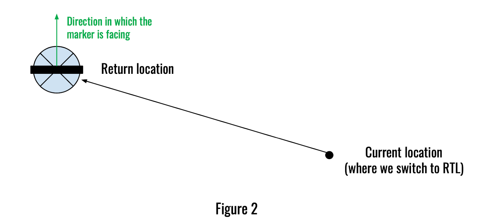
So, we need to make sure that the rover heads to the return location such that the maker we place at the dock is always in the sight of the camera on the rover. We will discuss the solution to this incorrect approach problem next.
A solution to the incorrect approach problem
I propose to solve this problem by adding an intermediate point on the vehicle’s journey back home. We will add a few parameters which would help us to determine the location of the intermediate point with respect to the final return position.
These parameters would be (we can decide on final names later),
- DOCK_IP_DIST: Distance (in m) of the intermediate point from the final return location,
- DOCK_IP_DIR: Direction (in degrees) of intermediate point as seen from return location
Hence, the location of the intermediate point will be calculated such that it is DOCK_IP_DIST meters away from the marker in DOCK_IP_DIR direction. This would make sure that the marker is in sight of the camera when we return back home.
We would modify the current RTL mode to have a submode (like those in Auto and Guided modes) named ‘Dock’ mode. This submode can be enabled using another parameter, say DOCK_ENABLE which when set to 1, would make the rover go to the return location via the intermediate point we just defined. Figure 3 shows an example flight path when we have this submode enabled.

As shown in the above figure, the journey would be split into two phases. In the first phase, the rover would be in the ‘moving to intermediate point’ state and in the second phase, it would be in the ‘docking’ state.
Docking Phase
It is the most important part of this project. In this phase, we will be sending LANDING_TARGET mavlink messages from the companion computer to the vehicle. This message will contain information about the position of the docking station with respect to the vehicle. To get this information we would use the OpenCV aruco marker detection library which helps us to estimate the pose of the marker placed at the docking station. This information will be fed in LANDING_TARGET messages sent to the vehicle. These messages will be consumed in a similar way to how it is done in the PrecLand library.
How would we test things?
I have planned to do most of my work on simulators. I would mostly be using SITL during the development period. We have really good code in SIM_Preland which can be reused (with minor changes) to simulate a marker at a docking station.
Having this would also help us to write autotests for the feature to make sure it doesn’t break in the future. In later stages, we will move to real vehicles for testing.
Setting orientation of the sensor in SIM_Precland
In SIM_Precland, we do not get an option to set the orientation of the simulated sensor. We currently have three types of sensors. These are spherical, conical, and cylindrical.
- Spherical: The spherical type can be used for our task initially as it emits beams in all directions around it. Hence, once our rover reaches inside the radius of the sphere, we would start getting data from the simulated sensor.
- Conical: Initially we can do our tests on spherical beacons but to do more realistic testing, having a sensor emitting beams conically would be great. Currently, the conical type of sensor has PITCH_90 orientation (it emits beams conically towards the sky) as shown in figure 4 below.
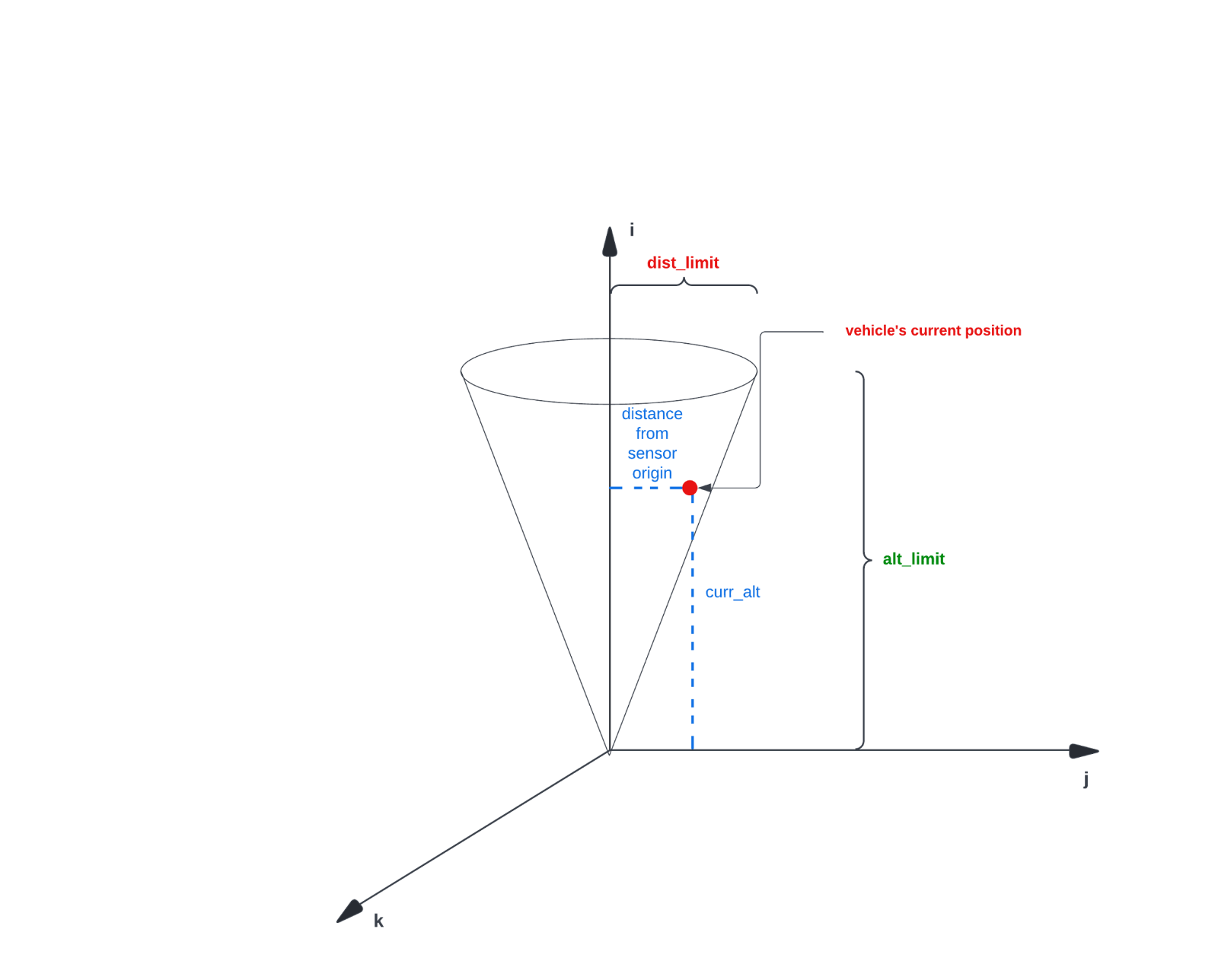
Figure 4
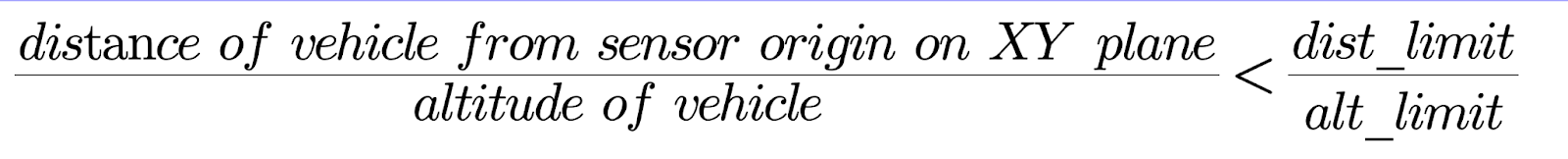
The sensor returns a healthy state if the position of our vehicle is inside this virtual cone. Dist_limit and alt_limit are the radius and height of the cone respectively. If the distance from the vehicle to the sensor origin on the XY plane and the altitude of the vehicle satisfies the equation written below, we say that the vehicle is inside the cone.
But for the cone which is not in the orientation shown above, the mathematics has to be different. We need to derive an equation that checks if the vehicle is inside the cone for any possible orientation of the cone. Let us take the example of the cone shown in figure 5.
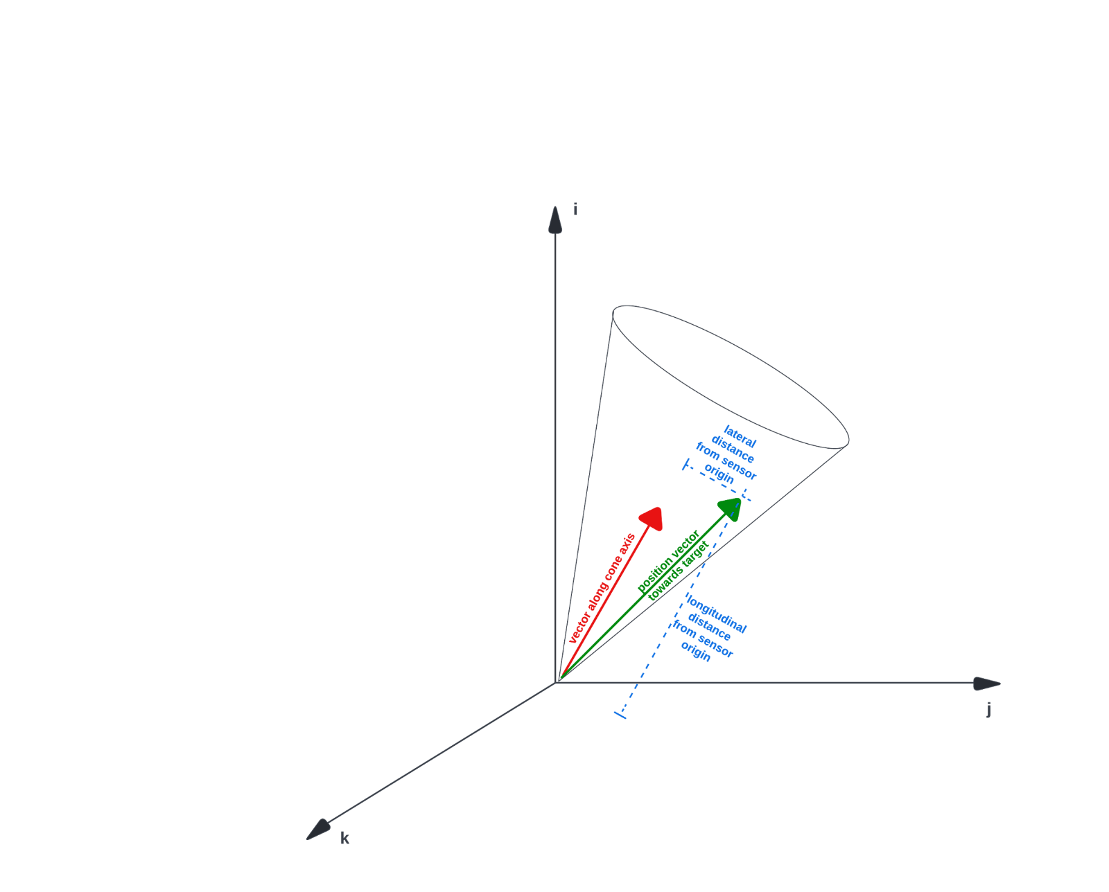
Figure 5
Let a be the 3D position vector of the vehicle and b be a unit vector along the axis of the cone. The vector b can be easily constructed given the orientation of the beacon in terms of roll, pitch, and yaw.
Let long_dist be the longitudinal distance from the vehicle to beacon and lat_dist be the lateral distance from the vehicle to beacon.
Clearly, long_dist = projection of a on b
i.e.,
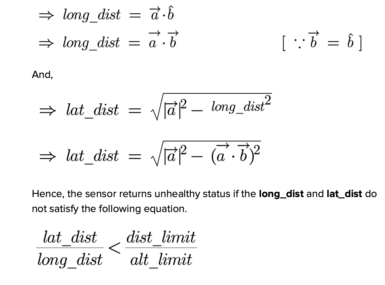
The above equation can be applied to any vehicle for any possible orientation of the cone.
- Cylindrical: We can redo similar mathematics we did in the case of the conical beacon for the cylindrical beacon too.
Instead of asking the user to set the roll, pitch, and yaw of the beacon separately, we would add another parameter named SIM_PLD_ORIENT in SIM_Precland which would accept values like ‘0:Forward, 1:Forward-Right, 2:Right, 3:Back-Right, 4:Back, 5:Back-Left, 6:Left, 7:Forward-Left, 24:Up, 25:Down’ as we do to set the orientation of rangefinders.
It would be really great to know how the community and dev team members think about this approach. The suggestions and comments are always welcome and we can discuss the same below in comments.
Thanks!