
It is the year 2018.
Ardupilot forces have victoriously swept over most of the RC world. Both enthusiast and academic communities alike, have been taken over by this brand of elite and deadly-reliable autopilot software. Current reports from the ground indicate that their arsenal includes sophisticated Multicopters, Helicopters, Planes, (a HUGE list) and now more recently… what’s that? BALANCE BOTS too!
The serious stuff begins…
The concept of a Self Balancing Robot(Balance Bot) running on Ardupilot software, though still a very refreshing idea, is not entirely new. It was done way back by Jason Short, one of the first ArduCopter developers. More recently, Jonathan Challinger also made his Balance Bot based on Ardupilot. The robust and modular software structure, extensive hardware support and easy to implement libraries, makes Ardupilot an ideal platform for a Balance Bot. The aim of this project is to build on this idea and turn the Balance Bot into a fully supported Ardupilot platform, as an extension to the Rover vehicle class.
How it works
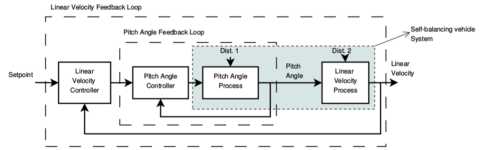
We use a two stage control algorithm for the balance bot. The first order of business here, is to ensure the balance bot does not topple. The inner loop of the controller uses the IMU sensors to get the present pitch(lean) angle which it compares with a desired pitch angle, to send an appropriate throttle value to the motors. This desired pitch angle is zero(upright) when the bot is not moving. What happens when it wants to move? In that case, the desired pitch will be set to a small angle in the direction of movement. If the bot tries maintain a forward pitch, it will have to accelerate forward to keep its balance and likewise for reverse. The outer control loop controls linear velocity. It basically sees to it that the acceleration due to pitching in any direction does not go out of hand by modifying the desired pitch accordingly. Balance bots by design use a differential drive or skid steering. So turning is done by setting different velocities to each wheel.
Phase one: Simulation
Simulation for Ardupilot, is more than just a convenience tool for testing and development. The SITL simulator forms the bedrock for Ardupilot’s continuous integration checks. Those are tests, that each patch to the main code has to clear before it is accepted. This ensures that no patch can corrupt or break the functioning of the existing code, while keeping code contribution simple and open to all. So basically, no new vehicle code can be acceptable without an SITL simulator backing it.
The fact that SITL is one of those libraries without any examples or documentation, makes it a demon to wrestle, for newbies to the code base. I intend to change that after this project. Still, after a week or two of frustration, dead ends, lots of studying physics  and because of my two amazing mentors, we managed to get a reasonably good simulator running, It still needs a bit more work to make it accurate. These are the sources I used to model the balance bot:
http://ctms.engin.umich.edu/CTMS/index.php?example=InvertedPendulum§ion=SystemModeling
http://journals.sagepub.com/doi/pdf/10.5772/63933
Phase two: Testing on the real robot
Here is a video of one my first tests:
Evidently, it was very unstable. Even after some painstaking PID tuning, it still wouldn’t stabilise properly. One reason as I later figured out(when Jonathan Challinger told me), was that all the weight was at the bottom. This means very low centre of gravity and hence low inertia, making it incredibly difficult to balance. Remember trying to balance a stick with a lump of clay on it? Same thing really. This could be fixed by moving the battery to the top. The second reason was that the adaptor between the motors and wheels had a considerable amount of backlash, which is OK for a rover but unforgivable for a balance bot. That meant getting new wheels.
Phase three: Manual Mode(Current)
Manual mode in rover, means the user inputs are directly mapped to the motors without any control system in between. For the balance bot, we decided to implement only the inner loop for pitch control, in Manual mode. The speed control would be up to the user. One downside would be that it is incredibly hard to move the robot without toppling it, because constant pitching can easily make it accelerate out of control. But again, manual mode is for the experts  (which I definitely am not)
In this trial, I moved the battery to the top, but the wheels are still the same. So the robot is a bit twitchy when it moves. Take a look:
What’s next?
The short version: there’s more left to be done than what’s done. The immediate tasks in front would be:
- Improve the accuracy of the SITL model
- Add the second control loop for speed control(using wheel encoders for feedback)
- Test and verify each rover mode
- User Documentation
- Unit Tests
Parts used
- Pixfalcon (switching to Pixhawk clone, to use wheel enoders and DIR/PWM motor driver)
- SiK Telemetry radio
- Quicrun 1060 brushed ESC (Switching to DIR/PWM motor driver)
- Flysky FS-i6s RX/TX
- 200RPM 12V motors (Switching to 600rpm motors with encoder)
- 3000mAh Lipo battery
- Ublox M8N GPS(currently disabled for testing indoors )
On a closing note, I’d like to add that the real brains behind the operation have been my mentors @tridge and @peterbarker. Without these guys, I really would have been lost at sea(probably still figuring out the SITL stuff  ). Special mention to @rmackay9 and @jschall for all the help and advice.
