@rmackay9 and @tridge
Having several users report that the hall effects sensor that comes with the futaba GV-1/701 governors does not work in Copter 4.0. The Futaba governor itself is not being used just the sensor used to measure RPM that comes with the governor is being used with the flight controller to measure rotor RPM. Discussion in this thread. The discussion continues in the thread and @jinchengde conducted a test where the software was reverted back to 3.6.12 and the sensor worked. Then loading 4.0.5, it caused an error. The firmware has the following error INTERNAL ERROR 0X2000000. From looking at the code, the error code refers to the GPIO ISR.
Hopefully one of you can shed some light on this issue and tell us how to fix it because I’m not sure if it is a hardware or software thing.
Thanks,
Bill
@bnsgeyer
so is that cause the ISR Flood Issue?
I have also been bitten by this bug, but with an aerospire sensor. I wrote some new governor code for Copter 4.1, but when I went to test it, I get no rpm signal at all (testing on Copter 4.0.5). Reverting the firmware to Copter 3.6.12, the same sensor works fine.
I am using a Drotek Pixhawk3 Pro, not sure what controllers others are having problems with. But it doesn’t appear that the issue is limited to the Futaba sensor.
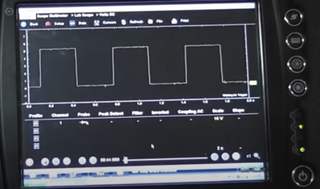
@jinchengde I just happened to stumble upon the same issue, hopefully tridge an take a look and tell us what to do to figure it out. It doesn’t appear to be sensor-specific, I did send a photo to tridge of what the signal looks like on my sensor. It could be controller-specific since some people report it works, others appear to be having problems with it. If others have a lab scope maybe post a photo of what the signal looks like for comparison. I think one suspect was noise on the signal causing the number of samples to go over 10K/100ms, at which point the the signal would be rejected due to too many interrupts causing the cpu to run out of time to do other stuff.
if (dt > 100 && dt < 1000*1000) {
    irq_state[state.instance].dt_sum += dt;
    irq_state[state.instance].dt_count++;
}

Normally I can get a rpm reading just by turning the rotor by hand as long as it’s going at least 60 rpm. I think I have my min and max set to 60 and 2500. This is difficult to do with engine running because even a small amount of throttle causes the rotor head to severely over-speed with no blades on it. With blades, can’t get close enough to the helicopter to mess with a lab scope without getting something cut or chopping your hand or arm off. So I turned it by hand and had wife take a photo of the scope screen. My sensor puts out right on about 5V with air gap on magnets at ~2mm.
@ChrisOlson could you post log files and param files for each version of software. @tridge mentioned in the devcall that chibios is pickier about ports and pads. In 3.6, it wasn’t enforcing the interrupt requests and now they do in 4.0. So he could determine whether this is the issue from looking at the back to back logs and params between 3.6 and 4.0. Hopefully you are able to provide this information.
Any other users experiencing this issue (@jinchengde), if you can provide logs and params files, it would help getting to the bottom of this issue.
Thanks,
Bill
the nitro engine rpm is always go over 10k
@bnsgeyer sent direct to tridge via email instead of posting here.
@jinchengde while the 4.0 governor will kind of work measuring engine rpm, the new governor I am working on for 4.1 will only work measuring rotor speed. This is for heli only, does not apply to plane.
@bnsgeyer @ChrisOlson
I found if I move the magnet under the futaba gv-1 sensor and hold the position for 5 seconds, ardupilot will have “ISR Flood” issue and then interner error 0x2000000, so if I choose move the magnet away from sensor during bootup, and runup the engine, the sensor work well.
I suppose that maybe need some pulldown resistor for futaba gv-1 sensor.
@jinchengde I suggest you read this thread
And maybe @IAMMATT might be able to help with this question.
thanks bill, I will read it and find some clue
I have not used a GV-1/701 before, but yes there is good chance that you need a extra resistor. I have had to add pull up resistors on a number of different sensors now. If you you have a scope use that to test. Alternatively use an arduino to confirm that the sensor is working using the script I provided here.