hi, I built VTOL 4+1 today I made the first takeoff and there was a feeling that there was little traction, if the first time I took off by one and a half meters, the second time I couldn’t even get up, the battery with a high rating of 6200/6s 90 with a load does not actually sink. VMG T-MOTOR MN4014 KV400, prop 15/5.5. probably not enough traction, what can I say from this video? the drone has 2 Lipo 6200/6s batteries for takeoff, and the fifth motor has its own 12000/6s Lyon battery первый тест втол - YouTube
13-14 m/s is more adequate as ARSPD_FBW_MIN from my experience.
PS Rolf, could you share your params?
Thanks for the info Steve, 12-14 m/s fits better. Greg @GregCovey had once flown the stall speed for his lighter 6s with probably 8kg TOW to 10 m/s in level flight. Mathematically, this results in 11.2 m/s for 10 kg and 12 m/s for 11.5 kg. This applies to turbulence-free, undisturbed flight in calm air.
In turns this results at 30° bank with 10 kg (correspond to 11.6 kg) stallspeed at 12 m/s and at 45° bank (10 kg correspond to 14.1 kg), stall at 13.1 m/s
Sure, but they are not flown out in any way and no adjustments to FBWA_MIN/MAX etc or TECS values yet. I have as I said ONLY taken the default values from arduplane, once the calculation for 20 inch props of Missionplanner run over it and played a little on the P and D values. Under this the hovering was not so bad. But after a few seconds I landed again, because the power consumption was displayed so high. If you want to look at the parameters anyway:
LF.param (24.1 KB)
Fortunately, the power consumption has been clarified. I have calibrated correct today with a clamp ammeter and came to less than half of the previous BATT_AMP_PERVLT.
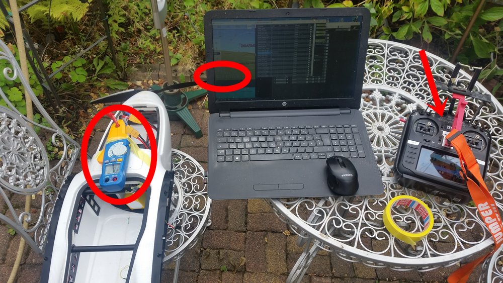
For setting I mounted a propeller, so that one could flow at least a few amps of current. On the missionplanner, the HUD display is separated, so that you can see the amperage display without changing the window and change BATT_AMP_PERVLT at the same time. On the transmitter, just for the test, the throttle is put on a knob.
Power consumption is therefore in the green range as with you others with 12s. This reassures me very much and next time I will be able to hover longer and adjust the parameters.
Cheers
Rolf
1 Like
Hey. What is the formula you use for this calculation?
The lift equation is
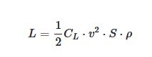
where S is wing area, CL coefficient of lift, ρ air density, and v airspeed. Using units of measure m2 for S, m/s for v, and kg/m3 for ρ, the result is lift in N (newtons).
Once you know the stall speed of an airplane of known weight, you can see from the formula that the lift is proportional to the square of the airspeed, since all other factors of the lift formula have not been changed (assuming the same configuration - flaps and center of gravity - of the aircraft).
The rest is rule of three .
3 Likes
Thank you for that! Ill try to learn more.
Were there issues in the calibration values given by Mauch for the Hall sensors? I have a clamp meter at work and have been curious to check the current values in MP so I know battery characteristics better.
-Christian
No, the problems were mine. I had lost the Mauch data sheet (or they were flooded here a year ago during the flood). I have therefore tried to set the first values with the “battery recharge method” - probably completely incorrect (The batteries are only little used and the new charger probably adds up the charged mAh even when balancing between the cells).
The accuracy of the calibration of the clamp ammeter intended for low DC voltages is specified by the manufacturer as about 3%, which is sufficient.
I went hovering over the weekend. Basically, QSTABILZE, QHOVER and QLOITER works fine, only with the PID values for the pitch axis I am not yet I am not yet satisfied. Either the tail vibrates visibly or the tail sways up. The latter is too risky for me, if it swings up so during the back transition. In the next few days I will try this again and maybe use the script from Tridge (ardupilot/libraries/AP_Scripting/applets/VTOL-quicktune.md at master · ArduPilot/ardupilot · GitHub) . I will report in any case.
1 Like
Update:
After completing repairs on the motor arm I remounted the hinges using epoxy and then attached 3D printed reinforcement parts with new rivets. I updated the 3D parts with a little bit of curvature and rounded some edges for aesthetics mostly. The flanges that cover the hinge can be attached with short M3 bolts if desired or cut off entirely. Within the flange, there is a thinner cross-section that covers the hinge screw in case one needs to access it in the future. I tested the epoxy on the carbon fiber tube and aluminum separately beforehand to be sure that it would bond well.
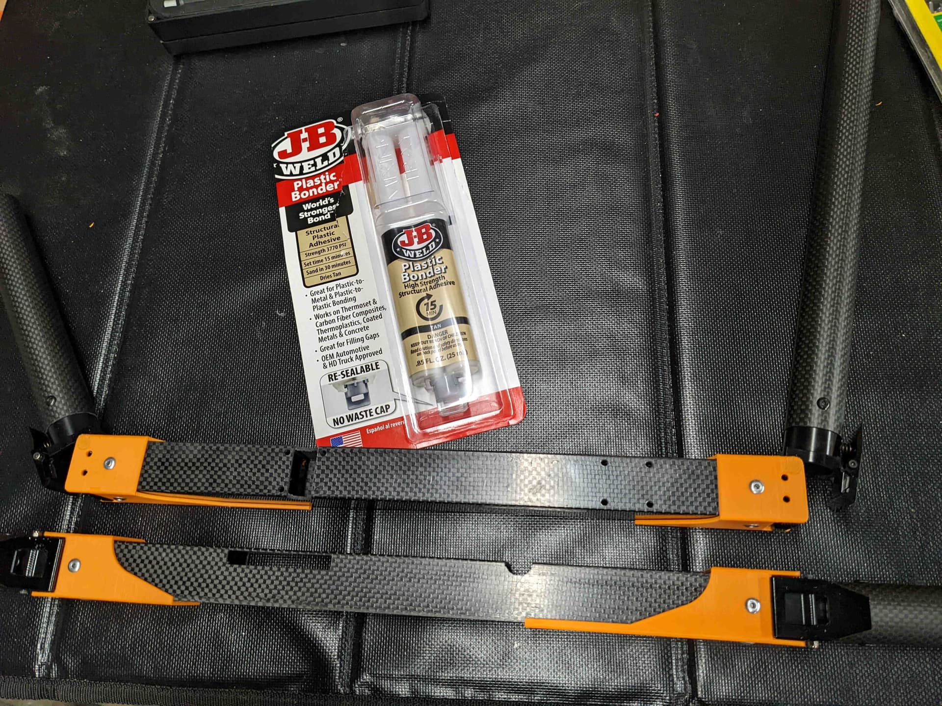
Photo 1: Motor arm reinforcement parts.
I re-glued a few of the plastic aileron hinges that had come loose including replacing one that was damaged. The damage to the foam was repaired using Gorilla white glue and packing tape since the glue expands to fill the gap. The damage was before the end of the carbon fiber spar so I glued/filled the foam first then decided that a reinforcement (wood skewer or carbon fiber spar) was not needed.

Photo 2: Motor arms mounted top view.
I had to trim a bit of foam to get the 3D printed pieces to sit in properly though it was minimal.
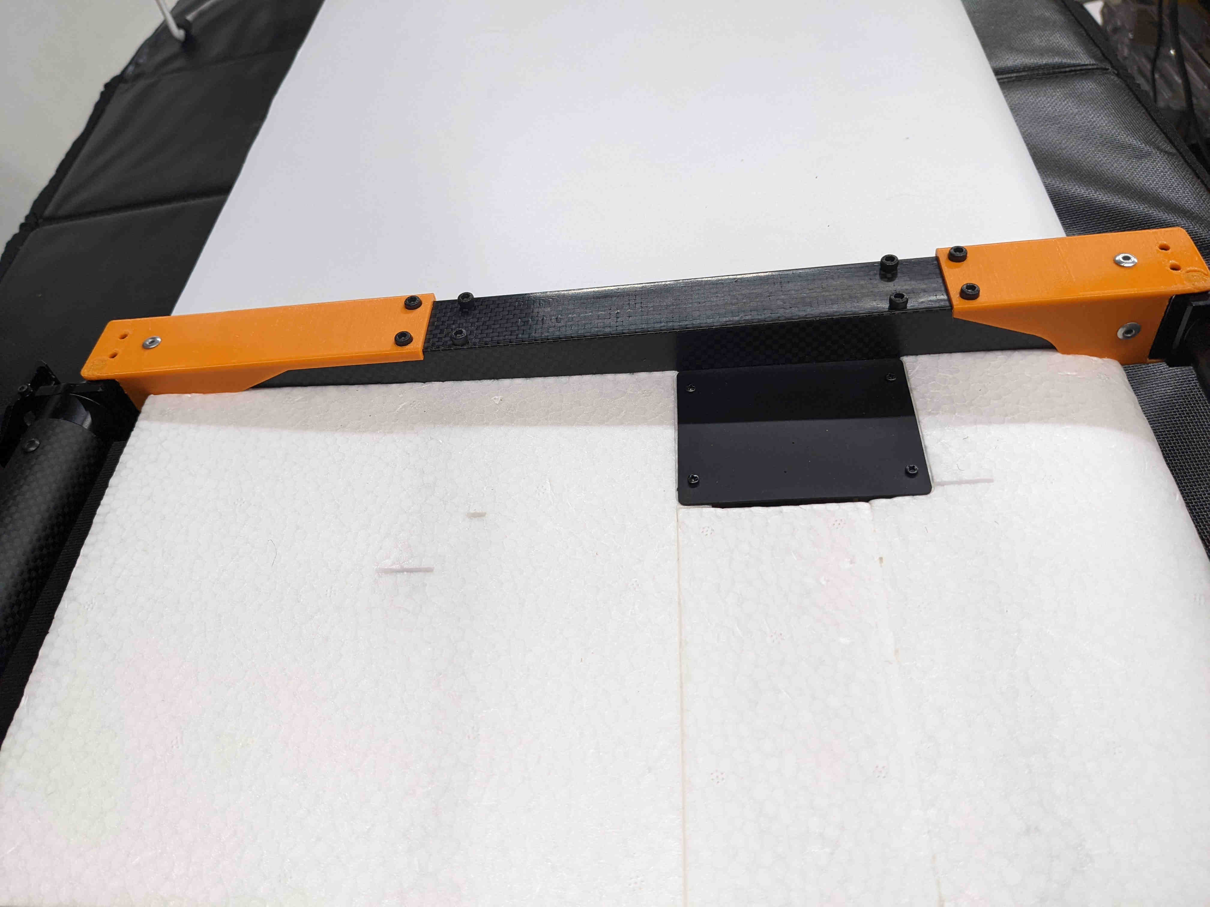
Photo 3: Motor arms mounted bottom view.
I did some test flight hovering after these repairs and everything behaved great. I did manage to toast the VTOL LiPos (hot/puffing) somehow so I ordered new ones of higher quality (Tattu). Once weather looks good here again I’ll be out doing more hover tests to work on PIDs and then notch filters if needed.
Cheers,
Christian
1 Like
Hi Christian, long time…our fighter has been on the shelf for a while as well…too busy with other projects, but once it gets cooler out and our sampling and bathymetry work is complete for the year we will dive back into this. Are you still planning on using the fighter as a platform for the magnetometer, or are you outfitting it with a multispectral sensor? Just curious as a longer duration mag survey kit is still very appealing. Best of luck.
Hey Ian,
Hope things have been going well for you!
I still plan to use the magnetometer sling on the Fighter. Currently it is set up for our multispectral camera which is easier to manage for the initial test flights, sort of a “step one” in the process. I am drawing up some removable landing gear posts so that the magnetometer cable has room to lay freely on the ground under the Fighter when launching/landing. I’ll share my logs/stats as I march along.
Cheers,
Christian
Hey everyone,
Has anyone found a pitot tube (store bought) that fits the Fighter’s wing (approx 6"/150mm)?
If I make my own using a 2mm or 3/32" tube, what size holes should I drill? Is it ok to have just one tube?
Thanks!
The common pitot tubes all fit when you push out the plastic tube. See my pictures there: Fighter VTOL 4+1 fixed wing - #575 by Rolf
I cannot say how good the single-tube solution is, where the static pressure is measured in the chamber for the sensor, because I take both pressures from the double-walled Pitot tube.
Rolf
1 Like
Thanks, Rolf!
One of the other things that caught me by surprise, is that the VTOL motor/ESC mounts weren’t tightened down onto their CF arms at the factory. Other than using a digital level, is there a trick to getting them all perfectly level?
A level was difficult to use for me. I instead used an aluminum straight edge (cutting guide for plywood sheets) laid across the top of the left and right motors with props on to check the angle of the motors. You can easily see if the props are parallel to the straight edge and can measure the difference if you want. I did this for the front set and then the rear set of motors. Having them level is the goal and in Arduplane docs it is suggested to have them tilted inward 5° for better yaw control if required for your VTOL. Just make sure none of the props/motors tilt outward.
Put some locktite on those screws too.
Cheers,
Christian
1 Like
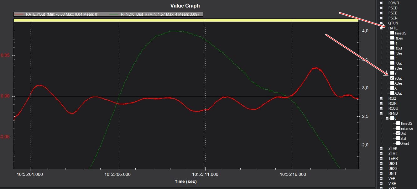
I did it similar to @Christian_H and used an aluminum L-profile. However you set it up, you can see the result when hovering (in still air) according to the wiki Tuning Process Instructions — Plane documentation in the logfile at the RATE YOut value, which should be below 0.1.
Cheers
Rolf
2 Likes
Thanks Christian and Rolf!
I have a digital level showing up tomorrow and an IBeam level a few days later.
I’m curious if anyone here used the 5° inward tilt for their Fighter? We’ll most often fly in the 6000-9000 foot MSL range. Often in windy conditions.
Thanks!
1 Like
someone has flutter problems, I’m having it.
Hi Rocio,
welcome to the forum and to the VTOL area.
A more detailed description (fluttering while hovering or in airplane mode ?) and especially a link to a logfile would be essential for help.
Rolf
Hello, I’m asking someone to give me a hand, I can’t find a way for the plane to keep my height and constant throttle in auto modes. I notice that it lowers height and raises the accelerator then raises and lowers it and so on all the time. I also notice that it is not stable in flight. In FBWA mode, this does not happen to me, once the little in my cruising speed that is 19m/s works fine.
Flight lod attached.
https://drive.google.com/drive/folders/1pfBiyVzaiOflpB2_rAFXBoWUrn7lIrQr?usp=sharing
Cheers
Alfredo