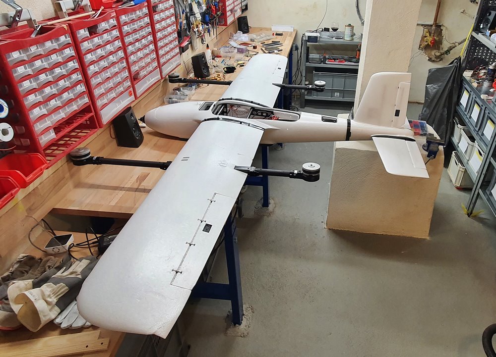
In the meantime, the fuselage , wings and electrical wiring are completed and the motors and ESCs are installed.
I got around the problem of the hard to separate SUB-D connectors at the tail by only screwing one side of the SUB-D connectors. When removing the tail, the connector with the cable is therefore pulled out of the fuselage a few centimeters so that you can easily separate the connector by hand.
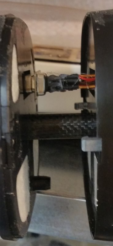
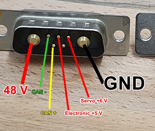
On the wings, loosening the large SUB D connector with the two high-current contacts is easier than expected, since you can pull on the brackets of the quad motors without running the risk of pressing the foam somewhere. I have only installed the front connectors, which could later be used to control all functions via CAN-BUS and a Matek L431 CAN NODE.
The power supply has a 3s safety battery that can power the electronics and servos independently of the main batteries. At the same time, this has the advantage that the electronics can be supplied with power for adjustment work without motors being under voltage.
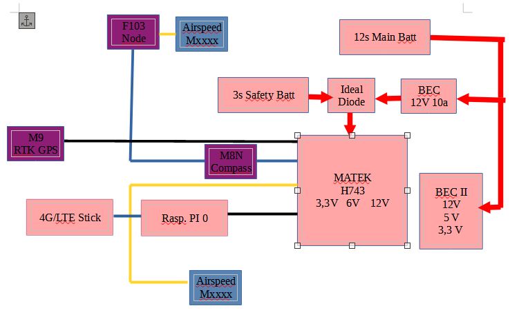
Another 12s to 3.3V / 5 V / 12 V BEC is used to power other electronics and the FPV system.
As flight controller I have planned a Matek H743-Wing(V1), which will be installed together with the BECs and the emergency battery on the “deck” for the flight controller. The disadvantage of the H743 is that it has only one CAN bus.
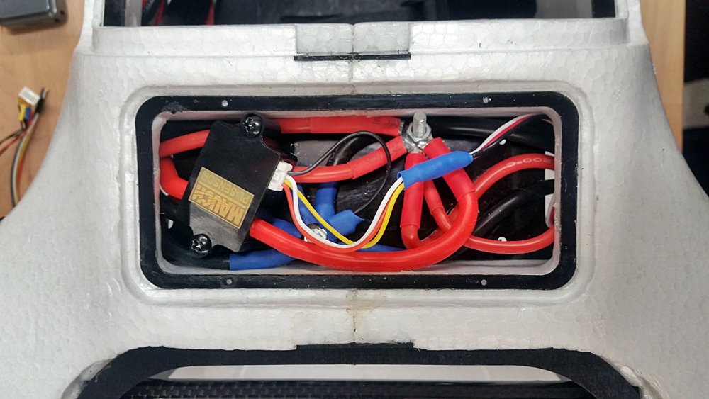
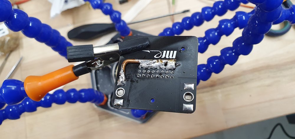
To avoid ground loops, a thick GND cable is routed in the fuselage (10 AWS). The connections of the cables to the wings and the front motor with the main battery via the Mauch sensor I have placed in the front transverse bay with screw connections.
To avoid ground loops I also soldered the GND connectors of the servo/ESC contacts with a thick copper wire to GND on the backside of the wing wiring boards.
The main batteries are connected on the positive side with a 7mm gold contact banana plug with anti-flash function. These plugs are more handy and in case of an emergency quicker and easier to disconnect than the XT90 plugs.

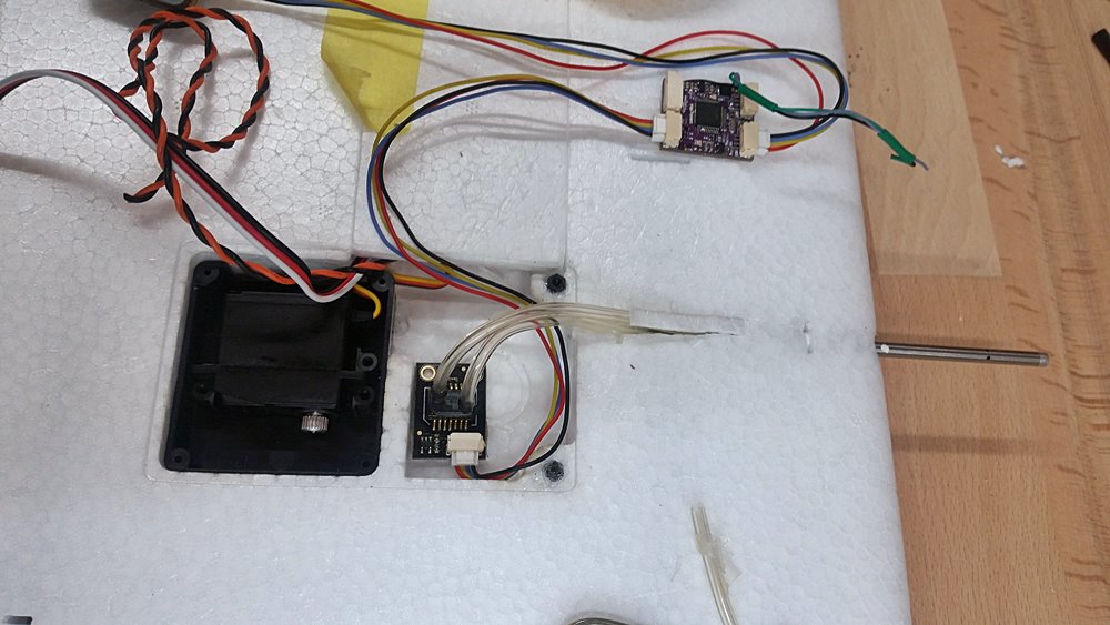
As Tridge mentioned ( Striver mini VTOL 4+1 QuadPlane - #200 by tridge ) I have taken the Pitot tubes further out and I also take the static pressure from the Pitot tube and not from the mounting chamber of the pressure sensor as shown in the MFE films. The plastic tube can be pushed forward very easily with a screwdriver and then removed. This makes room for a pitot tube. To let it extend further at the front, I used a cutter to open a small part of the “tunnel” at the top so that there was room for the bulge of the Pitot tube.


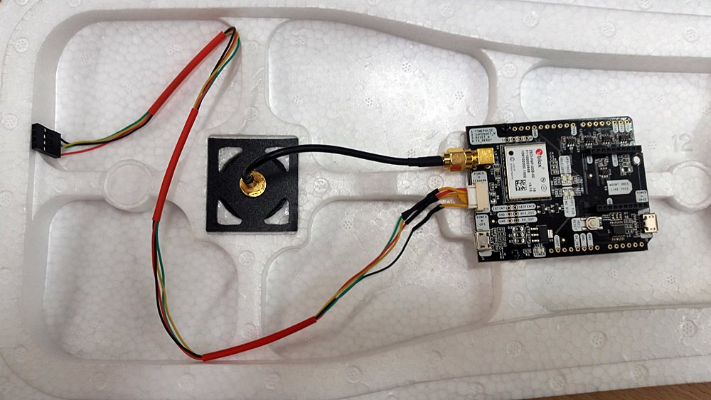
The UBOX F9P GPS is installed in the center of the aircraft, while an M8N GPS with compass is to be installed in the rear.

A Raspberry Pi 0 is responsible for the Mavlink telemetry via LTE connection as companion computer. The LTE stick is to be installed far forward. As software runs UAV Matrix https://uavmatrix.com/
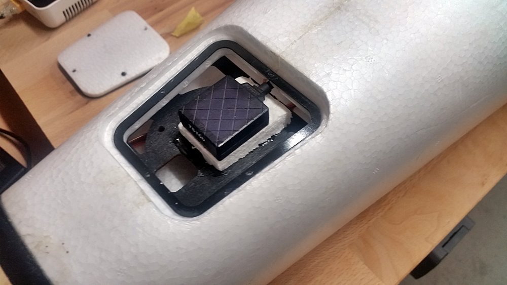
In the parachute bay I want to install a LIDAR, the TBS Crossfire Diversity Rx
and an ESP-01 for fast MAVLINK connection via WIFI on the ground.
At the first test weighing with two 6s 16000 mAh batteries connected to 12s in series, I arrive at about 9 kg takeoff weight.
there is still a lot of soldering to do, but I am already looking forward to the first flight.
Rolf