Hi Jed,
what are the average and peak currents while hovering ?
Hi Rolf
Average in about 45A peak 47 it’s fairly linear
Hi Jed - thanks for that info.
Hi Steven,
What are you planning to use with regards to batteries for your setup with your parallel 6S (multiple redundancy) system? Separate VTOL and Cruise motor batteries?
Cheers
Jeff
Hi Jed,
Just wondering if you have made a modification to your VTOL arm, folding mechanisms? Mine are quite different and mount internally into the square carbon fibre tube. Would you be able to post a few detail photos if you are OK with that? Interested to see what you’ve done and why?
and regarding the laminating film - there is a big range of weights/thicknesses within this type of film…do you happen to know what the micron number is for the film that you have been using - I’m interested to see how that compares with the film that I already have. I realise that this is a very basic question, but it’s always nice to have a comparison with what others (like yourself) who are successfully using materials to modify and enhance their aircraft.
Cheers
Jeff
Hi Jeff,
The dual battery redunancy was going to be the Mauch setup found here; 100A / 200A Hall Sensor PM for Pixhawk / APM - PC-2x15A Ideal D / BattShare
Postage for the fighter has put this project on hold - other redunancy was CAN ESC’s with KEDCAN ESC also able to run PWM (though I’m now uncertain if PWM is actually redundancy)
Steve
Hi Jeff
I strengthened the arms where the tube goes into the square carbon fiber as mine started to crack, I made some 1mm stainless sleeves and bonded them to the outside of the square tubes
The film I use is 70mic
2 Likes
Thanks Jed.
Nice fix for that problem.
Cheers
Jeff
Hi Steven,
Thanks for your info.
Yes crazy freight prices right now are making this a very expensive process!
Cheers
Jeff
Hola tengo un modelo version manual con una controladora Cuav v5 nano. Resulta que en el segundo vuelo en modo RTL se enrrosco y callo al suelo. Alguien me puede dar una idea de lo que paso
https://drive.google.com/file/d/16CPQ8oZI5QiYRKYaHc5KrFsTaNg8d0vQ/view?usp=sharing
adjunto el log
I also had a crash after successfully flying in vtol and plane mode but during a auto mission it crashed.
So far what was discovered:
No power failure
No failure on the servo rail
No pitch stall due to low speed
All sensor are believed to have accurate readings
1 Like
Hi Ricardo,
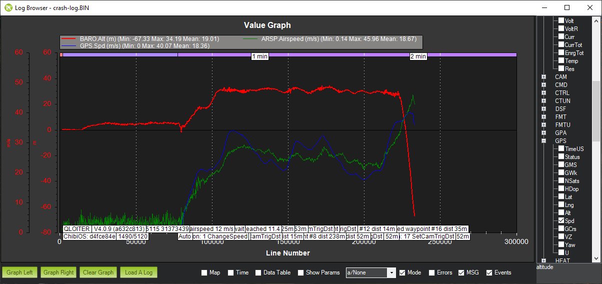
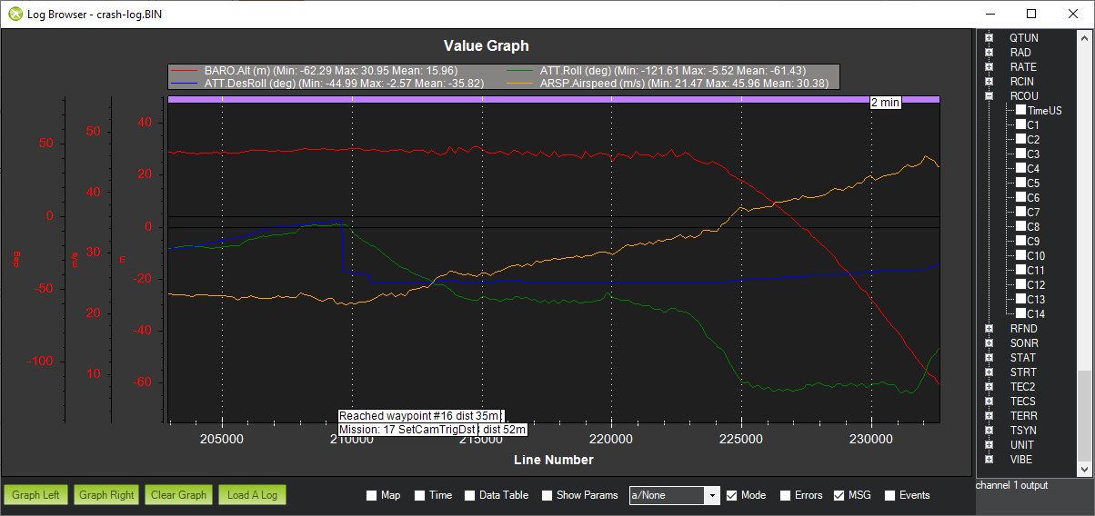
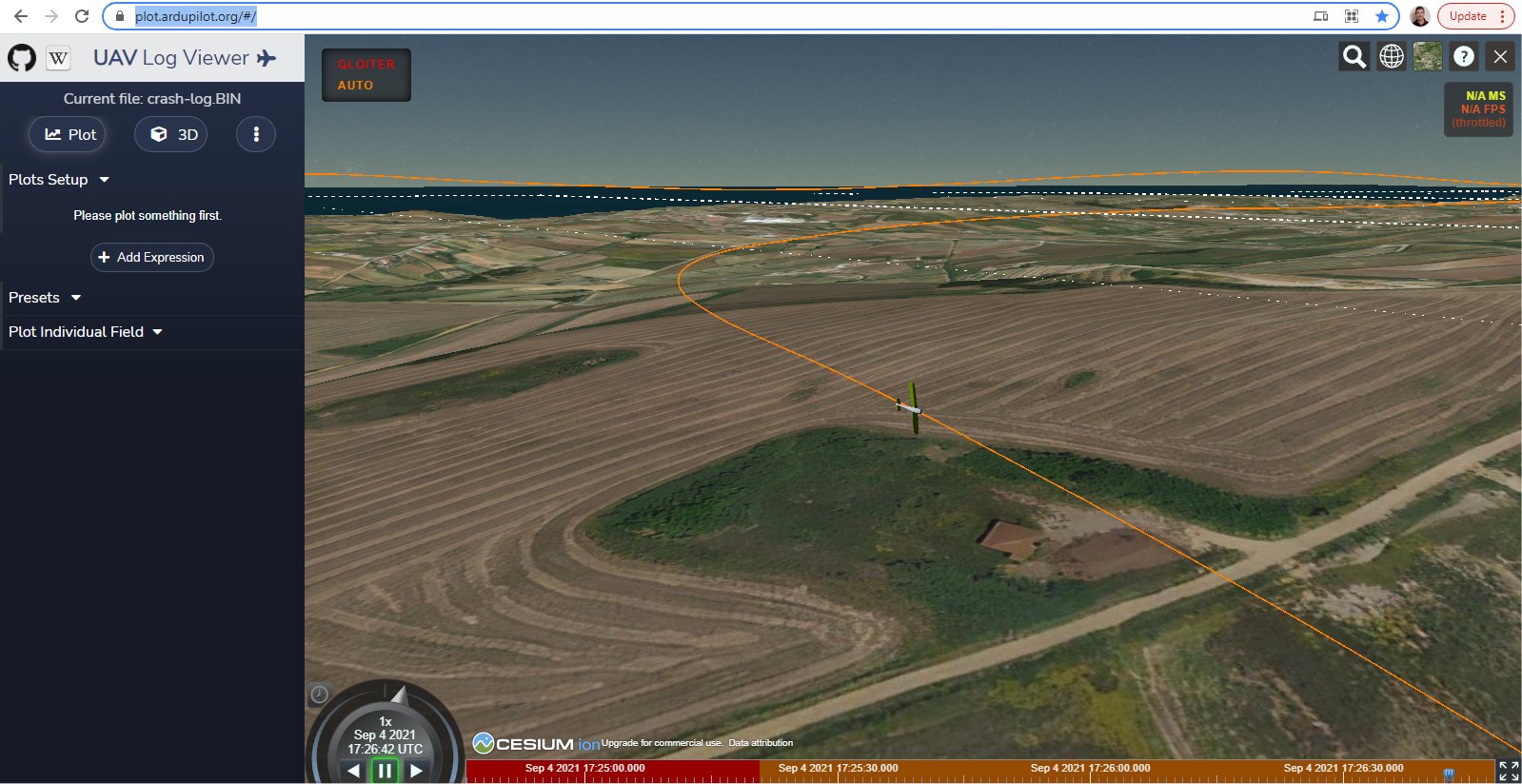
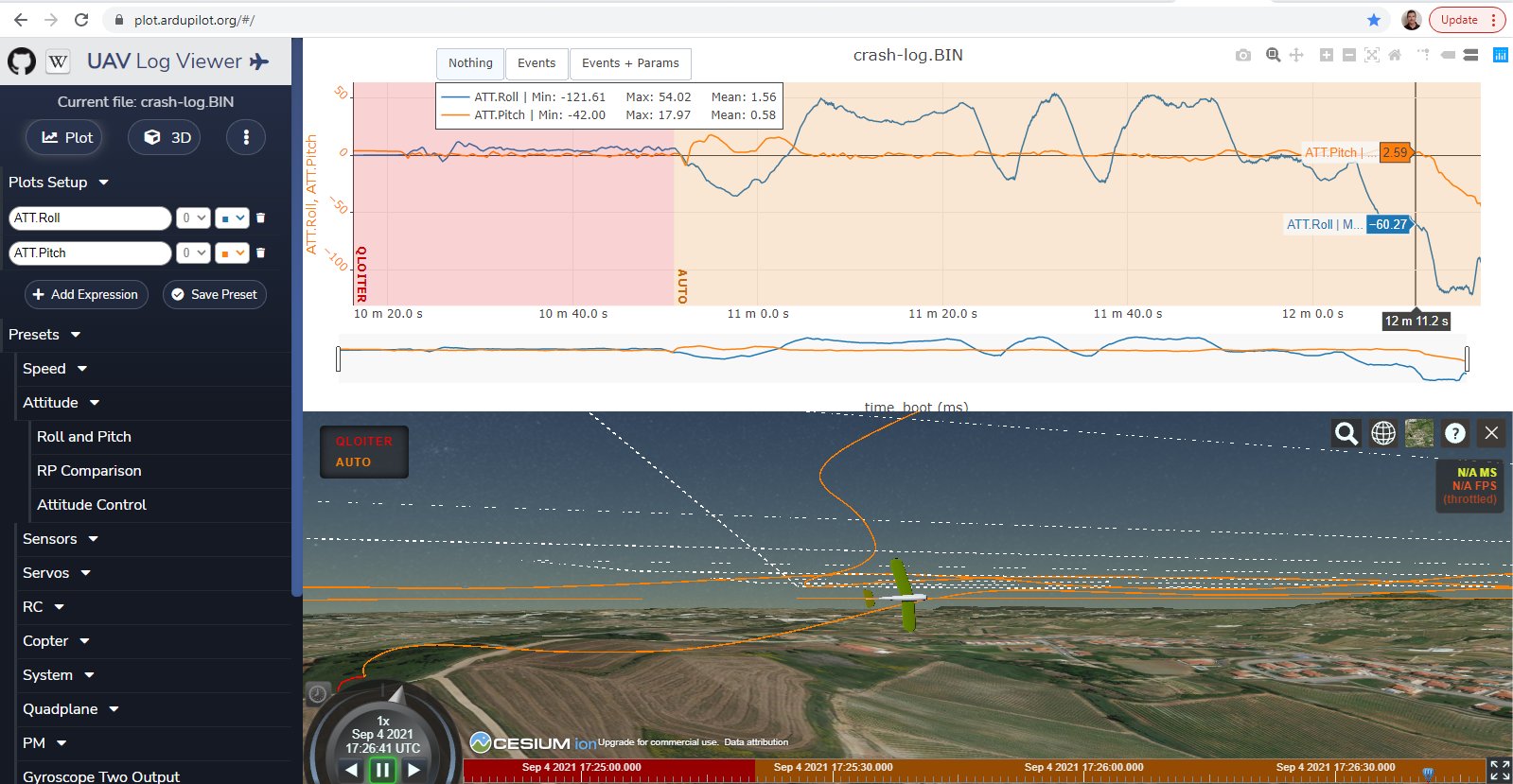
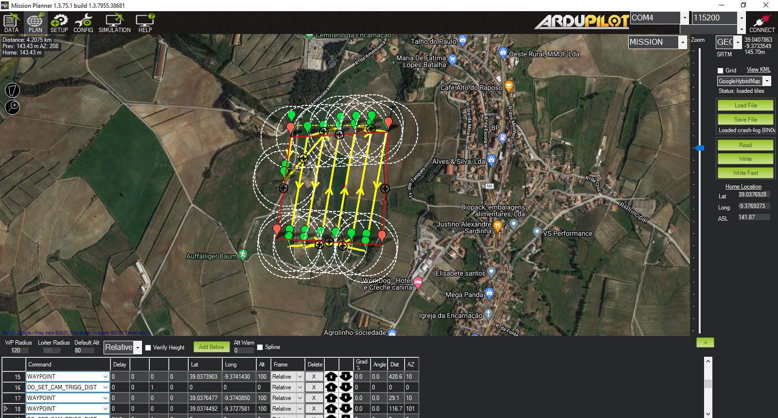
Thanks for posting your .bin file. I have looked at the log and I am still perplexed as to what happened. The plane speed and altitude were fine. The battery seems fine. It seemed that after reaching waypoint 16, the plane stopped being controlled by the flight controller. You can see the sudden drop in the blue ATT.DesRoll output in the second image. The issue seems similar to other recent reports when in AUTO mode.
Hopefully, someone else can interpret the logs for a better idea on the cause of the crash.
1 Like
Hi Ricardo,
Such a crash hurts, hopefully the damage is not serious. In my opinion, a (tip-)stall has terminated the flight. Responsible for this is an incorrect parameterization of the speed controler and at least suboptimal roll control.
After the transition the plane flies straight ahead for a few seconds at 19:26:08. There you can read that at approx. 45% throtlle (TRIM_THROTTLE,45) airspeed is 24 m/s, but not 12 m/s, as parameterized with TRIM_ARSPD_CM,1200.
The autothrottle control thus runs completely outside a reasonable control range. This is aggravated by the fact that throttle is increased in turns in order not to stall in steeper turns. Another aggravating factor is that the waypoints are much too close to be flown reasonably at this speed.
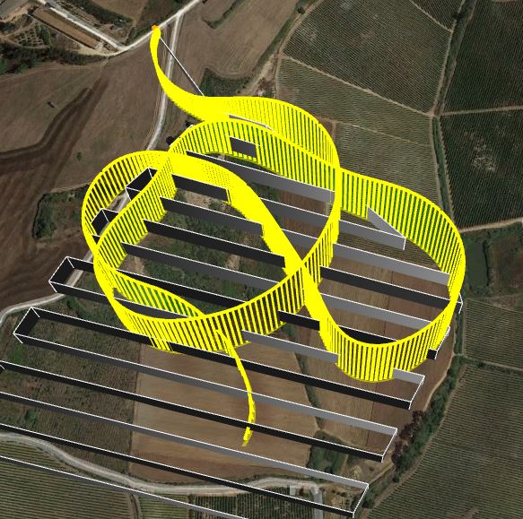
The Fighter is therefore almost continuously flying with 45° target bank curves. In the last left turn before the crash, he’s flying with almost 60° bank ( a maximum of 45° allowed).
With better roll tuning, he should actually have returned to 45°, which he did not do. Due to the high bank angle, the flight controller increases throttle and speed increases.
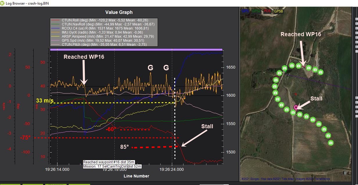
At a roll angle of 60°, the resulting force is already 2g. This means that 10 kg of force becomes 20 kg.
In addition, there are two gusts (marked with G), between which the roll angle increases further to almost 75°.
At 75 degrees bank the resulting force is 4g (as if the fighter would weigh 40 kg).
I suspect that due to the deflection of the wings already here one or both ailerons got blocked, which is easily the case in foamies.
This meant that the left-turn could no longer be deflected (blue = aileron servo output).
At 85° bank angle, even the 33 m/s airspeed is no longer sufficient to prevent a stall. It also fits that pitch breaks in exactly at 85° roll.
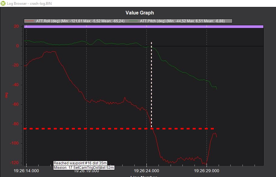
Regards Rolf
2 Likes
I’m speachless on your flight analysis!
In fact autotune was not performed in plane mode and the waypoints were way too close and seems to be flying fast but I ignored this as 10m/s stall speed seemed correct for the speed the plane was flying.
Let me know your PayPal so I can buy you a beer and for Greg also
1 Like
Alguna idea de lo que le pudo haber pasado a mi avion. No note ninguna falla de energia. Ni de servos. Solo vi que los motores se aceleraron mucho en el giro.
Ricardo,
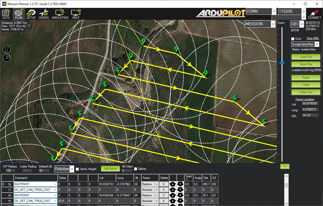
I used to fly mapping missions years ago with the BEV FireFLY6 VTOL. They had several good videos on planning a proper mapping mission and the plane would skip rows to make it easier to turn within the limits of its capabilities. These mission tools are built into Mission Planner (and I assume QGC) but you need to know how to use them. I have forgotten this knowledge over the years.
MFE has several mapping creation videos. Although they have Chinese audio, you can watch them and copy what is done on your Mission Planner.
Ground Station Operation Guide 1 - Introduction to the Main Functions of the Ground Station (v1.6)
Ground Station Operation Guide 2 - Mapping Route Planning and Generation (v1.6)
Ground Station Operation Guide 3 - Route Takeoff and Landing Waypoint Addition (v1.6)
Ground Station Operation Guide 4 - Route Elevation Data Check, Simulated Flight Check (v1.6)
Good luck!
3 Likes
Ricardo,
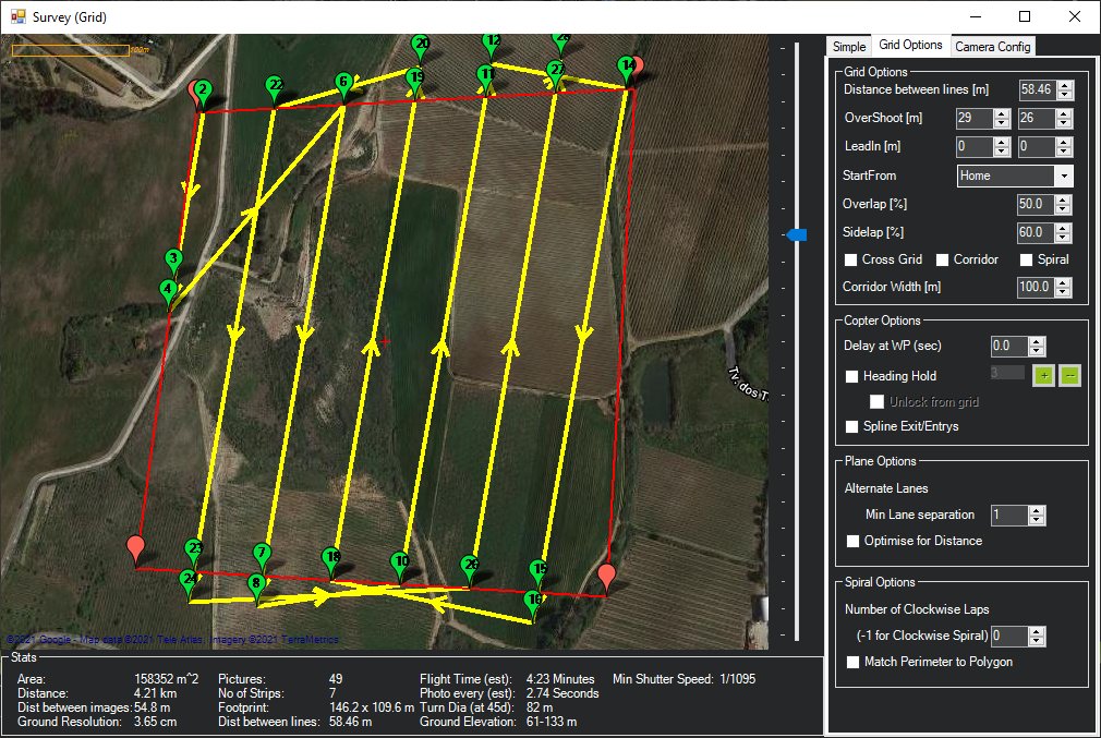
I decided to refresh my old memory on how to create the proper mapping plan. Most of it came back quickly. You’ll need to look at the MFE videos linked above to determine the limitations of the Fighter VTOL model. There are many Grid and Camera options to help keep the plane mapping properly within limitations.
From Mission Planner:
- Draw Polygon
- Select Auto WP then Survey Grid
- Check “Advanced Options”
- Go to “Grid Options” tab
- Choose Minimum Lane Separation, Distance between lines, Overshoot, etc.
2 Likes
Hi @Christian_H
I hope you are healthy, I am impressed with your built. May I ask about how you install the Multispectral Camera? Is that MicaSense Red Edge?? I also plan to install this expensive camera for my MFE Fighter. Could you share how did you make opening on the Fighter fuselage.?? Any drawing about size of this opening (hole)? Do you setup automatic triggering using the autopilot? Do you also install Sony Mapping camera at the same time…? Thank you
1 Like
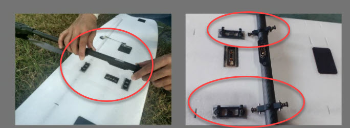
Dears
Does someone know where can I buy a "quick release tube clamp "?, It is the piece used to fix the “quad arm” in the wings. I add some images to show it. Maybe someone knows…thank
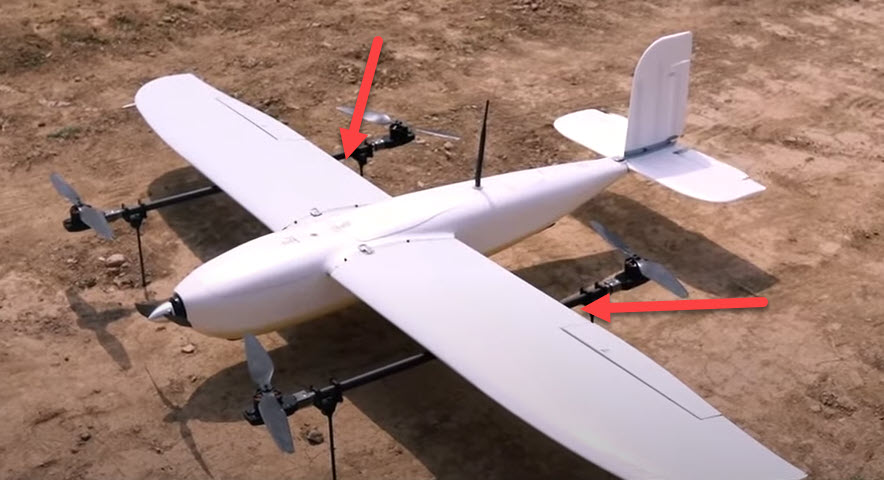
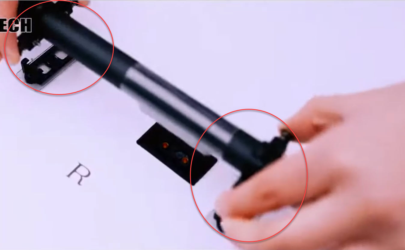
Video here> 2021 09 27 1 43 07 - YouTube
Fighter Setup.pdf (803.5 KB)
Hello,
New to the VTOL (and Ardu-- flying) world, but after years of RC flying, keen to try something new… the fighter seems to fit my scope.
Where planning to purchase the MFE fighter through 3DXR in UK, but the recommendations confuse me a little. I have tried to make a wire diagram (see attached PDF), but I think I get something wrong as I can not quite see how I power the servos - nor whats the point with the Power Module… Hope someone can shed some light for me…