Mucha prolijidad. Yo voy a montar una cámara pero por el momento sin cardan. La camara que voy a colocar es una Canon 110hs. Solo para fotografía.
Here is a small .png file I made of the Fighter 4+1 VTOL for the FrSky Horus/Taranis users. The short name of “Fight2” is needed for the filename requirements. The image size is 248x114 pixels.
Hola estoy tratando de conectar el disparo de una cámara al cuav v5 nano y tengo que usar una entrada digital para la confirmación del disparo de la camara. En pix usaba los aux 1 a 6 denominados pin 50 a 55. Saben si está placa tiene entrada digital y cuáles son sus números de pin. Gracias
Using the documentation for the CUAV V5 Nano below, I do not see any digital outputs for a camera trigger. Let’s ask Henry @hwurzburg about this since he knows most all the interfaces.
Usando la documentación para el CUAV V5 Nano a continuación, no veo ninguna salida digital para un disparador de cámara. Preguntémosle a Henry @hwurzburg sobre esto, ya que conoce casi todas las interfaces.
edit: the NANO has 8 PWM outputs and 3 “capture” outputs…all can be used as GPIOS…but to any of the first 8 you would ahve to changed the BRD_PWM_COUNT to below 8 to start using some of the higher numbered outputs…the CAPTURE pins A1-3 are always GPIOs…
the GPIO pin numbering starts at 50 for PWM1 and runs up to 60 for A3 capture input…I suggest using A1,2, or 3 (58/59/or 60) for the input
1 Like
Ok. Muchas gracias
Saludos
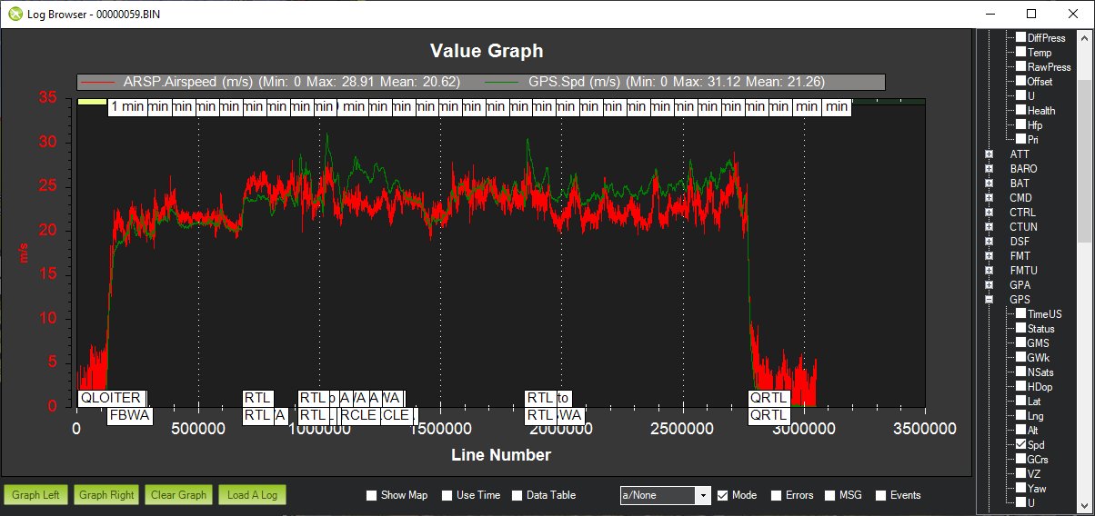
Hola. Ya estoy haciendo vuelos y el avion se comporta muy bien. El tema es que tengo algun problema con el sensor de velocidad de aire. Lo calibre con se explica pero cuando lo active para el control de velocidad el avion se volvio loco variaba mucho la velocidad. Lo intente configurar tube order en 0 o en 2 y lo mismo. Observo en el log que varia mucho la velocidad del aire y no me parece normal. Adjunto el log para que vean el problema a ver si pueden saber lo que estaria pasando.
https://drive.google.com/file/d/1XbJZnIPsNRQKDB94GGMbhWfEJYGt1hnN/view?usp=sharing
Hi,
I am glad to hear that you Fighter 4+1 is both hovering and flying well. At first glance, it appears that your Air Speed sensor is working well. It appears to be calibrated and follows the GPS air speed unless there is some wind.
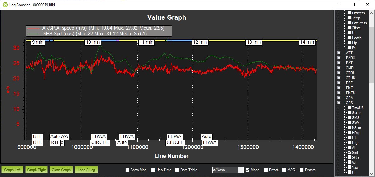
However, I do not understand all the mode changes in the lower image. I would not use RTL or AUTO during the flight and simply go from FBWA to LOITER and leave it there for a few minutes. Hopefully, this is how you calibrated the sensor as well. Then post a log with a several minute run in LOITER mode. Cheers!
Hola,
Me alegra saber que tu Fighter 4 + 1 está flotando y volando bien. A primera vista, parece que su sensor de velocidad del aire funciona bien. Parece estar calibrado y sigue la velocidad del aire del GPS a menos que haya algo de viento.
Sin embargo, no entiendo todos los cambios de modo en la imagen inferior. No usaría RTL o AUTO durante el vuelo y simplemente iría de FBWA a LOITER y lo dejaría allí por unos minutos. Con suerte, así es como calibraste el sensor también. Luego publique un registro con una ejecución de varios minutos en modo LOITER. ¡Salud!
Hi all,
I have 2 Clouds planes, and I’m getting around 55 min flight time with 6S 10.000 mah.
I’m interested on this fighter vtol. Do you have an estimated flight time of the Fighter vtol with a 6S configuration? I´m not interested in a high payload, only a 1" sensor camera and ppk gps.
Thanks
Hi Doppler,
There are many variables that affect flight time. Comparing a VTOL to a non-VTOL is like comparing apples to oranges. The Fighter 4+1 VTOL has a longest flight range specification of 150km with a 600g payload. Presumably, this is the 12s 16AH setup. My setup is 6s 21AH so we will see this summer.
Cheers!
1 Like
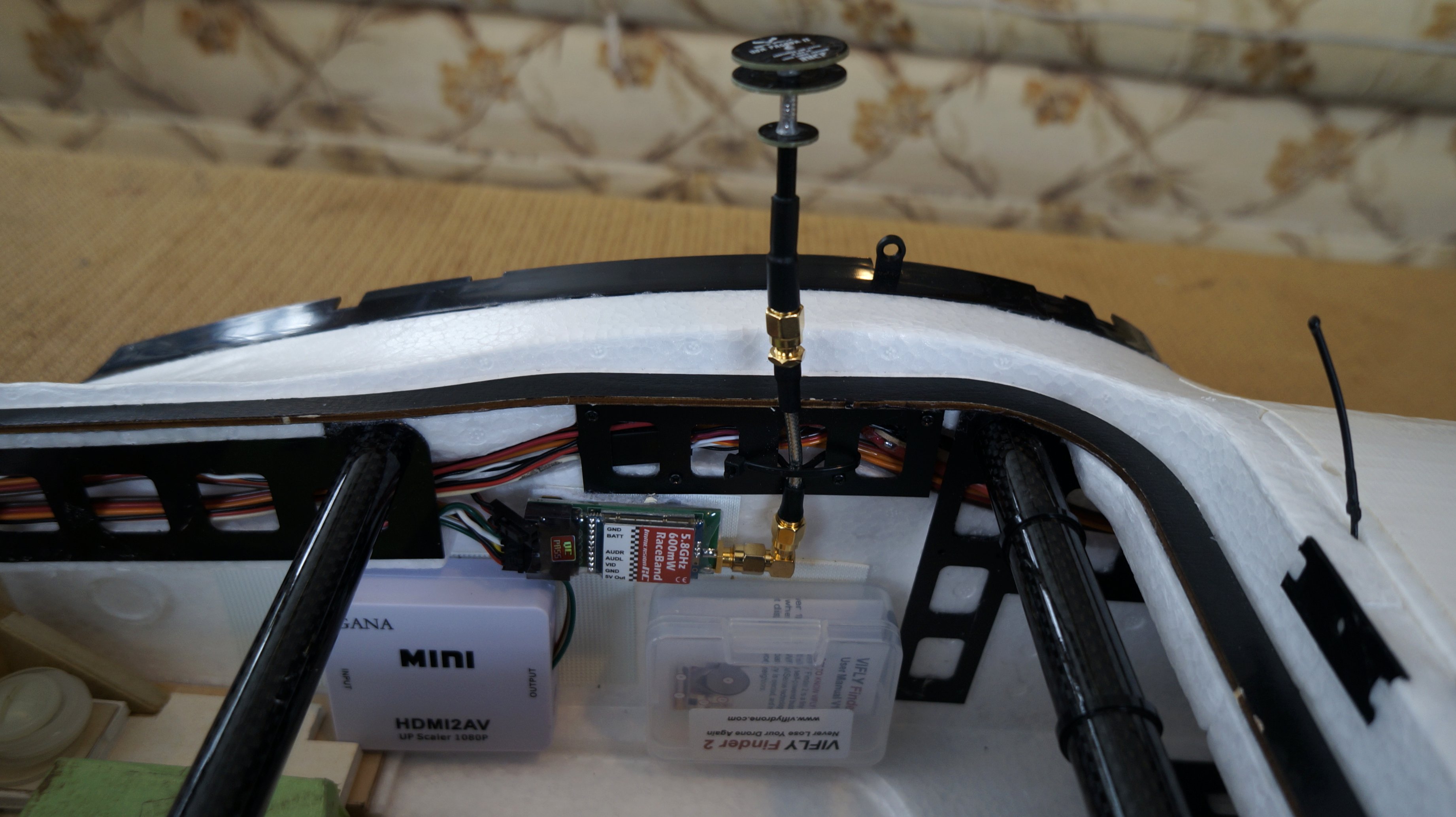
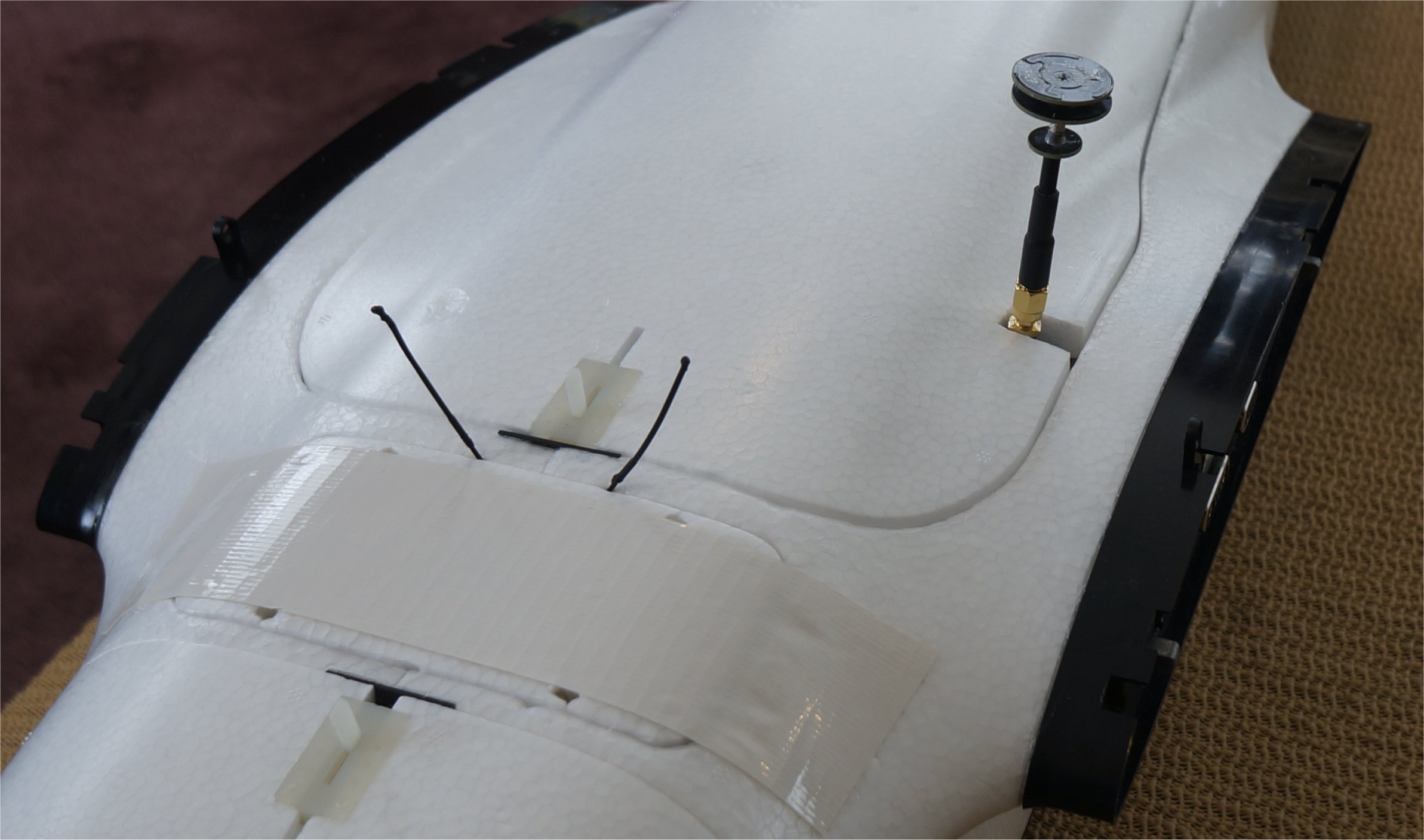
I remounted my 5.8GHz Pagoda 2 antenna so that it faces up. It can also be unscrewed and stored inside the fuselage for transport. The 5cm Semi-Rigid Extension helps to raise the antenna and lock it in place with a cable tie.
1 Like
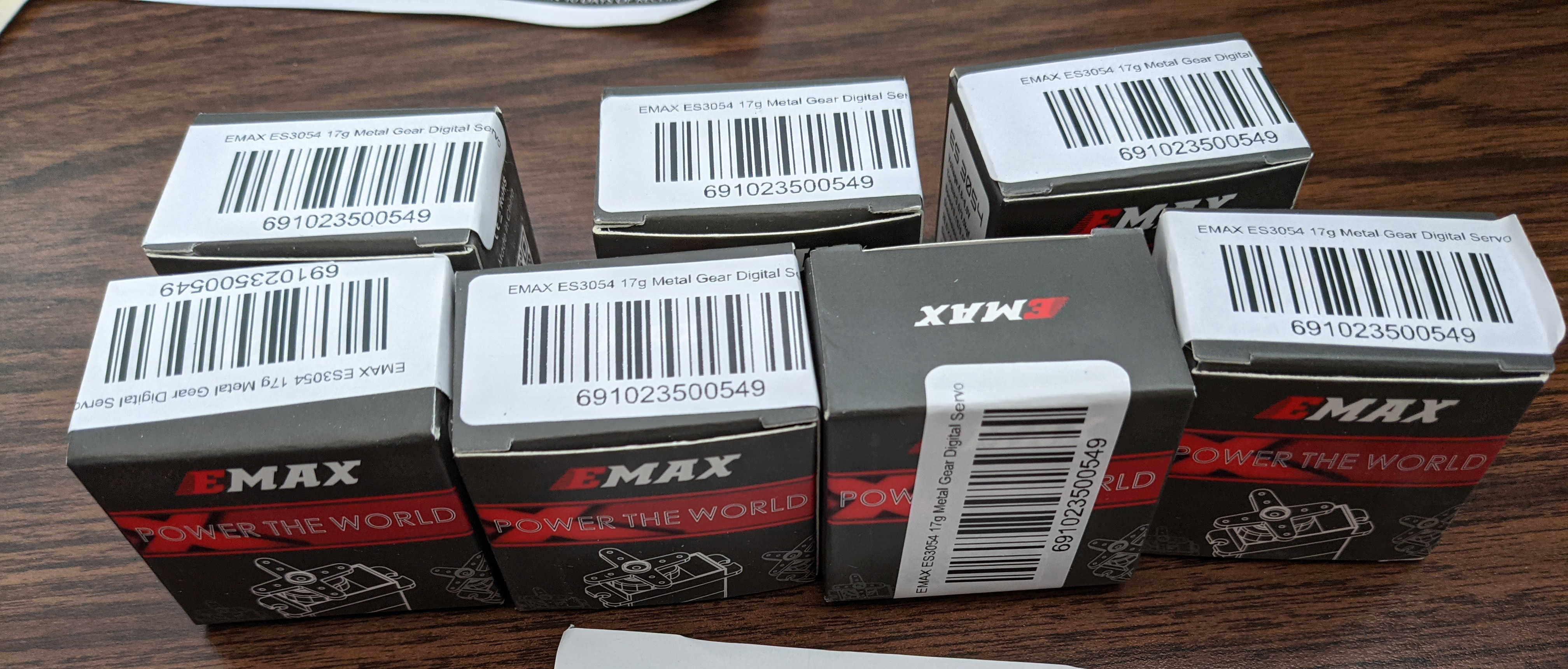
Parts are finally showing up!
I’ll get to start laying out to make sure everything fits and then building soon.
-Christian
2 Likes
Looking Good! Interested how those motor/esc combos work for you.
1 Like
Hello,
Please give me a quote to accomplish any parts of the below project outline.
Thank you,
Tim Chapman
I am willing to separate this RFQ into pieces for different people to work on who have expertise in each area required.
If someone knows how to do all this without the ATMEGA2560 PCB, I am all ears.
My setup is as follows:
Taranis X9D transmitter with RFD TXMOD transmitting radio control and telementry.
- I want to be able to control transmit power level as outlined below using a channel on the transmitter.
Quad copter has:
- TBS UNIFY PRO32 HV video transmitter
- RFD900x telemetry transceiver connected to Pixhawk 2.4.8 via sbus.
- Runcam Split 3 Micro with DVR.
My objectives are to be able to:
- change the TBS UNIFY PRO32 HV video transmitter power level.
- Change RFD900x transceiver power level
- start and stop Runcam Split 3 Micro recording video.
- change the TX MOD power level.
I want these changes to be made using 4 separate radio channels with PWM outputs from the Pixhawk:
7 SB 3 position. RXD900x power level. 0dbm, 15dbm, 30dbm.
9 SG 3 position RC Transmitter (TX MOD) power level. 0dbm, 15dbm, 30dbm.
14 SE 3 position Video transmitter power level. 25mw, 400mw, 1000mw.
15 SF 2 position Video record or not.
Do I need to manually change the data rates of the TX MOD/RDF900x or if they will automatically set based on power levels?
If I have to control them, use channels 12 and 16 for this. These are SC and SD. Both are 3 position swtiches.
My plan is to have a small 3.3V atmega2560 pcb with level shifters if needed in the quad copter.
It will receive PWM input from the Pixhawk channels specified.
It will output the appropriate serial data to each device to control it accordingly.
If the device returns any data confirming its status, the atmega2560 will receive and verify the status for display on the DIY OSD below.
On startup, make the arduino put each device in the correct mode at the lowest power level.
Taranis will start up with switches in their rearmost position to avoid switch warning. This position of each switch will be lowest power on transmitters and video recording off.
The runcam and dvr runs on 5V. As far as I know the serial connection to the DVR is 3.3V.
I know the TBS UNIFY PRO32 HV video transmitter is 3.3v.
The RXD900x is 5V. Serial data interface is 3.3v.
The reason for doing this with the channels instead of moving through menus using the joysticks is that I won’t have to look down at the transmitter to make changes. I can just flip channel switches. I am setting up a MFE Fighter VTOL for search and rescue and I just don’t have enough time to figure all this stuff out.
Install DIY OSD (https://www.ebay.com/itm/283984411019) and video switcher (SmartFPV RC Camera Control v2.0 - https://smartfpv.com/store/video-switches/2-rc-camera-control-v2.html - I own 4 of these. They are no longer made.).
Connect DIY OSD to atmega2560.
Have atmega2560 output text to show me status of each device including LEDs, temperatures, power levels.
Have Atmega 2560 measure temperature of 5 ESCs and video transmitter and report this on DIY OSD as well. This will later be used in a VTOL aircraft which will have 5 ESCs. For now it will be 4 on my quad copter.
I am expecting that the number of items that will require temperature monitoring will increase to a maximum of 16 since there are 16 analog input pins on the ATMEGA2560.
Video switch will be controlled by RC Channel 11. This is a momentary switch. In its normal position, it will show me the MinimOSD output. When switched, it will show me the DIY OSD output.
It might make sense to use channel 8 to control the Minim OSD screens and the video switcher.
Make the ATMEGA2560 log the temperatures and power levels. It will need a time reference to match the logging on the Pixhawk. This should be when the Pixhawk is armed. Is there a way to make the pixhawk output a unique sequence on channel 11 for example when the Pixhawk is armed to tell the ATMEGA to start logging and set its time reference to zero?
Another way to handle the time is to connect the GPS to the ATMEGA2560 as well as the Pixhawk. The ATMEGA2560 can get the time from the GPS. Does the Pixhawk use the GPS as a time reference for logging as well?
The ATMEGA2560 would only need to read the GPS and get the time when it was logging something. That would be when one of the data values or switch positions changed.
My intent is to use this Arduino Mega 2560 pcb: https://www.ebay.com/itm/Mini-Meduino-Mega-2560-R3-Board-Pro-Mini-ATMEGA16U2-Female-header-for-Arduino/382570244931
I will design and have an interface PCB made which will have all the needed connections.
NOTE: The ATMEGA2560 is to be programmed entirely in BASCOM AVR with code that is commented well so that I can maintain it in the future.
I may omit this requirement if necessary to find someone who can do this project in a .ino file.
Lastly, is there any easy way to connect a signal from the ATMEGA2560 pcb to the Pixhawk that will inform me if there is an error on the ATMEGA2560 data?
Taranis X9D channels, switches and their uses:
1 Thr
2 Ail
3 Ele
4 Rud
5 S2 MODE SWITCH - 5 position.
6 S1 CAMERA PAN
7 SB 3 position. RXD900x power level. 0dbm, 15dbm, 30dbm.
8 SA MinimOSD OSD VIDEO SCREENS.
9 SG 3 position RC Transmitter (TX MOD) power level. 0dbm, 15dbm, 30dbm.
10 LS left slider. CAMERA TILT.
11 SH momentary. Control Video switch (SmartFPV RC Camera Control v2.0).
12 SC 3 position. Use for TX MOD data speed if needed.
13 RS right slider. LEDs.
14 SE 3 position Video transmitter power level. 25mw, 400mw, 1000mw.
15 SF 2 position Video record or not.
16 SD 3 position. Use for RXD900x data speed if needed.
PCB Design:
I think shielded cable might be needed for all connections?
- noise filtering caps on each analog input and power output to each analog temperature sensor.
- locking connectors for each connection?
- inputs from PWM outputs of Pixhawk.
- locking connectors to TBS UNIFY PRO32 HV, RFD900x, Runcam Split 3 Micro.
- GPS input.
- output to DIY OSD. Locking connector.
MFE News
MFE has released 2D/3D drawings of their planes so that their customers can more easily produce DIY or 3D printed parts. They are stored on GitHub here.
In order to facilitate the global drone enthusiasts to better assemble, debug, and use the aircraft, we open source some mechanical drawings for DIY use.
The delay in realizing MFE products at Banggood is due to the impact of the epidemic. It is hoped to be resolved in 2021.
1 Like
I guess they are still working on releasing files. It’s pretty limited so hopefully they will provide more in the future. Perhaps after the Chinese new year.
There are param files and manuals though.
Tim,
Have you posted this RFQ to the general ardupilot topic forum? You might have better luck finding someone that has the bandwidth to take this on.
Cheers,
Christian
Hi Christian_H,
Thanks for the suggestion. I just posted it to the Jobs section:
I hope that helps since I have not gotten any responses from the other places I have posted it.
1 Like
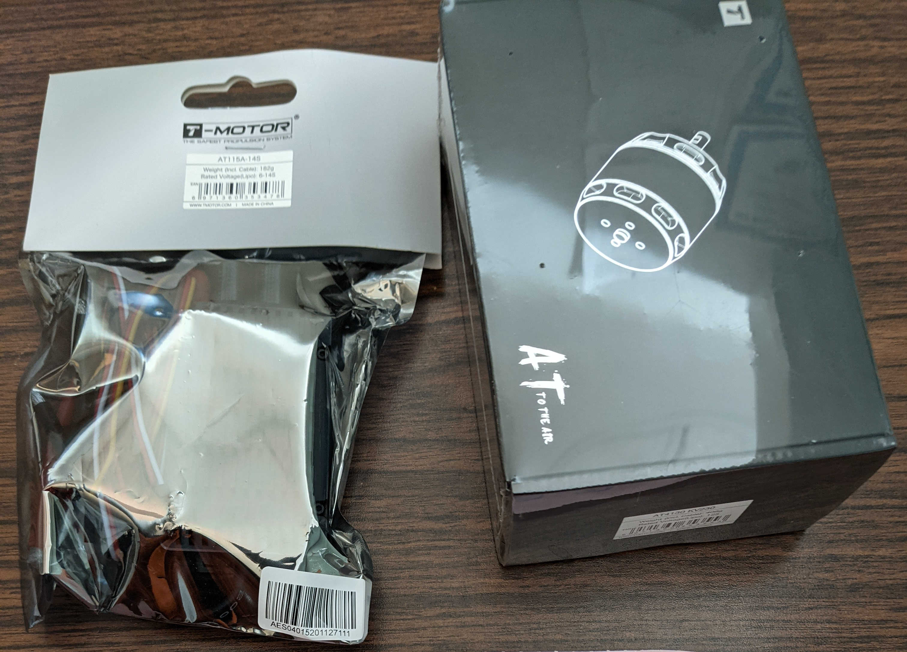
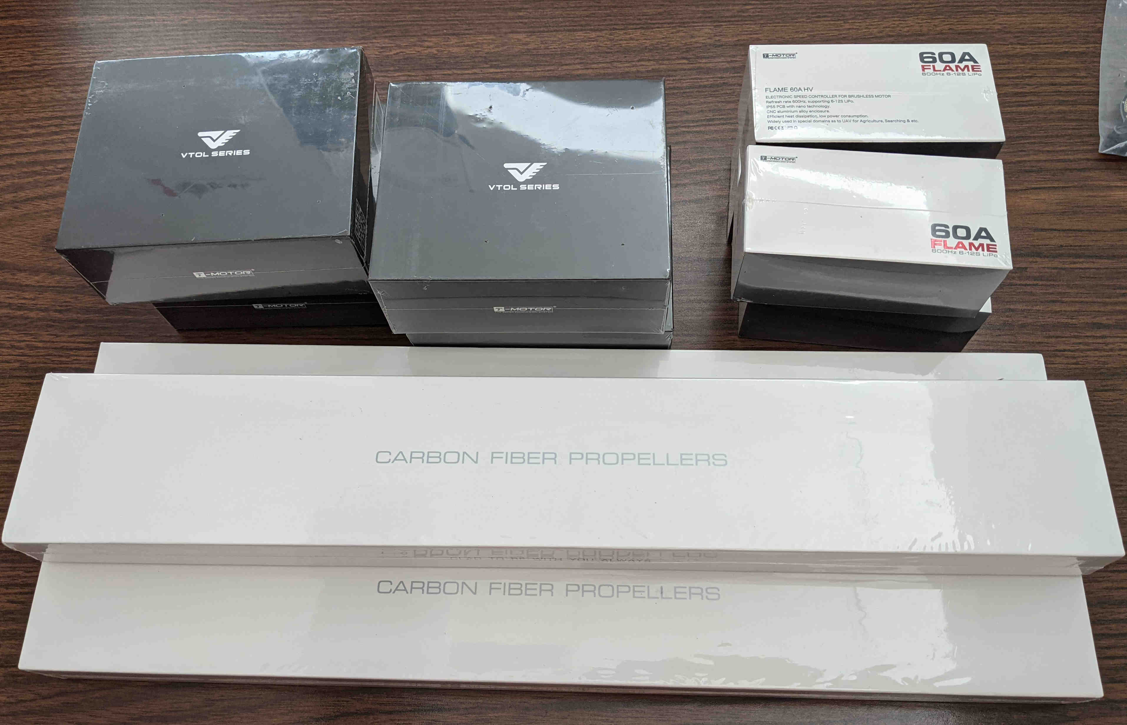
So I ran into a small obstacle with the VTOL motors. Originally I had planned to use the integrated TMotor kits ( 601-X) but was convinced to go with the newer V505 KV260 VTOL specific motors by a TMotor representative. The tradeoff was a smaller 17" prop (for less drag) with a higher thrust motor vs. a lower Amp, slightly higher efficiency motor. Note: the 12S TMotor ESC’s are massive compared to 6S.
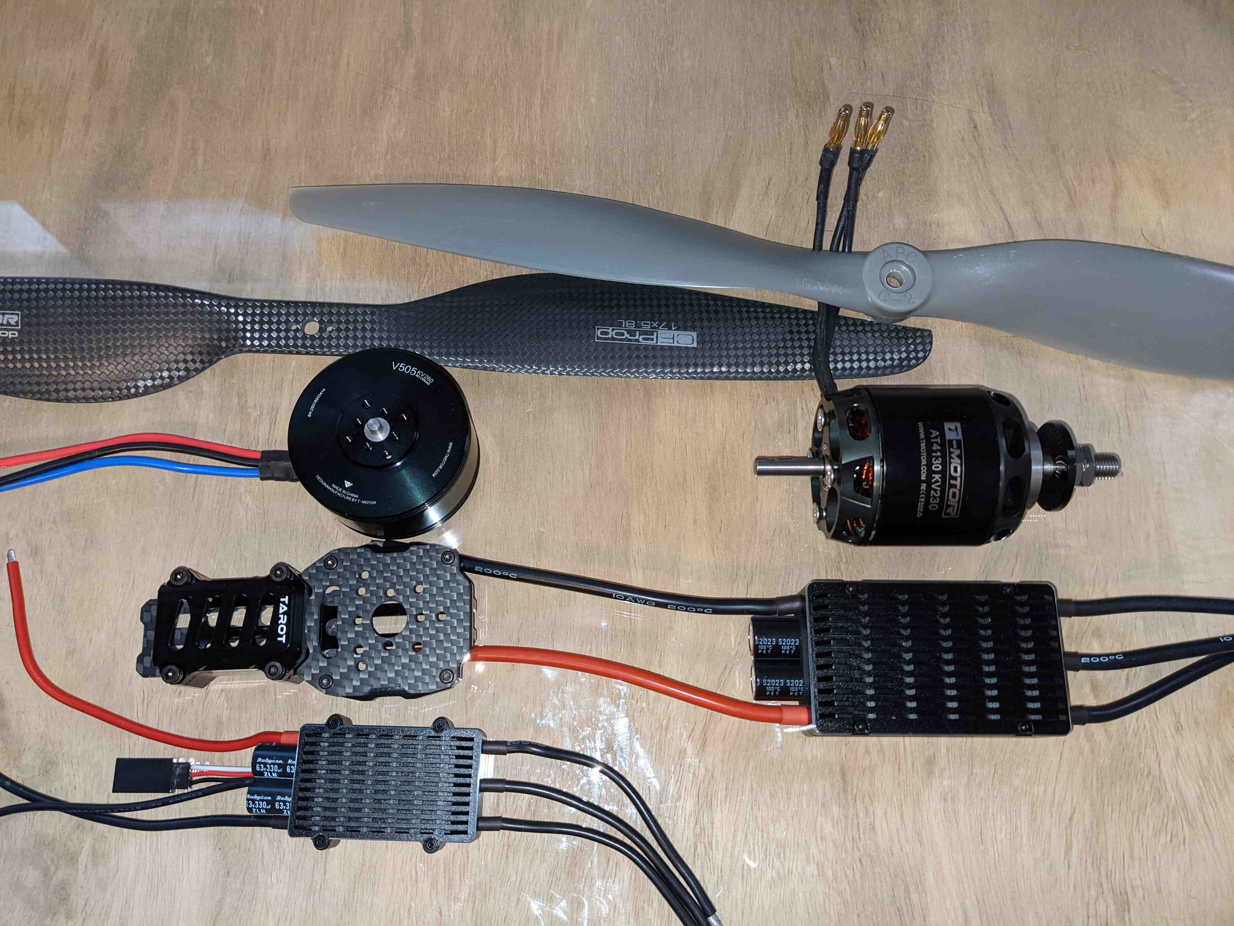
Photo 1: Propulsion components
Looking at specs online I knew that the required ESC would not fit inside the MFE motor mounts which meant I’d need a 3rd party mount. I found a Tarot motor mount that had the right bolt pattern spacing and looked well-designed.
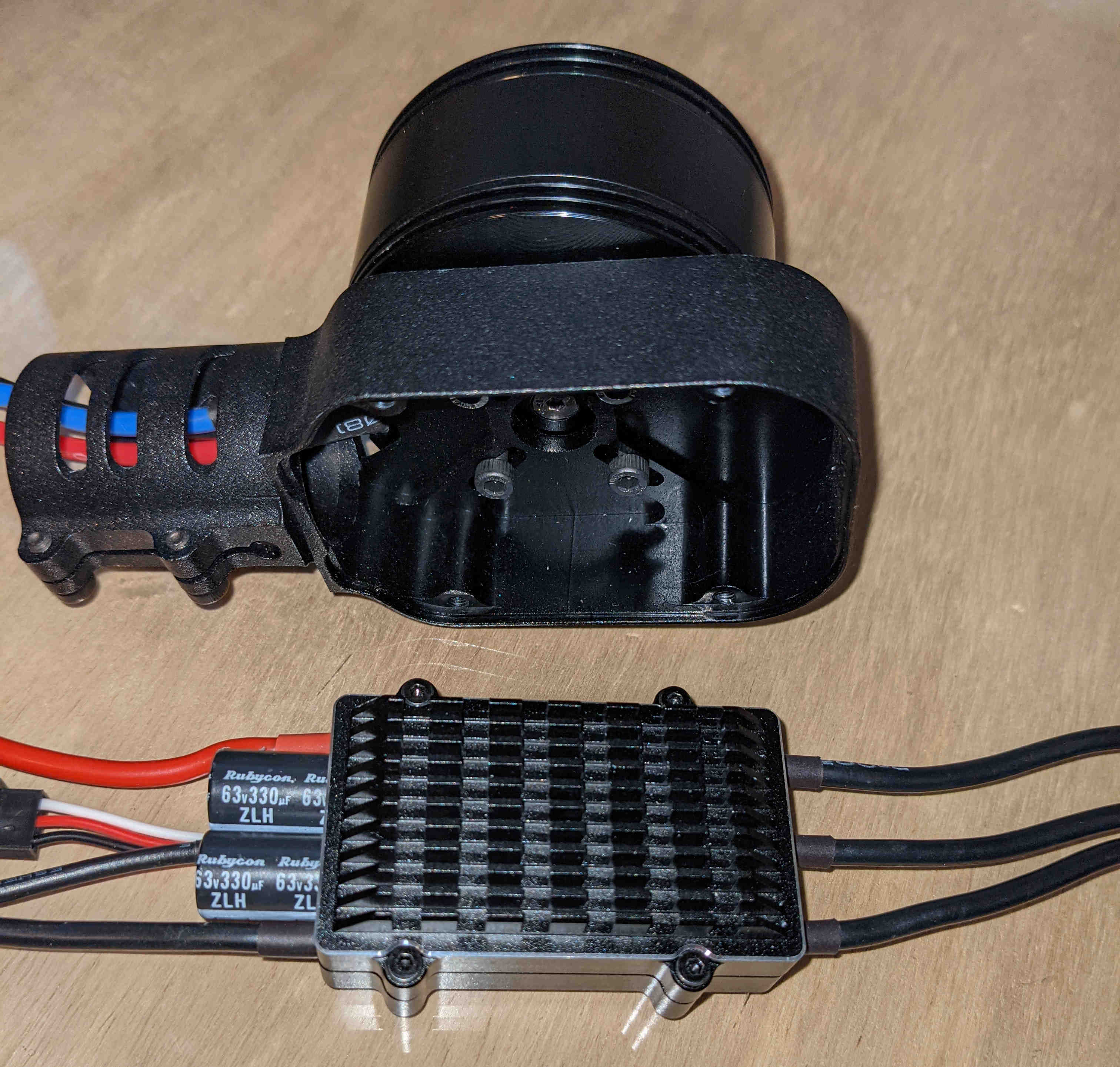
Photo 2: 12S VTOL motor ESC and MFE motor mount
Once I got to a test fit, the Taro motor mount didn’t quite have the clearance for the VTOL motor. It was a close fit but I needed another 4mm of clearance for everything to fit perfectly. My options are:
- cut/trim the aluminum back on the Tarot housing
- add spacers to the bottom of the motor for clearance
- get a piece of carbon fiber sheet and make a new mount with holes offset
**
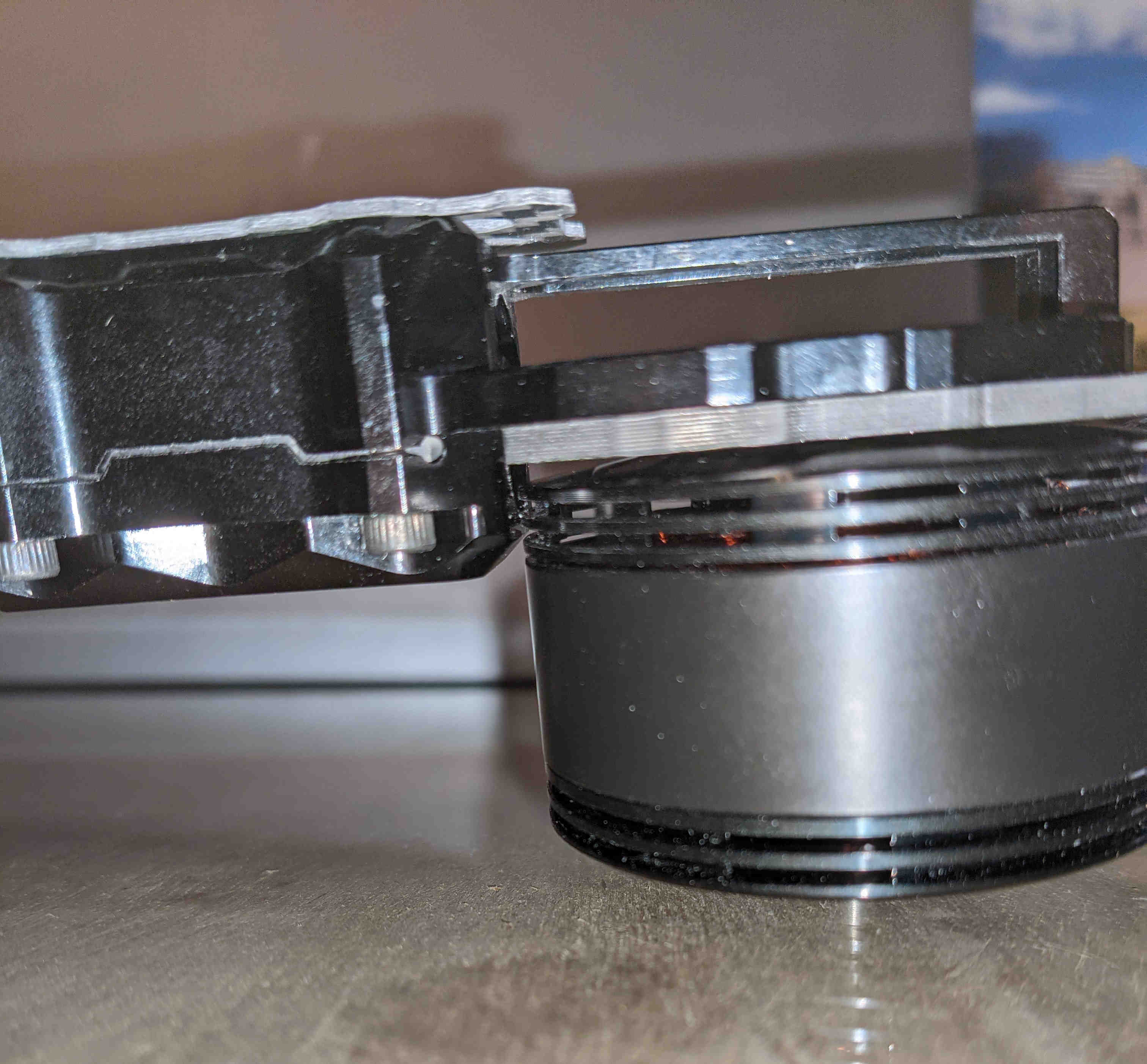
Photo 3: VTOL motor mounted to carbon fiber plate has clearance issues
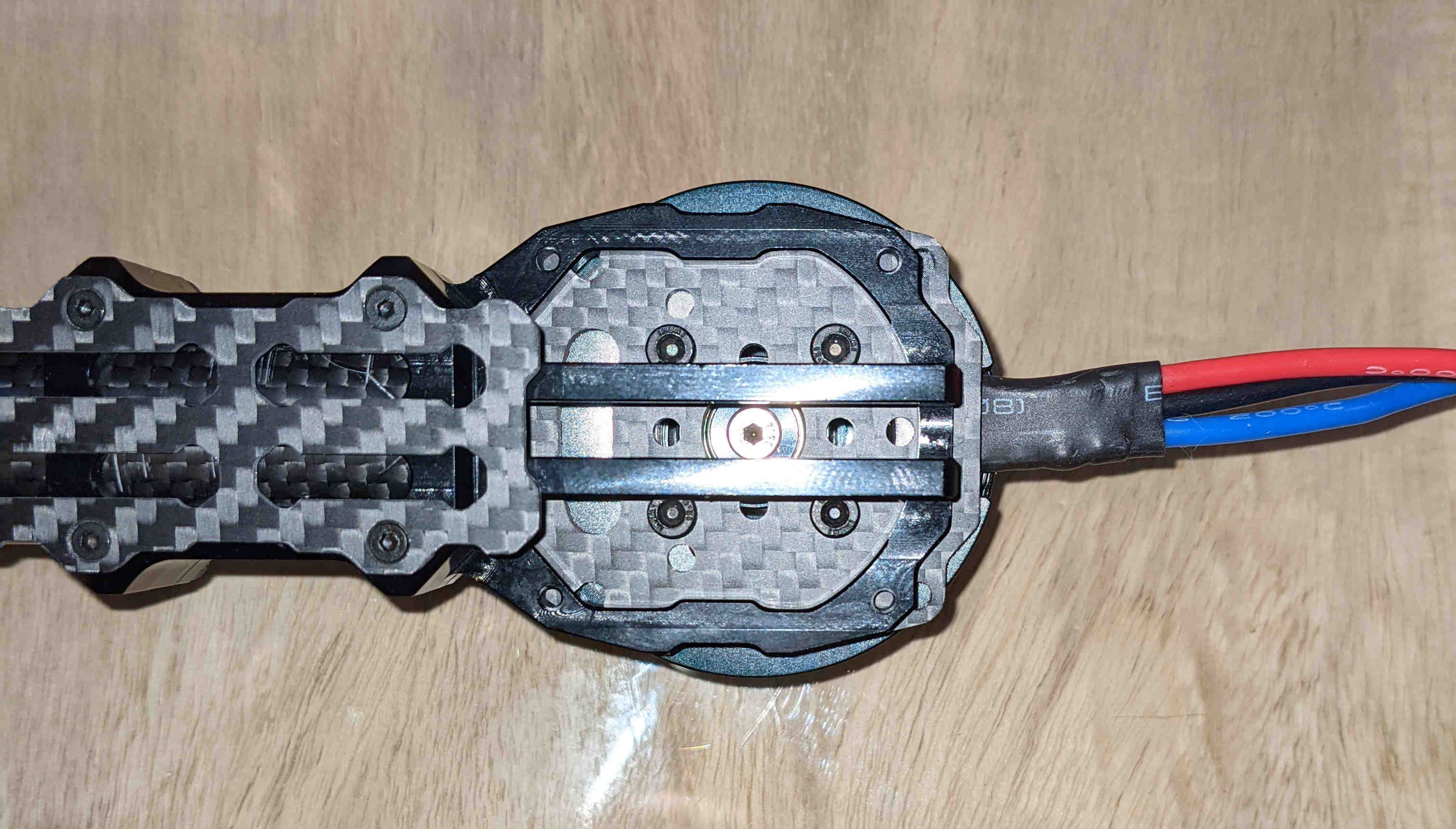
Photo 4: fit of VTOL motor mounted to carbon fiber plate is off by 4mm
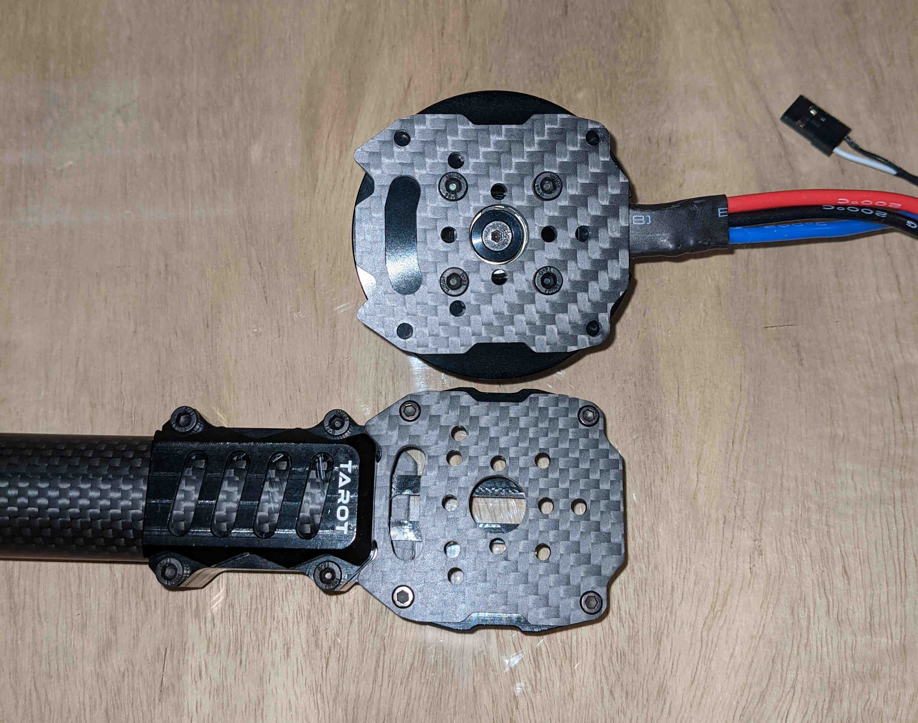
Photo 5: VTOL motor and carbon fiber mounting plate alignment
Since I will need to make a custom battery tray for the 2 battery system (VTOL and FF) and sling load suspension mounting point I’ve decided to go ahead and make new carbon fiber motor mount plates. The area on the Tarot motor mount is meant for an ESC is slightly under-sized so I’ll make a new carbon fiber bracket that will accommodate the TMotor 12S ESCs.
I couldn’t source a motor mount similar enough to MFE stock part and the alternative would be something that brings the motor in closer to the body (https://speedyfpv.com/products/25mm-3k-carbon-fiber-tube-motor-mount-with-esc-bracket-aluminum) which I feel is not ideal. The Tarot mounts will put the motors in nearly the same spot as the stock MFE parts after I make a new carbon fiber plate.
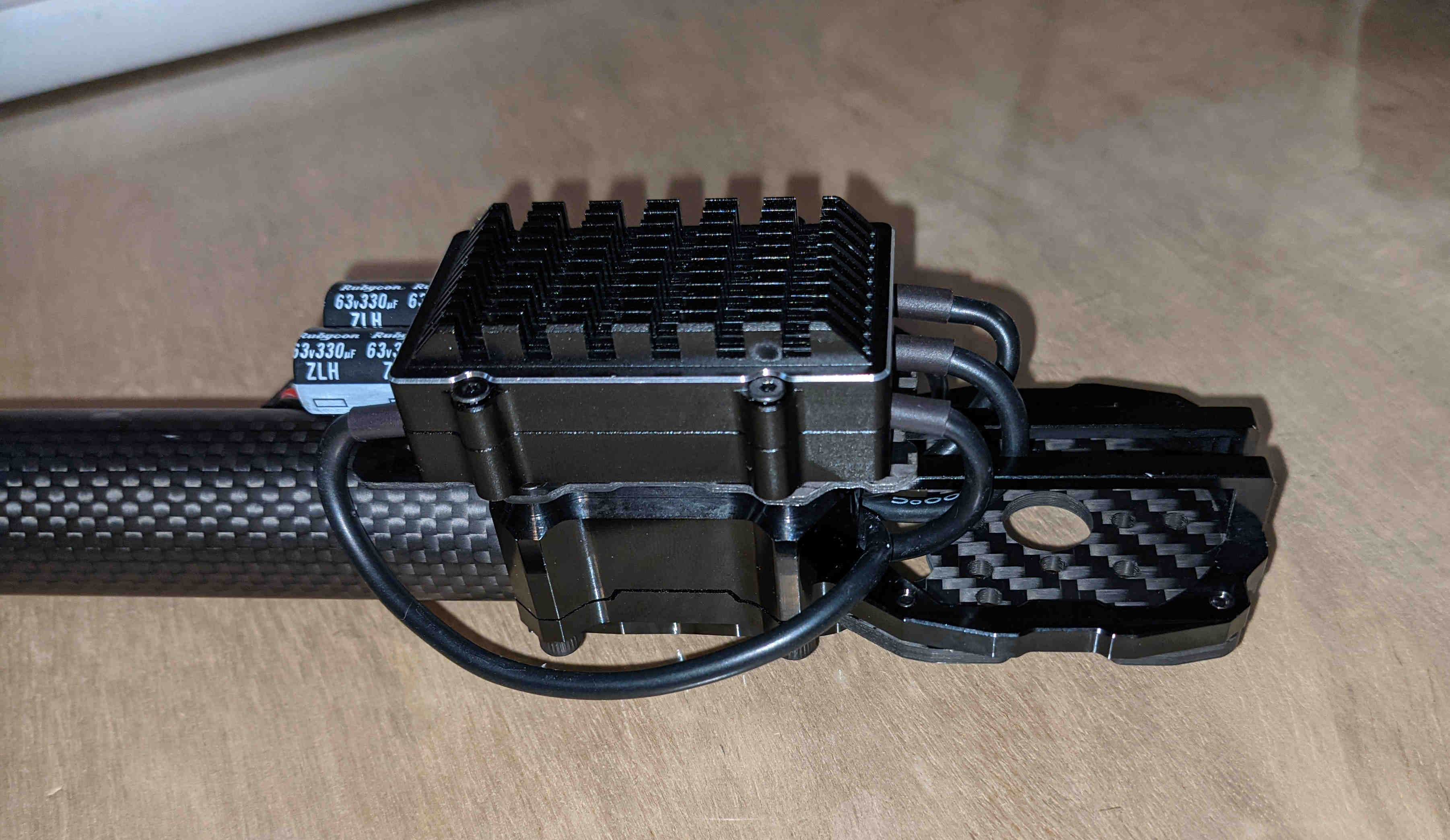
Photo 6: ESC mounting position on motor mount
Out of curiosity, I got a few 200A PDBs from Foxtech thinking I’d use them in the body and on the wings for junctions in the VTOL power system. They only weigh 9g and fit in the wings perfectly. I will likely solder the VTOL power lines directly, however, it is nice to have other options if you can afford the weight.
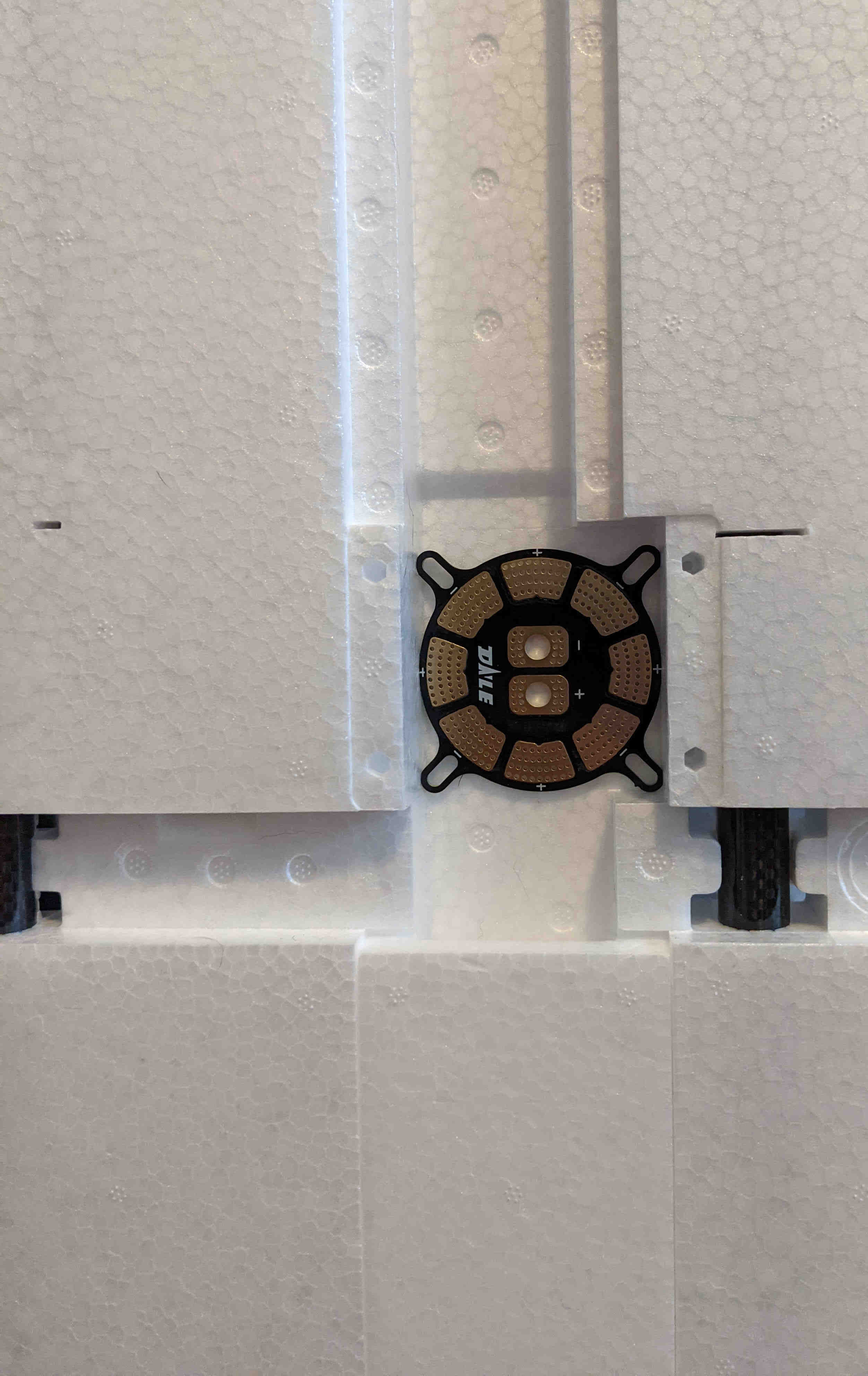
Photo 7: power distribution board
More to come later…
Cheers,
Christian
1 Like